Page 287 of 698

5-14 BRAKES
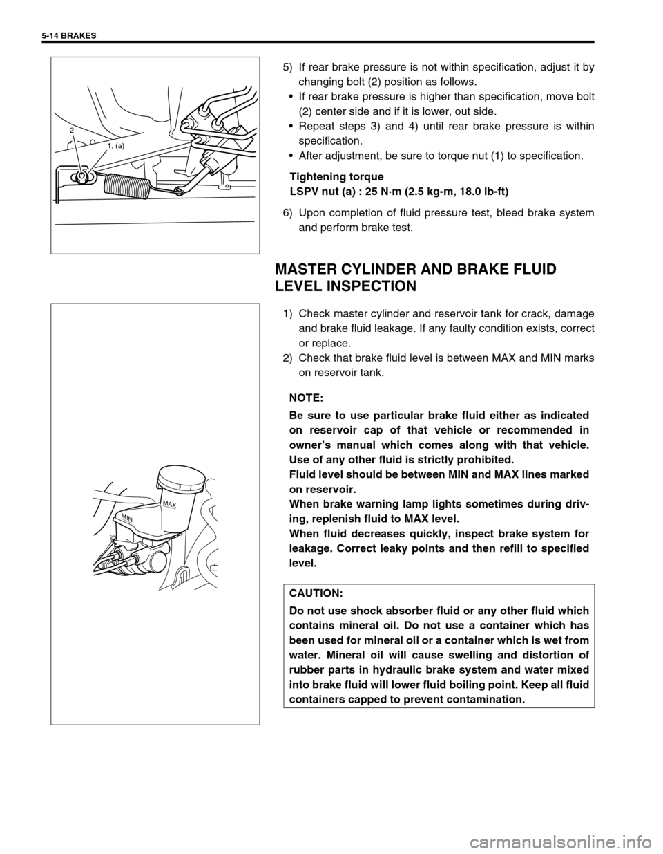
5) If rear brake pressure is not within specification, adjust it by
changing bolt (2) position as follows.
If rear brake pressure is higher than specification, move bolt
(2) center side and if it is lower, out side.
Repeat steps 3) and 4) until rear brake pressure is within
specification.
After adjustment, be sure to torque nut (1) to specification.
Tightening torque
LSPV nut (a) : 25 N·m (2.5 kg-m, 18.0 lb-ft)
6) Upon completion of fluid pressure test, bleed brake system
and perform brake test.
MASTER CYLINDER AND BRAKE FLUID
LEVEL INSPECTION
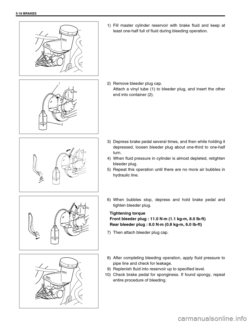
1) Check master cylinder and reservoir tank for crack, damage
and brake fluid leakage. If any faulty condition exists, correct
or replace.
2) Check that brake fluid level is between MAX and MIN marks
on reservoir tank.
2
1, (a)
NOTE:
Be sure to use particular brake fluid either as indicated
on reservoir cap of that vehicle or recommended in
owner’s manual which comes along with that vehicle.
Use of any other fluid is strictly prohibited.
Fluid level should be between MIN and MAX lines marked
on reservoir.
When brake warning lamp lights sometimes during driv-
ing, replenish fluid to MAX level.
When fluid decreases quickly, inspect brake system for
leakage. Correct leaky points and then refill to specified
level.
CAUTION:
Do not use shock absorber fluid or any other fluid which
contains mineral oil. Do not use a container which has
been used for mineral oil or a container which is wet from
water. Mineral oil will cause swelling and distortion of
rubber parts in hydraulic brake system and water mixed
into brake fluid will lower fluid boiling point. Keep all fluid
containers capped to prevent contamination.
MAX
MIN
Page 289 of 698

5-16 BRAKES
1) Fill master cylinder reservoir with brake fluid and keep at
least one-half full of fluid during bleeding operation.
2) Remove bleeder plug cap.
Attach a vinyl tube (1) to bleeder plug, and insert the other
end into container (2).
3) Depress brake pedal several times, and then while holding it
depressed, loosen bleeder plug about one-third to one-half
turn.
4) When fluid pressure in cylinder is almost depleted, retighten
bleeder plug.
5) Repeat this operation until there are no more air bubbles in
hydraulic line.
6) When bubbles stop, depress and hold brake pedal and
tighten bleeder plug.
Tightening torque
Front bleeder plug : 11.0 N·m (1.1 kg-m, 8.0 lb-ft)
Rear bleeder plug : 8.0 N·m (0.8 kg-m, 6.0 lb-ft)
7) Then attach bleeder plug cap.
8) After completing bleeding operation, apply fluid pressure to
pipe line and check for leakage.
9) Replenish fluid into reservoir up to specified level.
10) Check brake pedal for sponginess. If found spongy, repeat
entire procedure of bleeding.
MAX
MIN
MAX
MIN
Page 290 of 698
BRAKES 5-17
FRONT BRAKE
BRAKE PAD
REMOVAL
1) Loosen wheel nuts and with vehicle lifted up, remove
wheels.
2) Remove caliper pin bolts (1).
1. Brake caliper carrier 9. Bleeder plug cap
2. Boot 10. Pad spring
3. Caliper 11. Anti noise shim
4. Disc brake piston 12. Caliper pin bolt
5. Piston seal
: Apply fluid (Brake, power steering or automatic transmission fluid).13. Brake disc
6. Cylinder boot
: Apply fluid (Brake, power steering or automatic transmission fluid).14. Slide pin
: Apply lithium grease (99000-25010).
7. Brake pad Tightening torque
8. Bleeder plugDo not reuse.
9
1
7
13
2
143
1226 N·m(2.6 kg-m)
85 N·m(8.5 kg-m)
8
8.5 N·m(0.85 kg-m)
10
5 4
6
11
Page 291 of 698

5-18 BRAKES
3) Remove caliper (1) from caliper carrier (2).
4) Remove brake pads (3).
INSPECTION
Check pad lining for wear. When wear exceeds limit, replace with
new one.
Brake pad thickness (lining thickness)
Standard : 10 mm (0.40 in.)
Limit : 1 mm (0.04 in.)
INSTALLATION
1) Set brake pad springs (1) and shim (2) and install brake
pads (3).
2) Install caliper and tighten caliper pin bolts (1) to specified
torque.
Tightening torque
Caliper pin bolts (a) : 26 N·m (2.6 kg-m, 19.0 lb-ft)
3) Tighten wheel temporarily and lower lift.NOTE:
Hang removed caliper (1) with a wire hook (4) or the like
so as to prevent brake hose from bending and twisting
excessively or being pulled.
Don’t operate brake pedal with brake pads removed.
CAUTION:
Never polish pad lining with sandpaper. If lining is pol-
ished with sandpaper, hard particles of sandpaper will be
deposited in lining and may damage disc. When pad lin-
ing requires correction, replace it with a new one.
NOTE:
When pads are removed, visually inspect caliper for
brake fluid leak. Correct leaky point, if any.
NOTE:
For right side brake, install pad with wear indicator (4) to
vehicle center side.
3
4
2
3
1
Page 292 of 698
BRAKES 5-19
4) Tighten wheel nuts to specified torque.
Tightening torque
Wheel nuts (a) : 85 N·m (8.5 kg-m, 61.5 lb-ft)
5) After completion of installation, check for brake effective-
ness.
CALIPER ASSEMBLY
REMOVAL
1) Hoist vehicle and remove wheel.
2) Remove E-ring (1).
3) Loosen flexible hose joint bolt (1) a little at caliper.
4) Remove caliper pin bolts (1).
5) Remove caliper from caliper carrier.
6) Disconnect flexible hose from caliper using care not to twist
it. As this will allow brake fluid to flow out of flexible hose,
have a container ready beforehand.
CAUTION:
Be careful not to twist flexible hose while loosening the
bolt.
Page 295 of 698
5-22 BRAKES
b) Before inserting piston (2) into cylinder, install boot (1) onto
piston as shown.
“A” : 1-grooved side directed cylinder side
“B” : 2-grooved side directed pad side
c) Fit boot as it is in figure into boot groove in cylinder with fin-
gers.
d) Insert piston into cylinder by hand and fit boot in boot
groove in piston.
INSTALLATION
1) Connect caliper to flexible hose.
2) Apply grease to slide pin, then install caliper to caliper car-
rier.
3) Torque caliper pin bolts (1) to specification.
Tightening torque
Caliper pin bolts (a) : 26 N·m (2.6 kg-m, 19.0 Ib-ft)
“A”
“B”
NOTE:
Check that boot is fitted in boot groove securely all
around piston.
NOTE:
Make sure that boots are fit into groove securely.
Page 296 of 698

BRAKES 5-23
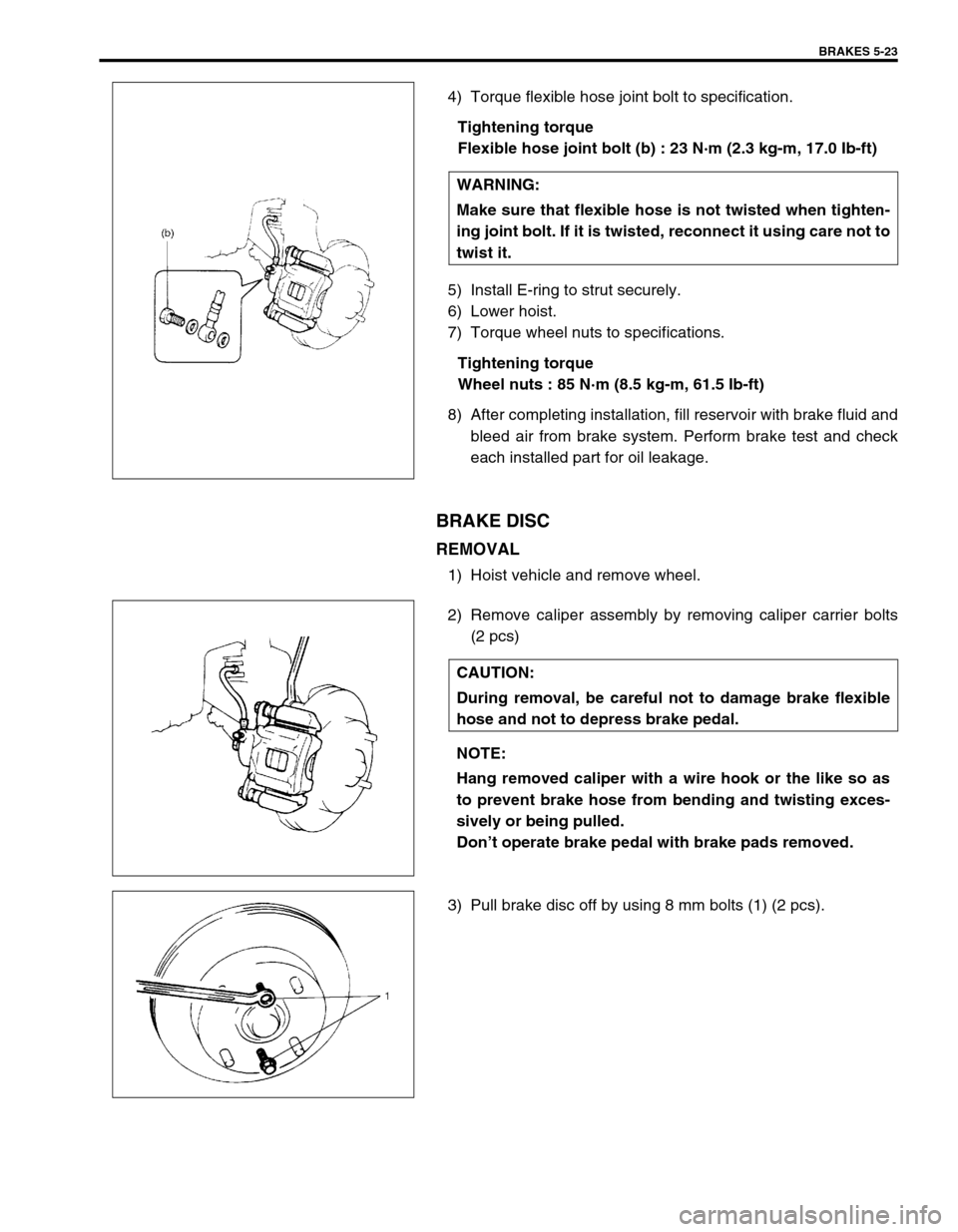
4) Torque flexible hose joint bolt to specification.
Tightening torque
Flexible hose joint bolt (b) : 23 N·m (2.3 kg-m, 17.0 Ib-ft)
5) Install E-ring to strut securely.
6) Lower hoist.
7) Torque wheel nuts to specifications.
Tightening torque
Wheel nuts : 85 N·m (8.5 kg-m, 61.5 Ib-ft)
8) After completing installation, fill reservoir with brake fluid and
bleed air from brake system. Perform brake test and check
each installed part for oil leakage.
BRAKE DISC
REMOVAL
1) Hoist vehicle and remove wheel.
2) Remove caliper assembly by removing caliper carrier bolts
(2 pcs)
3) Pull brake disc off by using 8 mm bolts (1) (2 pcs).WARNING:
Make sure that flexible hose is not twisted when tighten-
ing joint bolt. If it is twisted, reconnect it using care not to
twist it.
CAUTION:
During removal, be careful not to damage brake flexible
hose and not to depress brake pedal.
NOTE:
Hang removed caliper with a wire hook or the like so as
to prevent brake hose from bending and twisting exces-
sively or being pulled.
Don’t operate brake pedal with brake pads removed.
Page 297 of 698
5-24 BRAKES
INSPECTION
Using magnetic stand and with dial gauge positioned at
about 10 mm (0.39 in.) inward from periphery of disc, mea-
sure deflection of disc.
If limit value is exceeded, replace correct or replace.
Disc deflection
Limit : 0.10 mm (0.004 in.) max.
Special tool
(A) : 09900-20606
(B) : 09900-20701
Using micrometer, measure thickness of brake disc.
If limit value is exceeded, replace brake disc.
Brake disc thickness
Standard : 17.0 mm (0.67 in.)
Limit : 15.0 mm (0.59 in.)
INSTALLATION
1) Install disc to wheel hub.
2) Install caliper assembly to steering knuckle.
3) Torque caliper carrier bolts to specification.
Tightening torque
Caliper carrier bolts (a) : 85 N·m (8.5 kg-m, 61.5 Ib-ft)
4) Torque front wheel nuts to specification.
Tightening torque
Wheel nuts (b) : 85 N·m (8.5 kg-m, 61.5 Ib-ft)
5) Upon completion of installation, perform brake test.