Page 2 of 118

Downloaded from www.Manualslib.com manuals search engine Contents
Page
07
10
11
12
VALUES AND SETTINGS
Capacities - Grades 07-1
Accessories belt tension 07-2
Checking the accessories belt tension 07-3
Tightening the cylinder head 07-5
Tyres and wheels 07-6
Brakes 07-7
Brake compensator 07-8
Underbody height 07-9
Front axle angle checking values 07-11
Rear axle angle checking values 07-13
ENGINE AND PERIPHERALS
Identification 10-1
Oil pressure 10-2
Engine and transmission assembly 10-3
Sump 10-8
TOP AND FRONT OF ENGINE
Timing belt 11-1
Cylinder head gasket 11-6
FUEL MIXTURE
Air inlet 12-1
TURBOCHARGING
Pressure regulating valve 12-2
Pressure adjustment 12-3
Turbocharger 12-4
Air-air exchanger 12-7
Manifolds 12-9
Priming catalytic converter 12-12Page
13
14
DIESEL EQUIPMENT
Technical specifications 13-1
Special features 13-3
Cleanliness 13-6
Location of components 13-9
Injection warning light 13-12
Immobiliser function 13-13
Injection programming/ air conditioning 13-14
Idle speed correction13-16
Pre-postheating control 13-17
Heater plugs 13-18
Thermoplunger 13-19
Low pressure pump (supercharging
pump)13-21
Fuel filter 13-22
High pressure pump 13-23
Injector gallery 13-27
Injectors 13-32
Checking diesel pressure and flow 13-37
Pressure sensor 13-38
Pressure regulator 13-39
Accelerator potentiometer 13-40
Centralised coolant temperature
management 13-41
Computer 13-42
ANTIPOLLUTION
Oil vapour rebreathing 14-1
Exhaust gas recirculation 14-2
Page 18 of 118
Downloaded from www.Manualslib.com manuals search engine ENGINE AND PERIPHERALS
Oil pressure
10
10-2
Oil pressure
CHECKING
The oil pressure should be checked when the engine
is warm (approximately 80 °C).
Contents of kit Mot. 836-05.
USE
C + F
Connect the pressure gauge in place of the oil
pressure switch.
Oil pressure
1000 rpm 1.2 bar
3000 rpm 3.5 barsSPECIAL TOOLING REQUIRED
Mot. 836-05 Boxed kit for measuring oil
pressure
ESSENTIAL SPECIAL TOOLING
22 mm long socket
87363R1
Page 37 of 118

Downloaded from www.Manualslib.com manuals search engine TOP AND FRONT OF ENGINE
Cylinder head gasket
11
11-11
CLEANING
It is very important not to scratch the gasket faces
of any aluminium component.
Use the Décapjoint product to dissolve any part of the
gasket which remains attached.
W ear gloves whilst carrying out the following
operation.
– Apply the product to the parts to be cleaned; wait
about ten minutes, then remove it using a wooden
spatula.
W e must draw your attention to the care which
must be taken during this operation, to prevent
any foreign bodies from being introduced into the
oil ways (ducts located in the cylinder block and in
the cylinder head).
CHECKING THE GASKET FACE
Check for gasket face bow using a straight edge and a
set of shims.
Maximum deformation: 0.05 mm.
No regrinding of the cylinder head is permitted.
Check the cylinder head for cracks.Checking piston protrusion
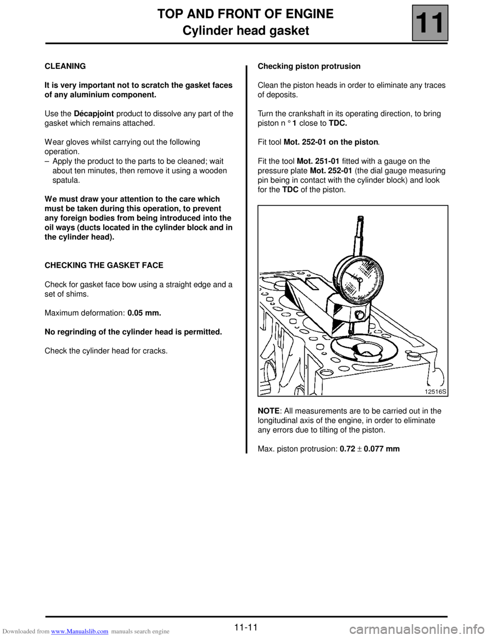
Clean the piston heads in order to eliminate any traces
of deposits.
Turn the crankshaft in its operating direction, to bring
piston n ° 1 close to TDC.
Fit tool Mot. 252-01 on the piston.
Fit the tool Mot. 251-01 fitted with a gauge on the
pressure plate Mot. 252-01 (the dial gauge measuring
pin being in contact with the cylinder block) and look
for the TDC of the piston.
NOTE: All measurements are to be carried out in the
longitudinal axis of the engine, in order to eliminate
any errors due to tilting of the piston.
Max. piston protrusion: 0.72 ± 0.077 mm
12516S
Page 95 of 118
Downloaded from www.Manualslib.com manuals search engine ANTIPOLLUTION
Oil vapour rebreathing
14
14-1
114ANTIPOLLUTION
Oil vapour rebreathing
CIRCUIT DIAGRAM
1Engine
2Oil separator
3Air filter unit
4Inlet manifold
CHECKING
To ensure the correct operation of the anti-pollution
system, the oil vapour rebreathing circuit must be kept
clean and in good condition.AOil vapour rebreathing pipe for the bottom of engine
BOil vapour rebreathing pipe for the top of engine
COil separator
DOil vapour rebreathing pipe linked to the intake
pipes
13042R
DI1322