Page 3 of 118
Downloaded from www.Manualslib.com manuals search engine Contents
Page
16
19
21
62
STARTING - CHARGING
Alternator 16-1
Starter 16-4
COOLING SYSTEM
Filling - bleeding 19-1
Diagram 19-2
Thermoplunger unit 19-3
Radiator 19-4
Water pump 19-5
ENGINE MOUNTING
Suspended engine mounting 19-6
Exhaust
Catalytic converter 19-7
MANUAL GEARBOX
Identification 21-1
Gears 21-1
Capacity - Lubricants 21-2
AIR CONDITIONING
General 62-1
Compressor 62-2
Dehydration canister 62-3
Condenser 62-4
Pressure relief valve 62-5
Connecting hoses 62-6
Page 5 of 118
Downloaded from www.Manualslib.com manuals search engine VALUES AND SETTINGS
Accessories belt tensioning
07
07-2
WITHOUT AIR
CONDITIONING
Accessories belt tensioning
ALTERNATOR AND POWER ASSISTED STEERING
Fitting tension (in Hertz): 188 ± 5
See Technical Note 3247A for the procedure for using
the tension measuring tool Mot. 1505.
A Crankshaft
B Alternator
C Power assisted steering pump
E Water pump
→ Tension checking point
98751R1
Page 36 of 118
Downloaded from www.Manualslib.com manuals search engine TOP AND FRONT OF ENGINE
Cylinder head gasket
11
11-10
– the low pressure pump connector,
– the bolts (1) and (2),
– the alternator mounting bolts and remove the
alternator, then remove the bolts (3).
Loosen the exhaust pipe clamp mounting.
Remove:
– the catalytic converter mountings on the pre-catalytic
converter,
– the pre-catalytic converter stay (1),
– the mounting (6),
– the oil supply pipe at (7) and remove towards the
bulkhead,
– the pre-catalytic converter mountings to the turbo,
– the catalytic converter removing the engine towards
the cooling system,
– the oil return pipe (8),– the bolt (9) and loosen the other mounting bolts on
the lower timing cover without removing them,
– cylinder head bolts.
Release the cylinder head by setting aside the lower
part of the camshaft housing, without causing the
cylinder head to turn, since this is centred by the two
dowels.
PRF1103
16155R
16156R2
12521-1R3
Page 98 of 118
Downloaded from www.Manualslib.com manuals search engine STARTING - CHARGING
Alternator
16
116STARTING - CHARGING
Alternator
IDENTIFICATION
CHECKING
After 15 minutes warming up at a voltage of 13.5 volts. Type Engine Alternator Current
XA0 5 F9Q 732
SG 10 B010
SG 10 B011
A13VI252
A11VI88120 A
80 A
75 A
Rpm. 75 Amps 80 Amps 120 Amps
1 000 40 54 -
1 500 - - 26
2 000 68 75 -
3 000 71 80 -
4 000 72 82 94
6 000 - - 105
16-1
Page 99 of 118

Downloaded from www.Manualslib.com manuals search engine STARTING - CHARGING
Alternator
16
16-2
REMOVAL
Put the vehicle on a 2 post lift.
Disconnect the battery as well as all electrical
connections on the alternator.
Separate the diesel filter from its mounting and
remove.
Unclip the power steering reservoir.
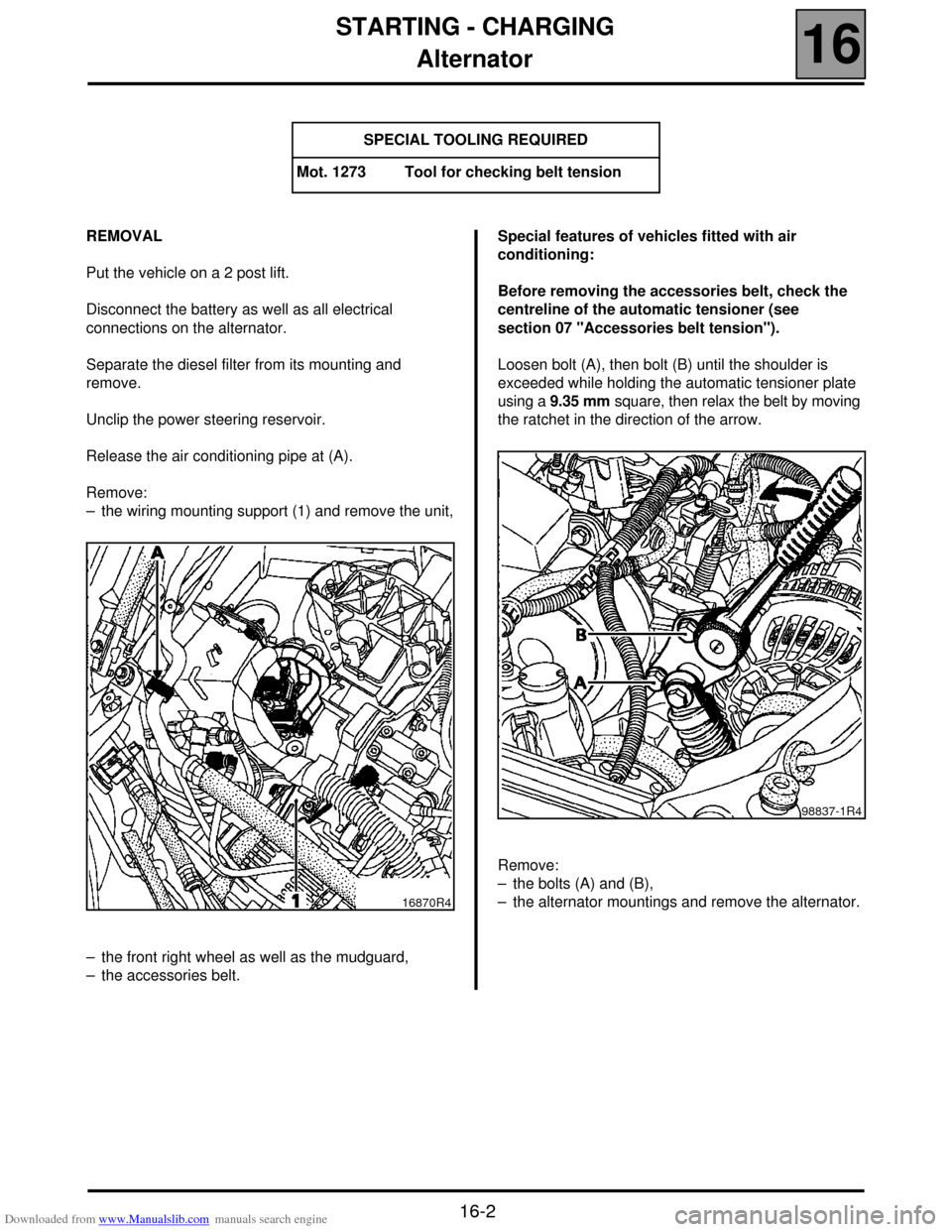
Release the air conditioning pipe at (A).
Remove:
– the wiring mounting support (1) and remove the unit,
– the front right wheel as well as the mudguard,
– the accessories belt.Special features of vehicles fitted with air
conditioning:
Before removing the accessories belt, check the
centreline of the automatic tensioner (see
section 07 "Accessories belt tension").
Loosen bolt (A), then bolt (B) until the shoulder is
exceeded while holding the automatic tensioner plate
using a 9.35 mm square, then relax the belt by moving
the ratchet in the direction of the arrow.
Remove:
– the bolts (A) and (B),
– the alternator mountings and remove the alternator. SPECIAL TOOLING REQUIRED
Mot. 1273 Tool for checking belt tension
16870R4
98837-1R4
Page 100 of 118
Downloaded from www.Manualslib.com manuals search engine STARTING - CHARGING
Alternator
16
16-3
REFITTING (special notes)
Refit in reverse order to removal.
The belts on vehicles fitted with air conditioning are
tensioned by bringing the automatic tensioner plate to
a stop at bolt (B), without forcing it, using a 9.35 mm
square.
See section 07 "Accessories belt tension" for the
belt tension value for vehicles without air conditioning.
NOTE: never refit a belt once it has been removed,
but replace it.
98837-1R1
Page 113 of 118
Downloaded from www.Manualslib.com manuals search engine AIR CONDITIONING
Compressor
62
62-2
SCENIC Compressor
REMOVAL
Drain the R134a refrigerant circuit (refer to the
procedure described in the "Air conditioning" manual).
Disconnect the battery.
Remove:
– the cooling assembly (see section 19 ),
– the alternator (see section 16),
– the R134a refrigerant pipes retaining bolt,
– the four compressor mounting bolts.REFITTING
Refitting is the reverse of removal.
Tighten the R134a refrigerant pipes retaining bolt on
the compressor to 3 daN.m.
Fill the R134a refrigerant circuit using the filling
equipment.
IMPORTANT:
When replacing the existing compressor with a new
compressor, it is essential to drain some of the oil from
the new compressor, so that the amount of oil in the
new compressor corresponds to the amount of oil
drained from the oil compressor.
99211S
Oil drained
new
compressor=Oil
in the new
compressor-Oil remaining
in the old
compressor