Page 2 of 118

Downloaded from www.Manualslib.com manuals search engine Contents
Page
07
10
11
12
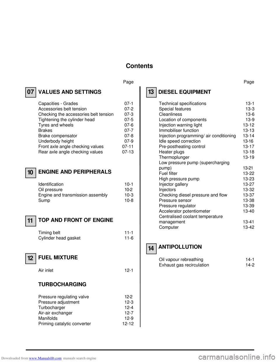
VALUES AND SETTINGS
Capacities - Grades 07-1
Accessories belt tension 07-2
Checking the accessories belt tension 07-3
Tightening the cylinder head 07-5
Tyres and wheels 07-6
Brakes 07-7
Brake compensator 07-8
Underbody height 07-9
Front axle angle checking values 07-11
Rear axle angle checking values 07-13
ENGINE AND PERIPHERALS
Identification 10-1
Oil pressure 10-2
Engine and transmission assembly 10-3
Sump 10-8
TOP AND FRONT OF ENGINE
Timing belt 11-1
Cylinder head gasket 11-6
FUEL MIXTURE
Air inlet 12-1
TURBOCHARGING
Pressure regulating valve 12-2
Pressure adjustment 12-3
Turbocharger 12-4
Air-air exchanger 12-7
Manifolds 12-9
Priming catalytic converter 12-12Page
13
14
DIESEL EQUIPMENT
Technical specifications 13-1
Special features 13-3
Cleanliness 13-6
Location of components 13-9
Injection warning light 13-12
Immobiliser function 13-13
Injection programming/ air conditioning 13-14
Idle speed correction13-16
Pre-postheating control 13-17
Heater plugs 13-18
Thermoplunger 13-19
Low pressure pump (supercharging
pump)13-21
Fuel filter 13-22
High pressure pump 13-23
Injector gallery 13-27
Injectors 13-32
Checking diesel pressure and flow 13-37
Pressure sensor 13-38
Pressure regulator 13-39
Accelerator potentiometer 13-40
Centralised coolant temperature
management 13-41
Computer 13-42
ANTIPOLLUTION
Oil vapour rebreathing 14-1
Exhaust gas recirculation 14-2
Page 12 of 118
Downloaded from www.Manualslib.com manuals search engine VALUES AND SETTINGS
Underbody height
07
07-9
Underbody height
The difference between the right-hand side and the left-hand side of the same axle of a vehicle must not exceed
5 mm, the driver's side always being higher.
Any alteration to the underbody height also requires adjustment of the brake compensator and of the headlights.Typeat the front
H1 - H2 = ... mm
± 7.5 mmat the rear
H4 - H5 = ... mm
± 7.5 mmDimension X (mm)
D and G
± 0.5 mm
BA05 104 22 496
JA05 102 27 512
98336R
Page 13 of 118
Downloaded from www.Manualslib.com manuals search engine VALUES AND SETTINGS
Underbody height
07
07-10
MEASUREMENT POINTS
Dimension H5 is measured from the axis of the
suspension bar.
99656R1
88636-4R
Page 109 of 118

Downloaded from www.Manualslib.com manuals search engine EXHAUST
Catalytic converter
19
19-7
1419 EXHAUST
Catalytic converter
Disconnect the battery and put the vehicle on a two
post lift.
Fit a flywheel immobiliser.
Loosen the catalytic converter/precatalytic converter
mountings.
Fit tool Tav. 1233-01 replacing the bolts of the sub-
frame one by one.Remove:
– the bolts of the sub-frame tie-rods,
– the nut and eccentric bolt of the steering shaft
yoke (1),
– the torque reaction arm.
Lower the sub-frame to a height of 40 mm at the front
and 60 mm at the rear.
Remove the exhaust mounting clip.
Remove the mounting nuts of the catalytic converter
and remove it, taking care not to damage the heat
shields.
REFITTING
Proceed in the reverse order from removal.
WARNING: all damaged heat shields must be
replaced to prevent the risk of fire. TIGHTENING TORQUES (in daN.m)
Engine tie bar bolt 6.2
Steering shaft yoke bolts 3
Engine sub-frame bolts
–front ∅ 10
–rear ∅ 12 6.2
10.5
Three point flange nuts 2
Sub-frame - side member tie rod bolts 3
15870R
97390-1R2