Page 242 of 1033
tion due to receiving external noise, degraded operation
of ICs, etc.
+Keep ECM parts and harnesses dry.
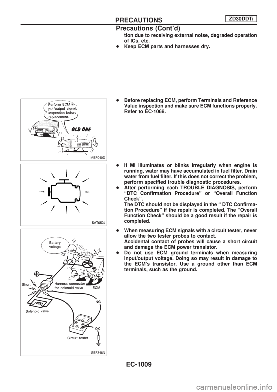
+Before replacing ECM, perform Terminals and Reference
Value inspection and make sure ECM functions properly.
Refer to EC-1068.
+If MI illuminates or blinks irregularly when engine is
running, water may have accumulated in fuel filter. Drain
water from fuel filter. If this does not correct the problem,
perform specified trouble diagnostic procedures.
+After performing each TROUBLE DIAGNOSIS, perform
ªDTC Confirmation Procedureº or ªOverall Function
Checkº.
The DTC should not be displayed in the ª DTC Confirma-
tion Procedureº if the repair is completed. The ªOverall
Function Checkº should be a good result if the repair is
completed.
+When measuring ECM signals with a circuit tester, never
allow the two tester probes to contact.
Accidental contact of probes will cause a short circuit
and damage the ECM power transistor.
+Do not use ECM ground terminals when measuring
input/output voltage. Doing so may result in damage to
the ECM's transistor. Use a ground other than ECM
terminals, such as the ground.
MEF040D
SAT652J
SEF348N
PRECAUTIONSZD30DDTi
Precautions (Cont'd)
EC-1009
Page 255 of 1033
Crankcase Ventilation System
DESCRIPTION
In this system, blow-by gas is sucked into the air inlet pipe after
oil separation by oil separator in the rocker cover.
INSPECTION
Ventilation hose
1. Check hoses and hose connections for leaks.
2. Disconnect all hoses and clean with compressed air. If any
hose cannot be freed of obstructions, replace.
JEF224Z
SEC692
ENGINE AND EMISSION BASIC CONTROL SYSTEM
DESCRIPTIONZD30DDTi
EC-1022
Page 260 of 1033
REMOVAL
1. Remove the following:
+Engine coolant draining
+Charge air cooler
+Air inlet pipe
+Throttle body
+Rocker cover
+Oil level gauge guide
+EGR guide tube
+EGR volume control solenoid valve
+Fuel hose
+Injection tube
+Radiator upper hose
+Radiator shroud
+Cooling fan
+Drive belt
+Vacuum pipe
+Vacuum pump
2. Move the power steering pump.
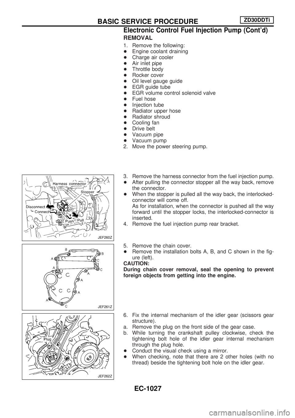
3. Remove the harness connector from the fuel injection pump.
+After pulling the connector stopper all the way back, remove
the connector.
+When the stopper is pulled all the way back, the interlocked-
connector will come off.
As for installation, when the connector is pushed all the way
forward until the stopper locks, the interlocked-connector is
inserted.
4. Remove the fuel injection pump rear bracket.
5. Remove the chain cover.
+Remove the installation bolts A, B, and C shown in the fig-
ure (left).
CAUTION:
During chain cover removal, seal the opening to prevent
foreign objects from getting into the engine.
6. Fix the internal mechanism of the idler gear (scissors gear
structure).
a. Remove the plug on the front side of the gear case.
b. While turning the crankshaft pulley clockwise, check the
tightening bolt hole of the idler gear internal mechanism
through the plug hole.
+Conduct the visual check using a mirror.
+When checking, note that there are 2 other holes (with no
thread) beside the tightening bolt hole on the idler gear.
JEF260Z
JEF261Z
JEF262Z
BASIC SERVICE PROCEDUREZD30DDTi
Electronic Control Fuel Injection Pump (Cont'd)
EC-1027
Page 262 of 1033
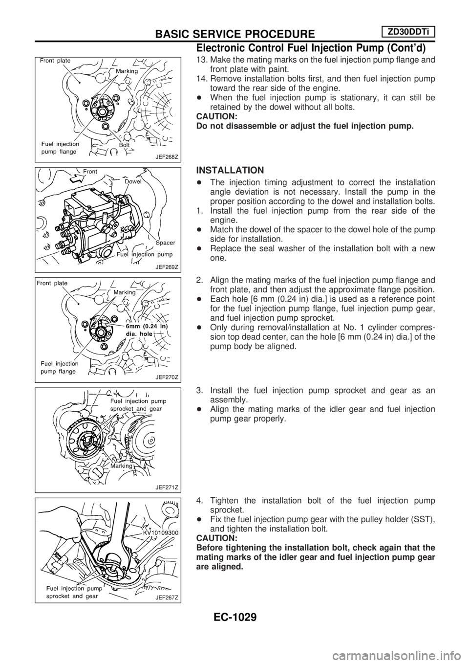
13. Make the mating marks on the fuel injection pump flange and
front plate with paint.
14. Remove installation bolts first, and then fuel injection pump
toward the rear side of the engine.
+When the fuel injection pump is stationary, it can still be
retained by the dowel without all bolts.
CAUTION:
Do not disassemble or adjust the fuel injection pump.
INSTALLATION
+The injection timing adjustment to correct the installation
angle deviation is not necessary. Install the pump in the
proper position according to the dowel and installation bolts.
1. Install the fuel injection pump from the rear side of the
engine.
+Match the dowel of the spacer to the dowel hole of the pump
side for installation.
+Replace the seal washer of the installation bolt with a new
one.
2. Align the mating marks of the fuel injection pump flange and
front plate, and then adjust the approximate flange position.
+Each hole [6 mm (0.24 in) dia.] is used as a reference point
for the fuel injection pump flange, fuel injection pump gear,
and fuel injection pump sprocket.
+Only during removal/installation at No. 1 cylinder compres-
sion top dead center, can the hole [6 mm (0.24 in) dia.] of the
pump body be aligned.
3. Install the fuel injection pump sprocket and gear as an
assembly.
+Align the mating marks of the idler gear and fuel injection
pump gear properly.
4. Tighten the installation bolt of the fuel injection pump
sprocket.
+Fix the fuel injection pump gear with the pulley holder (SST),
and tighten the installation bolt.
CAUTION:
Before tightening the installation bolt, check again that the
mating marks of the idler gear and fuel injection pump gear
are aligned.
JEF268Z
JEF269Z
JEF270Z
JEF271Z
JEF267Z
BASIC SERVICE PROCEDUREZD30DDTi
Electronic Control Fuel Injection Pump (Cont'd)
EC-1029
Page 266 of 1033
2. Change the diagnostic test mode from Mode II to Mode I by using the data link connector. (See
EC-1035.)
The emission related diagnostic information in the ECM can be erased by changing the diagnostic test mode.
+If the battery is disconnected, the emission-related diagnostic information will be lost after
approx. 24 hours.
+Erasing the emission-related diagnostic information using CONSULT-II is easier and quicker than
switching the diagnostic test mode using the data link connector.
NATS (Nissan Anti-Theft System)
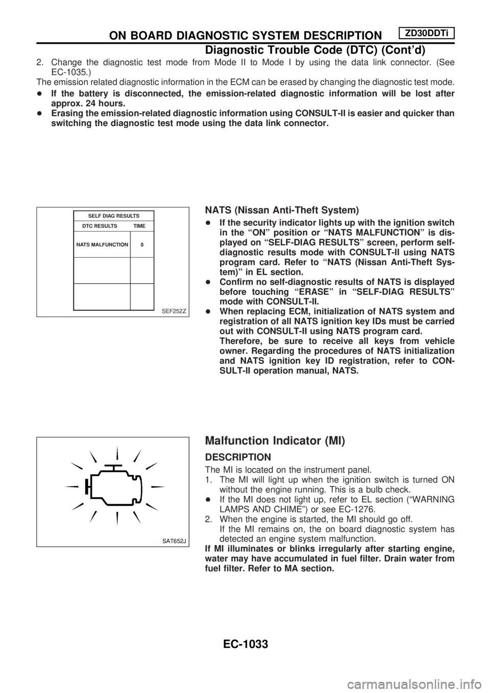
+If the security indicator lights up with the ignition switch
in the ªONº position or ªNATS MALFUNCTIONº is dis-
played on ªSELF-DIAG RESULTSº screen, perform self-
diagnostic results mode with CONSULT-II using NATS
program card. Refer to ªNATS (Nissan Anti-Theft Sys-
tem)º in EL section.
+Confirm no self-diagnostic results of NATS is displayed
before touching ªERASEº in ªSELF-DIAG RESULTSº
mode with CONSULT-II.
+When replacing ECM, initialization of NATS system and
registration of all NATS ignition key IDs must be carried
out with CONSULT-II using NATS program card.
Therefore, be sure to receive all keys from vehicle
owner. Regarding the procedures of NATS initialization
and NATS ignition key ID registration, refer to CON-
SULT-II operation manual, NATS.
Malfunction Indicator (MI)
DESCRIPTION
The MI is located on the instrument panel.
1. The MI will light up when the ignition switch is turned ON
without the engine running. This is a bulb check.
+If the MI does not light up, refer to EL section (ªWARNING
LAMPS AND CHIMEº) or see EC-1276.
2. When the engine is started, the MI should go off.
If the MI remains on, the on board diagnostic system has
detected an engine system malfunction.
If MI illuminates or blinks irregularly after starting engine,
water may have accumulated in fuel filter. Drain water from
fuel filter. Refer to MA section.
SEF252Z
SAT652J
ON BOARD DIAGNOSTIC SYSTEM DESCRIPTIONZD30DDTi
Diagnostic Trouble Code (DTC) (Cont'd)
EC-1033
Page 267 of 1033
On board diagnostic system function
The on board diagnostic system has the following three func-
tions.
Diagnostic Test Mode KEY and ENG. Status Function Explanation of Function
Mode I Ignition switch in ON
position
Engine stopped
BULB CHECK This function checks the MI bulb for damage
(blown, open circuit, etc.).
If the MI does not come on, check MI circuit.
(See EC-1276.)
Engine running
MALFUNCTION
WARNINGThis is a usual driving condition. When ECM
detects a malfunction, the MI will light up to
inform the driver that a malfunction has been
detected.
Mode II Ignition switch in ON
position
Engine stopped
SELF-DIAGNOSTIC RESULTS This function allows DTCs to be read.
ON BOARD DIAGNOSTIC SYSTEM DESCRIPTIONZD30DDTi
Malfunction Indicator (MI) (Cont'd)
EC-1034
Page 275 of 1033
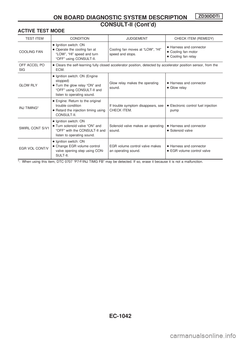
ACTIVE TEST MODE
TEST ITEM CONDITION JUDGEMENT CHECK ITEM (REMEDY)
COOLING FAN+Ignition switch: ON
+Operate the cooling fan at
ªLOWº, ªHIº speed and turn
ªOFFº using CONSULT-II.Cooling fan moves at ªLOWº, ªHIº
speed and stops.+Harness and connector
+Cooling fan motor
+Cooling fan relay
OFF ACCEL PO
SIG+Clears the self-learning fully closed accelerator position, detected by accelerator position sensor, from the
ECM.
GLOW RLY+Ignition switch: ON (Engine
stopped)
+Turn the glow relay ªONº and
ªOFFº using CONSULT-II and
listen to operating sound.Glow relay makes the operating
sound.+Harness and connector
+Glow relay
INJ TIMING*+Engine: Return to the original
trouble condition
+Retard the injection timing using
CONSULT-II.If trouble symptom disappears, see
CHECK ITEM.+Electronic control fuel injection
pump
SWIRL CONT S/V1+Ignition switch: ON
+Turn solenoid valve ªONº and
ªOFFº with the CONSULT-II and
listen to operating sound.Solenoid valve makes an operating
sound.+Harness and connector
+Solenoid valve
EGR VOL CONT/V+Ignition switch: ON
+Change EGR volume control
valve opening step using CON-
SULT-II.EGR volume control valve makes
an operating sound.+Harness and connector
+EGR volume control valve
*: When using this item, DTC 0707 ªP7zF/INJ TIMG FBº may be detected. If so, erase it because it is not a malfunction.
ON BOARD DIAGNOSTIC SYSTEM DESCRIPTIONZD30DDTi
CONSULT-II (Cont'd)
EC-1042
Page 278 of 1033
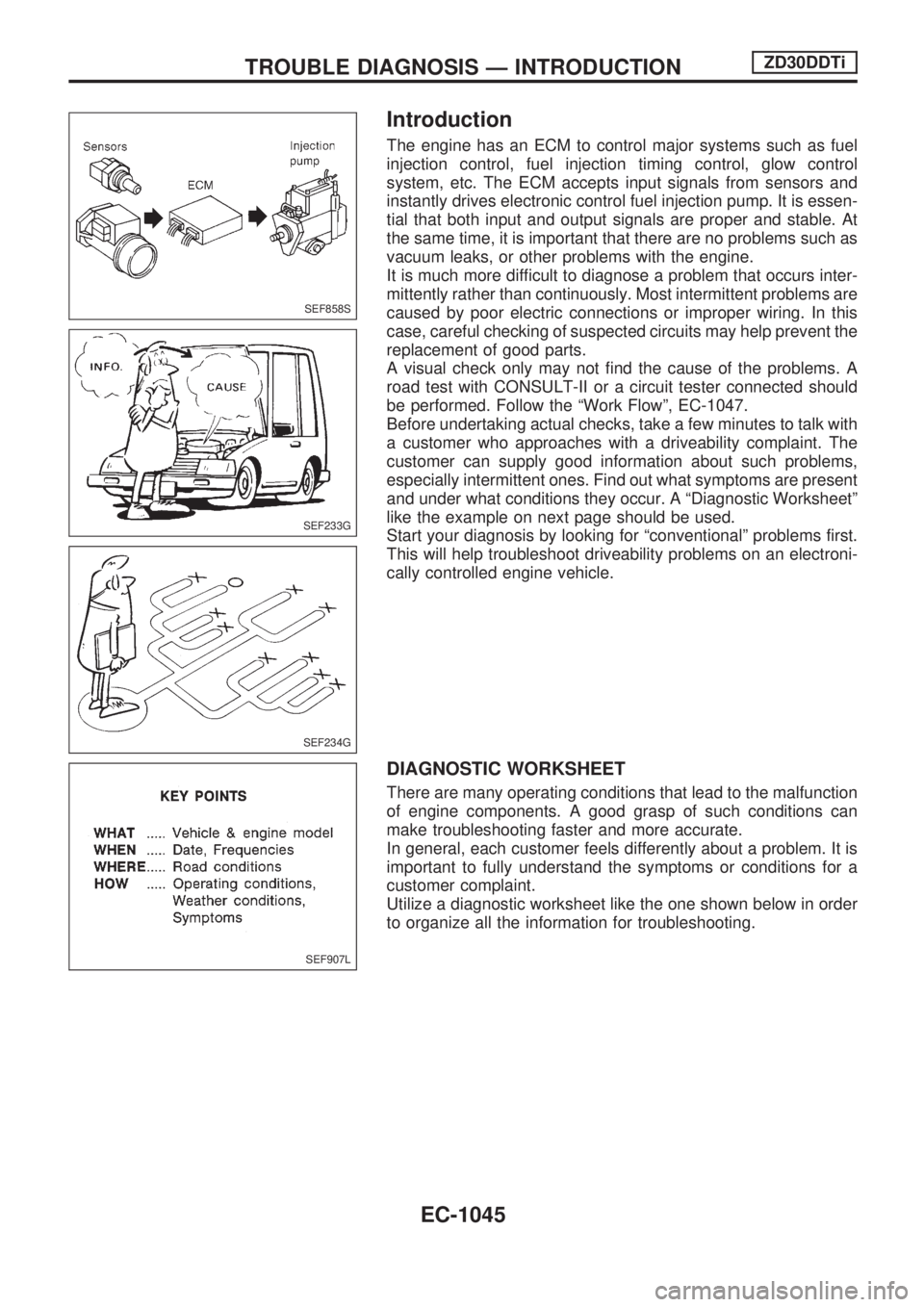
Introduction
The engine has an ECM to control major systems such as fuel
injection control, fuel injection timing control, glow control
system, etc. The ECM accepts input signals from sensors and
instantly drives electronic control fuel injection pump. It is essen-
tial that both input and output signals are proper and stable. At
the same time, it is important that there are no problems such as
vacuum leaks, or other problems with the engine.
It is much more difficult to diagnose a problem that occurs inter-
mittently rather than continuously. Most intermittent problems are
caused by poor electric connections or improper wiring. In this
case, careful checking of suspected circuits may help prevent the
replacement of good parts.
A visual check only may not find the cause of the problems. A
road test with CONSULT-II or a circuit tester connected should
be performed. Follow the ªWork Flowº, EC-1047.
Before undertaking actual checks, take a few minutes to talk with
a customer who approaches with a driveability complaint. The
customer can supply good information about such problems,
especially intermittent ones. Find out what symptoms are present
and under what conditions they occur. A ªDiagnostic Worksheetº
like the example on next page should be used.
Start your diagnosis by looking for ªconventionalº problems first.
This will help troubleshoot driveability problems on an electroni-
cally controlled engine vehicle.
DIAGNOSTIC WORKSHEET
There are many operating conditions that lead to the malfunction
of engine components. A good grasp of such conditions can
make troubleshooting faster and more accurate.
In general, each customer feels differently about a problem. It is
important to fully understand the symptoms or conditions for a
customer complaint.
Utilize a diagnostic worksheet like the one shown below in order
to organize all the information for troubleshooting.
SEF858S
SEF233G
SEF234G
SEF907L
TROUBLE DIAGNOSIS Ð INTRODUCTIONZD30DDTi
EC-1045