Page 113 of 1033
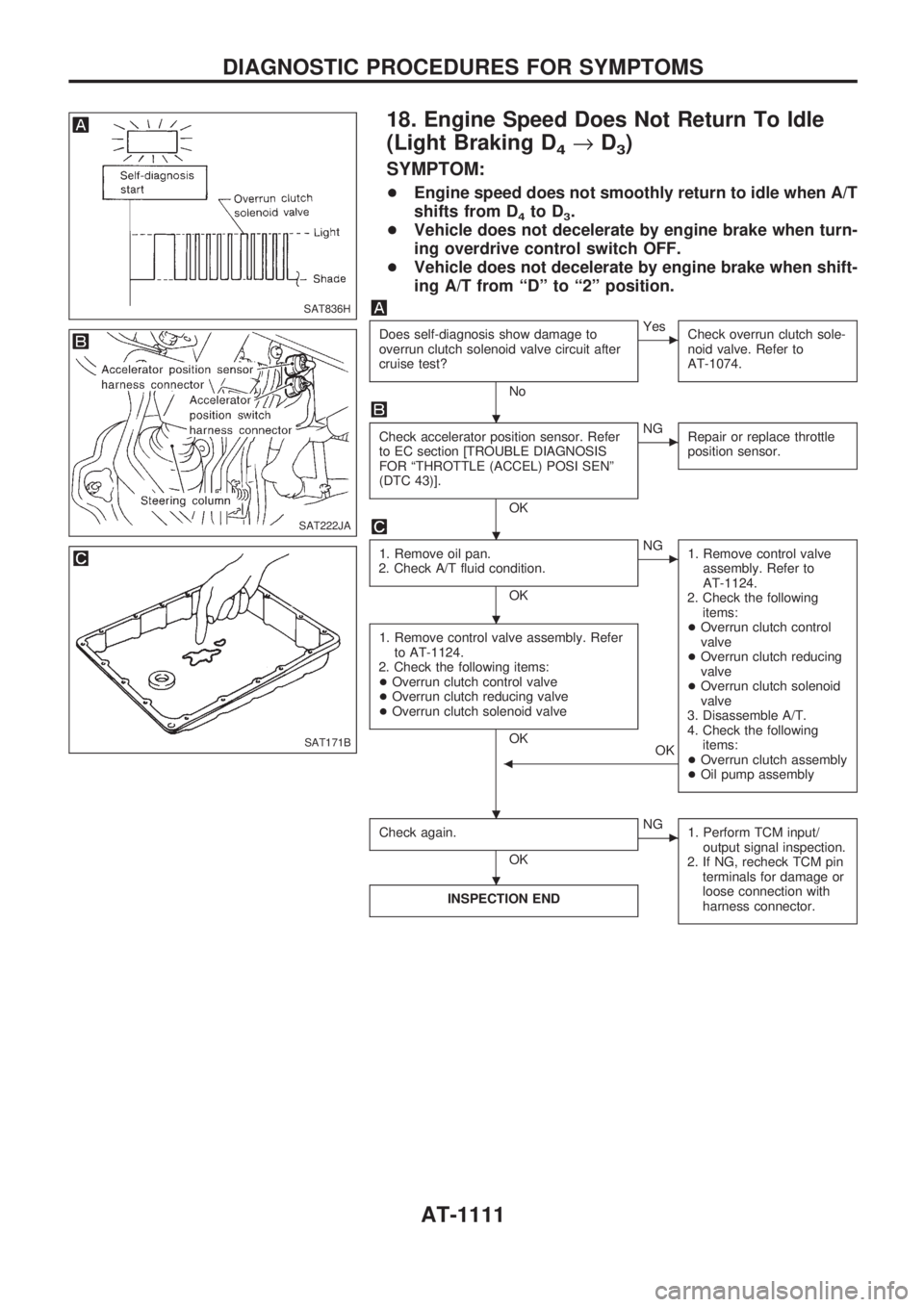
18. Engine Speed Does Not Return To Idle
(Light Braking D
4®D3)
SYMPTOM:
+Engine speed does not smoothly return to idle when A/T
shifts from D
4to D3.
+Vehicle does not decelerate by engine brake when turn-
ing overdrive control switch OFF.
+Vehicle does not decelerate by engine brake when shift-
ing A/T from ªDº to ª2º position.
Does self-diagnosis show damage to
overrun clutch solenoid valve circuit after
cruise test?
No
cYes
Check overrun clutch sole-
noid valve. Refer to
AT-1074.
Check accelerator position sensor. Refer
to EC section [TROUBLE DIAGNOSIS
FOR ªTHROTTLE (ACCEL) POSI SENº
(DTC 43)].
OK
cNG
Repair or replace throttle
position sensor.
1. Remove oil pan.
2. Check A/T fluid condition.
OK
cNG
1. Remove control valve
assembly. Refer to
AT-1124.
2. Check the following
items:
+Overrun clutch control
valve
+Overrun clutch reducing
valve
+Overrun clutch solenoid
valve
3. Disassemble A/T.
4. Check the following
items:
+Overrun clutch assembly
+Oil pump assembly
1. Remove control valve assembly. Refer
to AT-1124.
2. Check the following items:
+Overrun clutch control valve
+Overrun clutch reducing valve
+Overrun clutch solenoid valve
OK
OK
b
Check again.
OK
cNG
1. Perform TCM input/
output signal inspection.
2. If NG, recheck TCM pin
terminals for damage or
loose connection with
harness connector.
INSPECTION END
SAT836H
SAT222JA
SAT171B
.
.
.
. .
.
DIAGNOSTIC PROCEDURES FOR SYMPTOMS
AT-1111
Page 117 of 1033
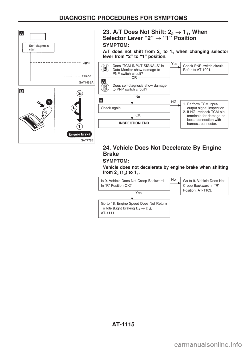
23. A/T Does Not Shift: 22®11, When
Selector Lever ª2º®ª1º Position
SYMPTOM:
A/T does not shift from 22to 11when changing selector
lever from ª2º to ª1º position.
Does ªTCM INPUT SIGNALSº in
Data Monitor show damage to
PNP switch circuit?
------------------------------------------------------------------------------------------------------------------------------------OR------------------------------------------------------------------------------------------------------------------------------------
Does self-diagnosis show damage
to PNP switch circuit?
No
cYes
Check PNP switch circuit.
Refer to AT-1091.
Check again.
OK
cNG
1. Perform TCM input/
output signal inspection.
2. If NG, recheck TCM pin
terminals for damage or
loose connection with
harness connector.
INSPECTION END
24. Vehicle Does Not Decelerate By Engine
Brake
SYMPTOM:
Vehicle does not decelerate by engine brake when shifting
from 2
2(12)to11.
Is 9. Vehicle Does Not Creep Backward
In ªRº Position OK?
Yes
cNo
Go to 9. Vehicle Does Not
Creep Backward In ªRº
Position, AT-1103.
Go to 18. Engine Speed Does Not Return
To Idle (Light Braking D
4®D3),
AT-1111.
SAT146BA
SAT778B
.
.
.
DIAGNOSTIC PROCEDURES FOR SYMPTOMS
AT-1115
Page 120 of 1033
Diagnostic Procedure
SYMPTOM 1:
+Selector lever cannot be moved from ªPº position with
key in ªONº position and brake pedal applied.
+Selector lever can be moved from ªPº position with key
in ªONº position and brake pedal released.
+Selector lever can be moved from ªPº position when key
is removed from key cylinder.
SYMPTOM 2:
Ignition key cannot be removed when selector lever is set to
ªPº position. It can be removed when selector lever is set to
any position except ªPº.
Check key interlock cable for damage.
OK
cNG
Repair key interlock cable.
Refer to ªKey Interlock
Cableº, AT-1121.
Check selector lever position for damage.
OK
cNG
Check selector lever.
Refer to ªON-VEHICLE
SERVICE Ð PNP Switch
and Manual Control Link-
age Adjustmentº.
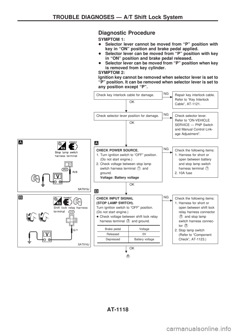
CHECK POWER SOURCE.
1. Turn ignition switch to ªOFFº position.
(Do not start engine.)
2. Check voltage between stop lamp
switch harness terminal
V1and
ground.
Voltage: Battery voltage
OK
cNG
Check the following items:
1. Harness for short or
open between battery
and stop lamp switch
harness terminal
V1
2. 10A fuse
CHECK INPUT SIGNAL
(STOP LAMP SWITCH).
Turn ignition switch to ªOFFº position.
(Do not start engine.)
+Check voltage between shift lock relay
harness terminal
V2and ground.
OK
cNG
Check the following items:
1. Harness for short or
open between shift lock
relay harness connector
V2and stop lamp
switch harness connec-
tor
V2
2. Stop lamp switch
(Refer to ªComponent
Checkº, AT-1123.)
VA
Brake pedal Voltage
Released 0V
Depressed Battery voltage
SAT915J
SAT916J
.
.
.
.
TROUBLE DIAGNOSES Ð A/T Shift Lock System
AT-1118
Page 121 of 1033
VA
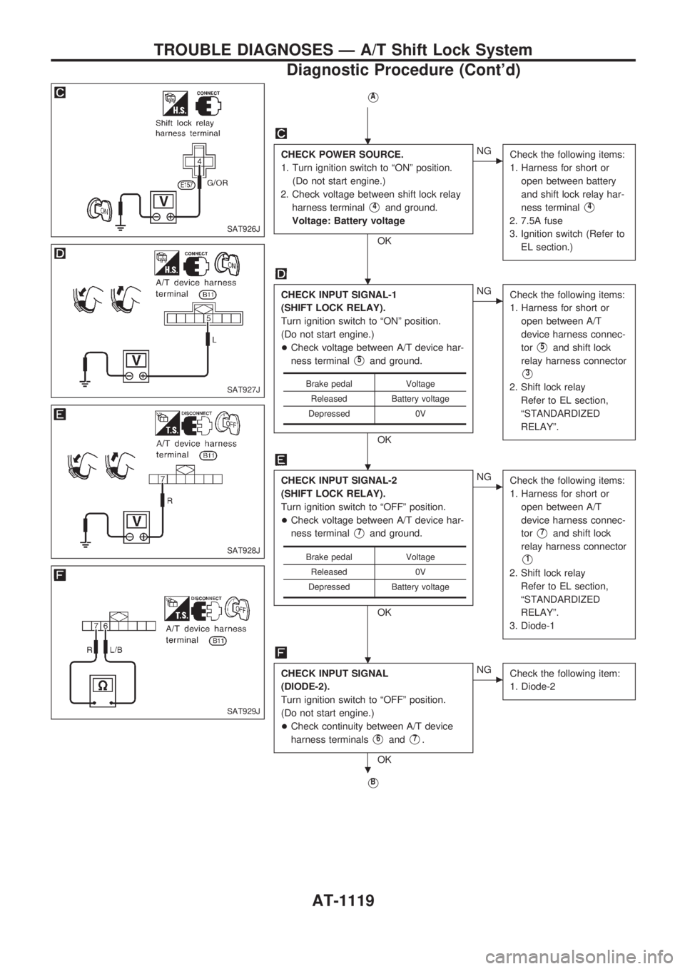
CHECK POWER SOURCE.
1. Turn ignition switch to ªONº position.
(Do not start engine.)
2. Check voltage between shift lock relay
harness terminal
V4and ground.
Voltage: Battery voltage
OK
cNG
Check the following items:
1. Harness for short or
open between battery
and shift lock relay har-
ness terminal
V4
2. 7.5A fuse
3. Ignition switch (Refer to
EL section.)
CHECK INPUT SIGNAL-1
(SHIFT LOCK RELAY).
Turn ignition switch to ªONº position.
(Do not start engine.)
+Check voltage between A/T device har-
ness terminal
V5and ground.
OK
cNG
Check the following items:
1. Harness for short or
open between A/T
device harness connec-
tor
V5and shift lock
relay harness connector
V3
2. Shift lock relay
Refer to EL section,
ªSTANDARDIZED
RELAYº.
CHECK INPUT SIGNAL-2
(SHIFT LOCK RELAY).
Turn ignition switch to ªOFFº position.
+Check voltage between A/T device har-
ness terminal
V7and ground.
OK
cNG
Check the following items:
1. Harness for short or
open between A/T
device harness connec-
tor
V7and shift lock
relay harness connector
V1
2. Shift lock relay
Refer to EL section,
ªSTANDARDIZED
RELAYº.
3. Diode-1
CHECK INPUT SIGNAL
(DIODE-2).
Turn ignition switch to ªOFFº position.
(Do not start engine.)
+Check continuity between A/T device
harness terminals
V6andV7.
OK
cNG
Check the following item:
1. Diode-2
VB
Brake pedal Voltage
Released Battery voltage
Depressed 0V
Brake pedal Voltage
Released 0V
Depressed Battery voltage
SAT926J
SAT927J
SAT928J
SAT929J
.
.
.
.
.
TROUBLE DIAGNOSES Ð A/T Shift Lock System
Diagnostic Procedure (Cont'd)
AT-1119
Page 122 of 1033
VB
CHECK GROUND CIRCUIT.
1. Turn ignition switch to ªOFFº position.
2. Disconnect A/T device harness con-
nector.
3. Check continuity between A/T device
harness terminal
V8and ground.
OK
cNG
Repair harness or connec-
tor.
CHECK PARK POSITION SWITCH.
(Refer to ªComponent Checkº, AT-1122.)
OK
cNG
Replace park position
switch.
CHECK SHIFT LOCK SOLENOID.
(Refer to ªComponent Checkº, AT-1122.)
OK
cNG
Replace shift lock sole-
noid.
Reconnect shift lock harness connector.
Turn ignition switch from ªOFFº to ªONº
position. (Do not start engine.)
Recheck shift lock operation.
OK
cNG
1. Perform A/T device
input/output signal
inspection test.
2. If NG, recheck harness
connector connection.
INSPECTION END
SAT917J
.
.
.
.
.
.
.
TROUBLE DIAGNOSES Ð A/T Shift Lock System
Diagnostic Procedure (Cont'd)
AT-1120
Page 127 of 1033
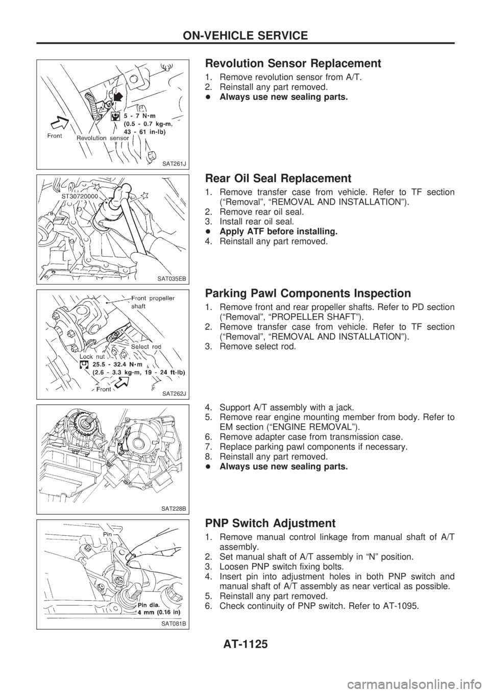
Revolution Sensor Replacement
1. Remove revolution sensor from A/T.
2. Reinstall any part removed.
+Always use new sealing parts.
Rear Oil Seal Replacement
1. Remove transfer case from vehicle. Refer to TF section
(ªRemovalº, ªREMOVAL AND INSTALLATIONº).
2. Remove rear oil seal.
3. Install rear oil seal.
+Apply ATF before installing.
4. Reinstall any part removed.
Parking Pawl Components Inspection
1. Remove front and rear propeller shafts. Refer to PD section
(ªRemovalº, ªPROPELLER SHAFTº).
2. Remove transfer case from vehicle. Refer to TF section
(ªRemovalº, ªREMOVAL AND INSTALLATIONº).
3. Remove select rod.
4. Support A/T assembly with a jack.
5. Remove rear engine mounting member from body. Refer to
EM section (ªENGINE REMOVALº).
6. Remove adapter case from transmission case.
7. Replace parking pawl components if necessary.
8. Reinstall any part removed.
+Always use new sealing parts.
PNP Switch Adjustment
1. Remove manual control linkage from manual shaft of A/T
assembly.
2. Set manual shaft of A/T assembly in ªNº position.
3. Loosen PNP switch fixing bolts.
4. Insert pin into adjustment holes in both PNP switch and
manual shaft of A/T assembly as near vertical as possible.
5. Reinstall any part removed.
6. Check continuity of PNP switch. Refer to AT-1095.
SAT261J
SAT035EB
SAT262J
SAT228B
SAT081B
ON-VEHICLE SERVICE
AT-1125
Page 130 of 1033
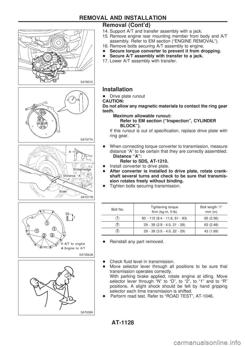
14. Support A/T and transfer assembly with a jack.
15. Remove engine rear mounting member from body and A/T
assembly. Refer to EM section (ªENGINE REMOVALº).
16. Remove bolts securing A/T assembly to engine.
+Secure torque converter to prevent it from dropping.
+Secure A/T assembly with transfer to a jack.
17. Lower A/T assembly with transfer.
Installation
+Drive plate runout
CAUTION:
Do not allow any magnetic materials to contact the ring gear
teeth.
Maximum allowable runout:
Refer to EM section (ªInspectionº, CYLINDER
BLOCKº).
If this runout is out of specification, replace drive plate with
ring gear.
+When connecting torque converter to transmission, measure
distance ªAº to be certain that they are correctly assembled.
Distance ªAº:
Refer to SDS, AT-1210.
+Install converter to drive plate.
+After converter is installed to drive plate, rotate crank-
shaft several turns and check to be sure that transmis-
sion rotates freely without binding.
+Tighten bolts securing transmission.
Bolt No.Tightening torque
Nzm (kg-m, ft-lb)Bolt length ª!º
mm (in)
V183 - 113 (8.4 - 11.6, 61 - 83) 65 (2.56)
V229 - 39 (2.9 - 4.0, 21 - 28) 63 (2.48)
V329 - 39 (3.0 - 4.0, 22 - 29) 43 (1.69)
+Reinstall any part removed.
+Check fluid level in transmission.
+Move selector lever through all positions to be sure that
transmission operates correctly.
With parking brake applied, rotate engine at idling. Move
selector lever through ªNº to ªDº, to ª2º, to ª1º and to ªRº
positions. A slight shock should be felt by hand gripping
selector each time transmission is shifted.
+Perform road test. Refer to ªROAD TESTº, AT-1046.
SAT801C
SAT977H
SAT017B
SAT266JB
SAT638A
REMOVAL AND INSTALLATION
Removal (Cont'd)
AT-1128
Page 136 of 1033
6. Place transmission into Tool with the control valve facing up.
7. Check foreign materials in oil pan to help determine cause of
malfunction. If the fluid is very dark, smells burned, or con-
tains foreign particles, the frictional material (clutches, band)
may need replacement. A tacky film that will not wipe clean
indicates varnish build up. Varnish can cause valves, servo,
and clutches to stick and may inhibit pump pressure.
+If frictional material is detected, replace radiator after
repair of A/T. Refer to LC section (ªRadiatorº, ªENGINE
COOLING SYSTEMº).
8. Remove torque converter clutch solenoid valve and A/T fluid
temperature sensor connectors.
+Be careful not to damage connector.
9. Remove oil strainer.
a. Remove oil strainer from control valve assembly.
Then remove O-ring from oil strainer.
b. Check oil strainer screen for damage.
SAT522GA
SAT171B
SAT024BA
SAT008B
SAT025B
DISASSEMBLY
AT-1134