Page 611 of 1033

System Description
The rear window defogger system is controlled by the super lock control unit. The rear window defogger
operates only for approximately 15 minutes.
Power is supplied at all times
+to rear window defogger relay terminal
V3
+through 15A fuse (No.43, located in the fuse and fusible link box),
+to rear window defogger relay terminal
V6
+through 20A fuse (No.44, located in the fuse and fusible link box) and
+to super lock control unit terminal
V1
+through 7.5A fuse [No.24, located in the fuse block (J/B)].
With the ignition switch in the ON or START position, power is supplied
+to the rear window defogger relay terminal
V1
+through 7.5A fuse [No.8, located in the fuse block (J/B)] and
+to super lock control unit terminal
V17
+through 10A fuse [No.25, located in the fuse block (J/B)].
Ground is supplied to terminal
V2of the rear window defogger switch through body grounds.
When the rear window defogger switch is turned ON, ground is supplied
+through terminal
V1of the rear window defogger switch
+to super lock control unit terminal
V35.
Terminal
V27of the super lock control unit then supplies ground to the rear window defogger relay terminal
V2.
With power and ground supplied, the rear window defogger relay is energized.
Power is supplied
+through terminals
V5andV7of the rear window defogger relay
+to the rear window defogger and door mirror defogger (with door mirror defogger).
The rear window defogger has an independent ground.
With power and ground supplied, the rear window defogger filaments heat and defog the rear window.
When the system is activated, the rear window defogger indicator illuminates in the rear window defogger
switch.
Power is supplied
+to terminal
V3of the rear window defogger switch
+from terminal
V5of the rear window defogger relay.
Terminal
V4of the rear window defogger switch is grounded through body grounds.
REAR WINDOW DEFOGGER
EL-1101
Page 625 of 1033

System Description
OUTLINE
Power window system consists of
+CPU (combined with power window main switch)
+four power window regulators
When ignition switch is in the ªONº position, power window can be operated depending on power window
sub/main switch condition.
OPERATIVE CONDITION
+Power windows can be raised or lowered with each sub-switch or the power window main switch located
on the driver's door trim when ignition switch is in the ªONº position and power window lock switch on the
driver's door trim is unlocked.
+When power window lock switch is locked, no windows can be raised or lowered except for driver's side
window.
+When ignition switch is in the ªONº position, to fully open/close the driver's side window, press down/
pull up completely on the automatic switch (main switch) and release it; it needs not be held. The win-
dow will automatically open/close all the way. To stop the window, pull up/press down then release the
switch.
+After turning ignition switch to OFF, the driver's side window can be raised or lowered for 15 minutes.
The timer control for supplying power after turning ignition switch to OFF will be canceled when the driv-
er's side door is open and then closed.
INTERRUPTION DETECTION FUNCTION
CPU (combined with power window main switch) monitors the power window regulator motor operation and
the power window position (full closed or other) for driver's power window by the signals from encoder and
limit switch in front power window regulator (driver's side).
When CPU (combined with power window main switch) detects interruption during the following close
operation in the driver's side door,
+automatic close operation when ignition switch is in the ªONº position
+automatic close operation during power window timer operation
+manual close operation during power window timer operation
CPU (combined with power window main switch) controls driver's power window regulator motor for open
and the power window will be lowered about 150 mm (5.91 in).
POWER WINDOW
EL-1115
Page 632 of 1033

Trouble Diagnoses
Symptom Possible cause Repair order
None of the power windows can be
operated using any switch.1. 7.5A fuse, 40A fusible link and
M123circuit breaker
2. Power window main switch
ground circuit
3. Power window main switch1. Check 7.5A fuse [No.
8, located in fuse block (J/B)],
40A fusible link (letter
e, located in fuse and fusible
link box) and
M123circuit breaker. Turn ignition switch
ªONº and verify battery positive voltage is present at
terminals
V5andV13of power window main switch.
2. Check ground circuit of power window main switch.
3. Check power window main switch.
Driver side power window cannot be
operated but other windows can be
operated.1. Driver side power window regula-
tor circuit
2. Driver side power window regula-
tor
3. Power window main switch1. Check harness between power window main switch
and power window regulator for open or short circuit.
2. Check driver side power window regulator.
3. Check power window main switch.
Passenger power window cannot be
operated.1.
M92circuit breaker
2. Power supply of power window
relay
3. Power window relay ground cir-
cuit
4. Power window relay
5. Power window sub-switches
6. Passenger side power window
regulators
7. Power window main switch
8. Power window circuit1. CheckM92circuit breaker. Verify battery positive volt-
age is present at terminal
V3of power window relay.
2. Check harness between 7.5A fuse and power window
relay.
3. Check power window ground circuit.
4. Check power window relay.
5. Check power window sub-switch.
6. Check passenger side power window regulator.
7. Check power window main switch.
8-1. Check harness between power window relay and
power window sub-switch.
8-2. Check harnesses between power window main
switch and power window sub-switch for open/
short circuit.
8-3. Check harnesses between power window sub-
switch and power window regulator for open/
short circuit.
Passenger power window cannot be
operated using power window main
switch but can be operated by power
window sub-switch.1. Power window main switch 1. Check power window main switch.
Driver side power window auto func-
tion cannot be operated properly.1. Power window main switch
2. Encoder and limit switch1. Check power window main switch.
2. Check encoder and limit switch. (EL-1123)
Timer control for supplying power
after turning ignition switch to OFF
does not operate properly.1. Driver side door switch circuit.
2. Driver side door switch
3. Ignition switch ON signal circuit
4. Power window main switch1-1. Check harness between driver side door switch and
power window main switch.
1-2. Check ground circuit of driver side door switch.
2. Check driver side door switch.
3. Check ignition switch ON signal circuit to power win-
dow main switch.
4. Check power window main switch.
POWER WINDOW
EL-1122
Page 634 of 1033
Component Parts and Harness Connector
Location
SEL625X
POWER DOOR LOCK Ð Super Lock Ð
EL-1124
Page 635 of 1033

System Description
OUTLINE
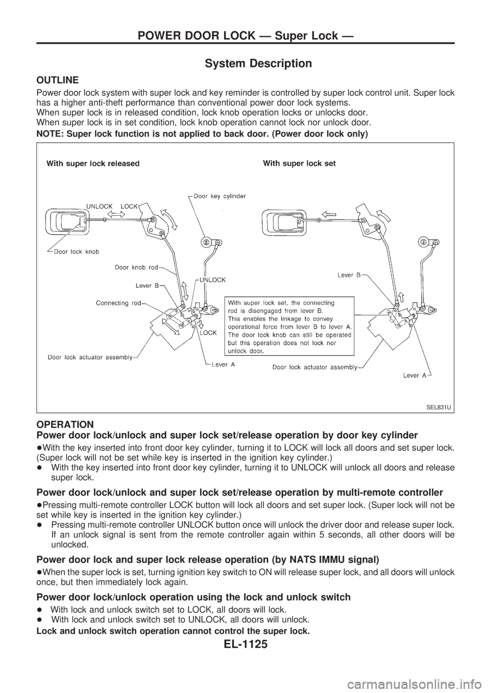
Power door lock system with super lock and key reminder is controlled by super lock control unit. Super lock
has a higher anti-theft performance than conventional power door lock systems.
When super lock is in released condition, lock knob operation locks or unlocks door.
When super lock is in set condition, lock knob operation cannot lock nor unlock door.
NOTE: Super lock function is not applied to back door. (Power door lock only)
OPERATION
Power door lock/unlock and super lock set/release operation by door key cylinder
+With the key inserted into front door key cylinder, turning it to LOCK will lock all doors and set super lock.
(Super lock will not be set while key is inserted in the ignition key cylinder.)
+With the key inserted into front door key cylinder, turning it to UNLOCK will unlock all doors and release
super lock.
Power door lock/unlock and super lock set/release operation by multi-remote controller
+Pressing multi-remote controller LOCK button will lock all doors and set super lock. (Super lock will not be
set while key is inserted in the ignition key cylinder.)
+Pressing multi-remote controller UNLOCK button once will unlock the driver door and release super lock.
If an unlock signal is sent from the remote controller again within 5 seconds, all other doors will be
unlocked.
Power door lock and super lock release operation (by NATS IMMU signal)
+When the super lock is set, turning ignition key switch to ON will release super lock, and all doors will unlock
once, but then immediately lock again.
Power door lock/unlock operation using the lock and unlock switch
+With lock and unlock switch set to LOCK, all doors will lock.
+With lock and unlock switch set to UNLOCK, all doors will unlock.
Lock and unlock switch operation cannot control the super lock.
SEL831U
POWER DOOR LOCK Ð Super Lock Ð
EL-1125
Page 636 of 1033
Key reminder system
+If the ignition key is in the ignition key cylinder and the driver door is open, setting lock knob on driver door,
key or multi-remote controller to ªLOCKº locks the door once but then immediately unlocks all doors. (Sig-
nal from unlock sensor driver side)
System initialization
+System initialization is required when battery cables are reconnected. Conduct one of the followings to
release super lock once;
Ð insert the key into ignition key cylinder and turn it to ON.
Ð LOCK/UNLOCK operation using door key cylinder or multi-remote controller.
POWER DOOR LOCK Ð Super Lock Ð
System Description (Cont'd)
EL-1126
Page 637 of 1033
Schematic
TEL261M
POWER DOOR LOCK Ð Super Lock Ð
EL-1127
Page 638 of 1033
Wiring Diagram Ð S/LOCK Ð/LHD Models
TEL262M
POWER DOOR LOCK Ð Super Lock Ð
EL-1128