Page 291 of 1033
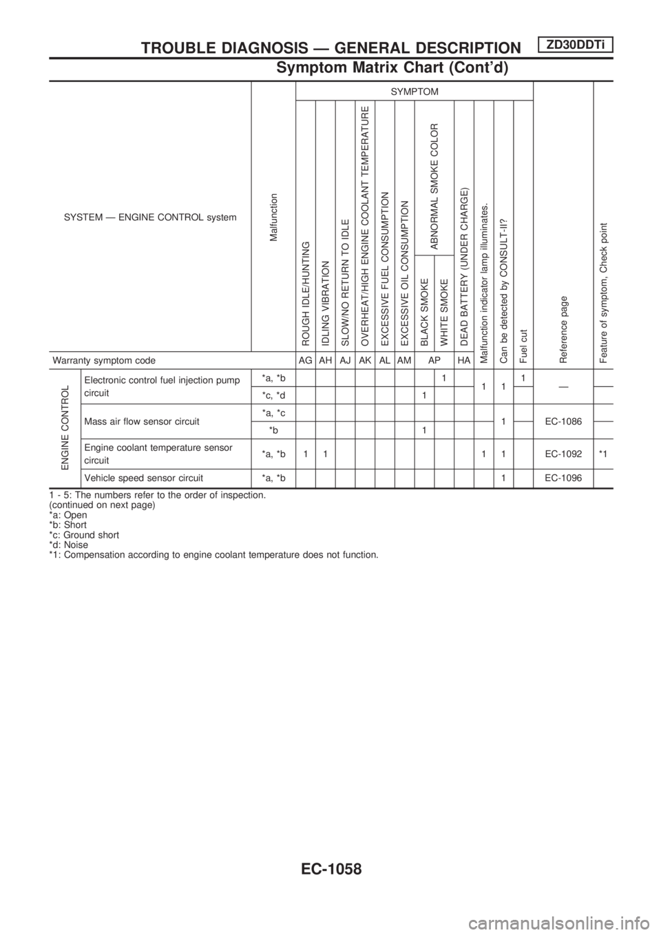
SYSTEM Ð ENGINE CONTROL system
Malfunction
SYMPTOM
Reference page
Feature of symptom, Check pointROUGH IDLE/HUNTING
IDLING VIBRATION
SLOW/NO RETURN TO IDLE
OVERHEAT/HIGH ENGINE COOLANT TEMPERATURE
EXCESSIVE FUEL CONSUMPTION
EXCESSIVE OIL CONSUMPTION
ABNORMAL SMOKE COLOR
DEAD BATTERY (UNDER CHARGE)
Malfunction indicator lamp illuminates.
Can be detected by CONSULT-II?
Fuel cutBLACK SMOKE
WHITE SMOKEWarranty symptom code AG AH AJ AK AL AM AP HA
ENGINE CONTROL
Electronic control fuel injection pump
circuit*a, *b 1
111
Ð
*c, *d 1
Mass air flow sensor circuit*a, *c
1 EC-1086
*b 1
Engine coolant temperature sensor
circuit*a, *b 1 1 1 1 EC-1092 *1
Vehicle speed sensor circuit *a, *b 1 EC-1096
1 - 5: The numbers refer to the order of inspection.
(continued on next page)
*a: Open
*b: Short
*c: Ground short
*d: Noise
*1: Compensation according to engine coolant temperature does not function.
TROUBLE DIAGNOSIS Ð GENERAL DESCRIPTIONZD30DDTi
Symptom Matrix Chart (Cont'd)
EC-1058
Page 293 of 1033
SYSTEM Ð ENGINE CONTROL system
Malfunction
SYMPTOM
Reference page
Feature of symptom, Check pointROUGH IDLE/HUNTING
IDLING VIBRATION
SLOW/NO RETURN TO IDLE
OVERHEAT/HIGH ENGINE COOLANT TEMPERATURE
EXCESSIVE FUEL CONSUMPTION
EXCESSIVE OIL CONSUMPTION
ABNORMAL SMOKE COLOR
DEAD BATTERY (UNDER CHARGE)
Malfunction indicator lamp illuminates.
Can be detected by CONSULT-II?
Fuel cutBLACK SMOKE
WHITE SMOKEWarranty symptom code AG AH AJ AK AL AM AP HA
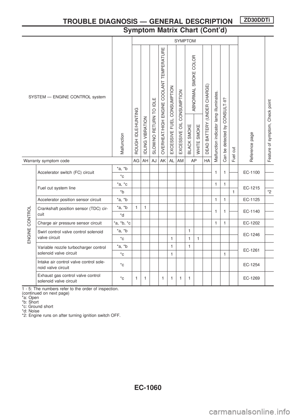
ENGINE CONTROL
Accelerator switch (FC) circuit*a, *b
1 1 EC-1100
*c
Fuel cut system line*a, *c 1 1
EC-1215
*b 1 *2
Accelerator position sensor circuit *a, *b 1 1 EC-1125
Crankshaft position sensor (TDC) cir-
cuit*a, *b 1 1
1 1 EC-1140
*d
Charge air pressure sensor circuit *a, *b, *c 1 1 EC-1202
Swirl control valve control solenoid
valve circuit*a, *b 1
EC-1246
*c 1 1 1
Variable nozzle turbocharger control
solenoid valve circuit*a, *b 1 1
EC-1261
*c 1 1
Intake air control valve control sole-
noid valve circuit*c EC-1254
Exhaust gas control valve control
solenoid valve circuit*c 11 1111EC-1269
1 - 5: The numbers refer to the order of inspection.
(continued on next page)
*a: Open
*b: Short
*c: Ground short
*d: Noise
*2: Engine runs on after turning ignition switch OFF.
TROUBLE DIAGNOSIS Ð GENERAL DESCRIPTIONZD30DDTi
Symptom Matrix Chart (Cont'd)
EC-1060
Page 295 of 1033
SYSTEM Ð ENGINE CONTROL system
Malfunction
SYMPTOM
Reference page
Feature of symptom, Check pointROUGH IDLE/HUNTING
IDLING VIBRATION
SLOW/NO RETURN TO IDLE
OVERHEAT/HIGH ENGINE COOLANT TEMPERATURE
EXCESSIVE FUEL CONSUMPTION
EXCESSIVE OIL CONSUMPTION
ABNORMAL SMOKE COLOR
DEAD BATTERY (UNDER CHARGE)
Malfunction indicator lamp illuminates.
Can be detected by CONSULT-II?
Fuel cutBLACK SMOKE
WHITE SMOKEWarranty symptom code AG AH AJ AK AL AM AP HA
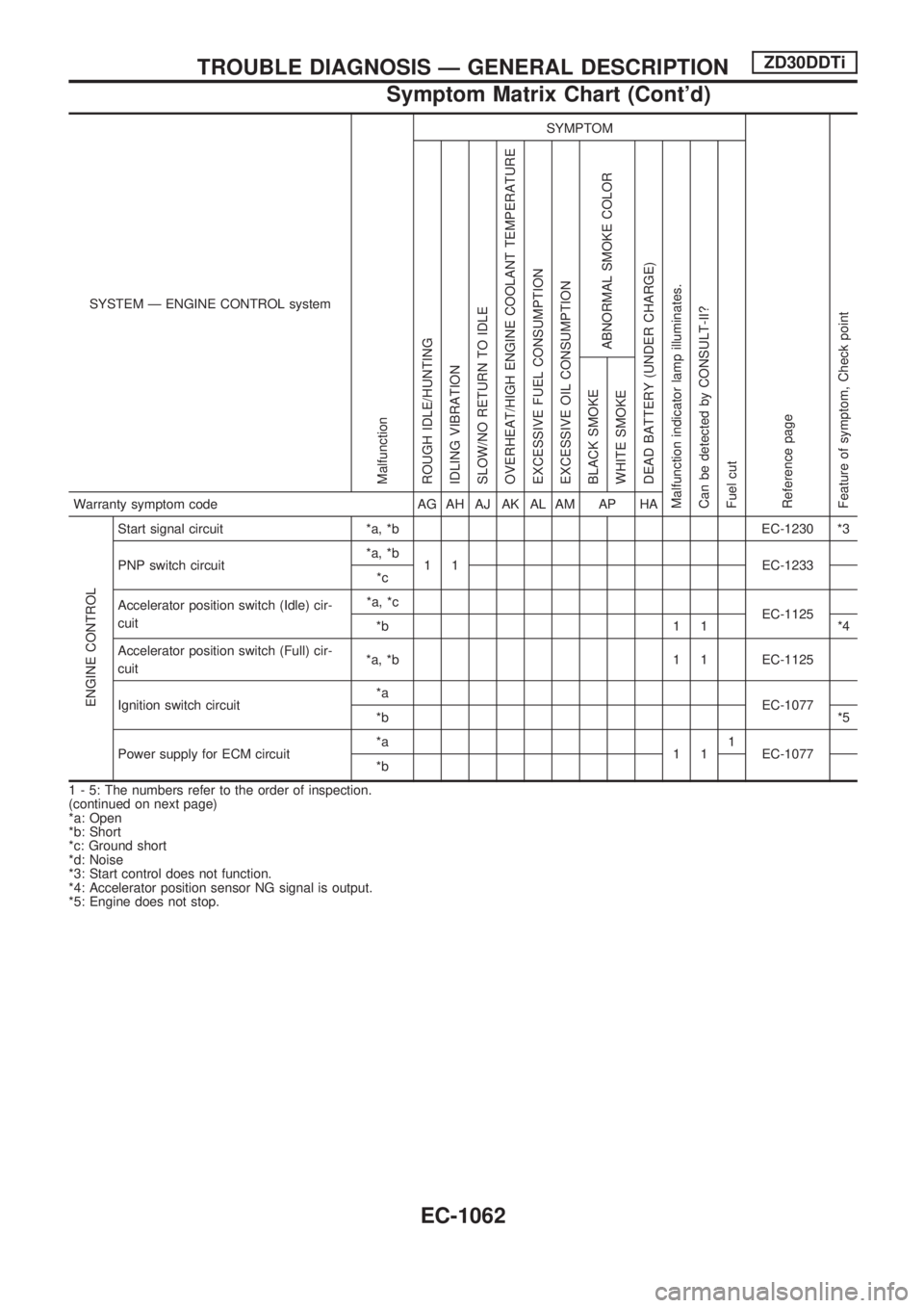
ENGINE CONTROL
Start signal circuit *a, *b EC-1230 *3
PNP switch circuit*a, *b
1 1 EC-1233
*c
Accelerator position switch (Idle) cir-
cuit*a, *c
EC-1125
*b 1 1 *4
Accelerator position switch (Full) cir-
cuit*a, *b 1 1 EC-1125
Ignition switch circuit*a
EC-1077
*b*5
Power supply for ECM circuit*a
111
EC-1077
*b
1 - 5: The numbers refer to the order of inspection.
(continued on next page)
*a: Open
*b: Short
*c: Ground short
*d: Noise
*3: Start control does not function.
*4: Accelerator position sensor NG signal is output.
*5: Engine does not stop.
TROUBLE DIAGNOSIS Ð GENERAL DESCRIPTIONZD30DDTi
Symptom Matrix Chart (Cont'd)
EC-1062
Page 297 of 1033
SYSTEM Ð ENGINE CONTROL system
Malfunction
SYMPTOM
Reference page
Feature of symptom, Check pointROUGH IDLE/HUNTING
IDLING VIBRATION
SLOW/NO RETURN TO IDLE
OVERHEAT/HIGH ENGINE COOLANT TEMPERATURE
EXCESSIVE FUEL CONSUMPTION
EXCESSIVE OIL CONSUMPTION
ABNORMAL SMOKE COLOR
DEAD BATTERY (UNDER CHARGE)
Malfunction indicator lamp illuminates.
Can be detected by CONSULT-II?
Fuel cutBLACK SMOKE
WHITE SMOKEWarranty symptom code AG AH AJ AK AL AM AP HA
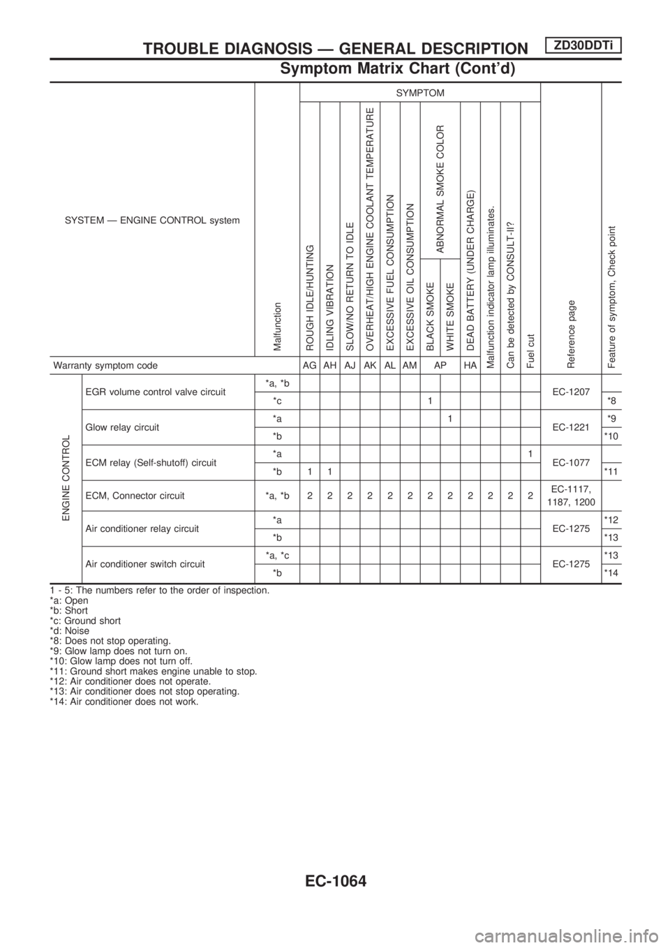
ENGINE CONTROL
EGR volume control valve circuit*a, *b
EC-1207
*c 1 *8
Glow relay circuit*a 1
EC-1221*9
*b*10
ECM relay (Self-shutoff) circuit*a 1
EC-1077
*b 1 1 *11
ECM, Connector circuit *a, *b222222222222EC-1117,
1187, 1200
Air conditioner relay circuit*a
EC-1275*12
*b*13
Air conditioner switch circuit*a, *c
EC-1275*13
*b*14
1 - 5: The numbers refer to the order of inspection.
*a: Open
*b: Short
*c: Ground short
*d: Noise
*8: Does not stop operating.
*9: Glow lamp does not turn on.
*10: Glow lamp does not turn off.
*11: Ground short makes engine unable to stop.
*12: Air conditioner does not operate.
*13: Air conditioner does not stop operating.
*14: Air conditioner does not work.
TROUBLE DIAGNOSIS Ð GENERAL DESCRIPTIONZD30DDTi
Symptom Matrix Chart (Cont'd)
EC-1064
Page 299 of 1033
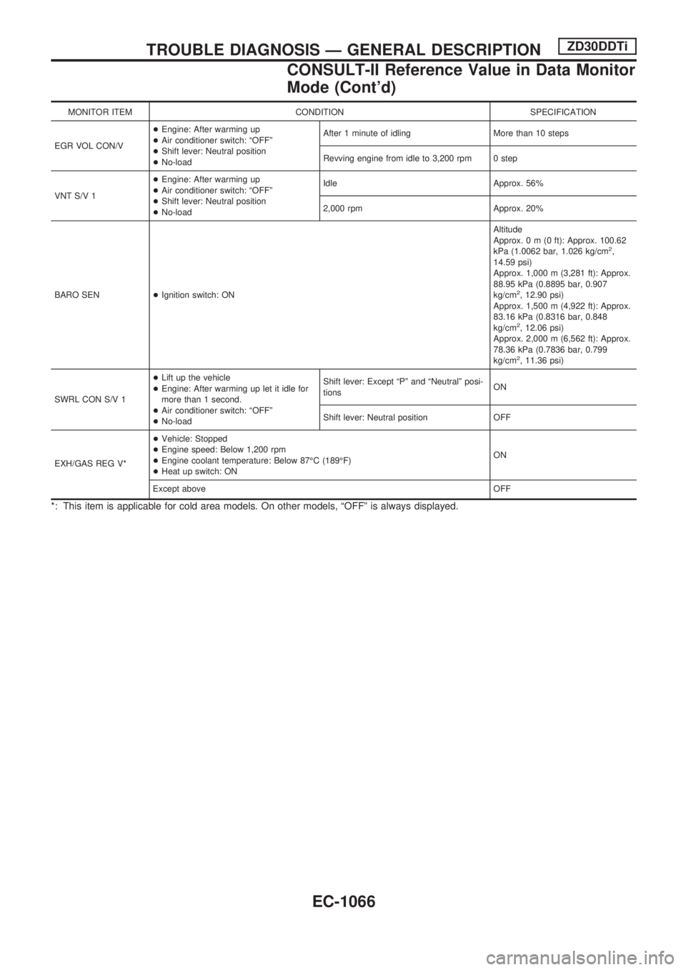
MONITOR ITEM CONDITION SPECIFICATION
EGR VOL CON/V+Engine: After warming up
+Air conditioner switch: ªOFFº
+Shift lever: Neutral position
+No-loadAfter 1 minute of idling More than 10 steps
Revving engine from idle to 3,200 rpm 0 step
VNT S/V 1+Engine: After warming up
+Air conditioner switch: ªOFFº
+Shift lever: Neutral position
+No-loadIdle Approx. 56%
2,000 rpm Approx. 20%
BARO SEN+Ignition switch: ONAltitude
Approx.0m(0ft): Approx. 100.62
kPa (1.0062 bar, 1.026 kg/cm
2,
14.59 psi)
Approx. 1,000 m (3,281 ft): Approx.
88.95 kPa (0.8895 bar, 0.907
kg/cm
2, 12.90 psi)
Approx. 1,500 m (4,922 ft): Approx.
83.16 kPa (0.8316 bar, 0.848
kg/cm
2, 12.06 psi)
Approx. 2,000 m (6,562 ft): Approx.
78.36 kPa (0.7836 bar, 0.799
kg/cm
2, 11.36 psi)
SWRL CON S/V 1+Lift up the vehicle
+Engine: After warming up let it idle for
more than 1 second.
+Air conditioner switch: ªOFFº
+No-loadShift lever: Except ªPº and ªNeutralº posi-
tionsON
Shift lever: Neutral position OFF
EXH/GAS REG V*+Vehicle: Stopped
+Engine speed: Below 1,200 rpm
+Engine coolant temperature: Below 87ÉC (189ÉF)
+Heat up switch: ONON
Except aboveOFF
*: This item is applicable for cold area models. On other models, ªOFFº is always displayed.
TROUBLE DIAGNOSIS Ð GENERAL DESCRIPTIONZD30DDTi
CONSULT-II Reference Value in Data Monitor
Mode (Cont'd)
EC-1066
Page 303 of 1033
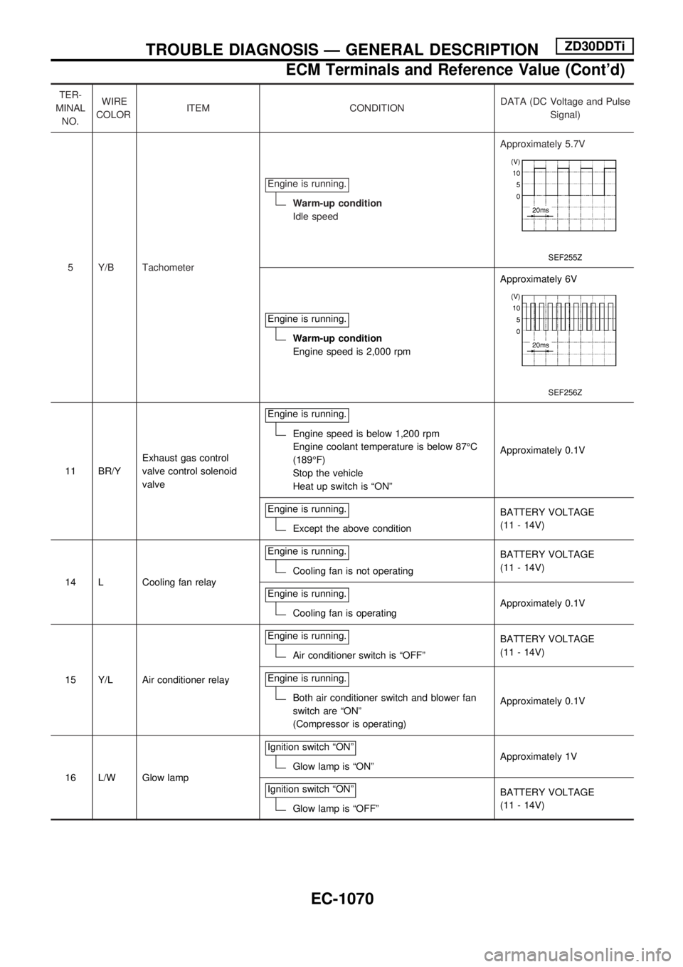
TER-
MINAL
NO.WIRE
COLORITEM CONDITIONDATA (DC Voltage and Pulse
Signal)
5 Y/B TachometerEngine is running.
Warm-up condition
Idle speedApproximately 5.7V
SEF255Z
Engine is running.
Warm-up condition
Engine speed is 2,000 rpmApproximately 6V
SEF256Z
11 BR/YExhaust gas control
valve control solenoid
valveEngine is running.
Engine speed is below 1,200 rpm
Engine coolant temperature is below 87ÉC
(189ÉF)
Stop the vehicle
Heat up switch is ªONºApproximately 0.1V
Engine is running.
Except the above conditionBATTERY VOLTAGE
(11 - 14V)
14 L Cooling fan relayEngine is running.
Cooling fan is not operatingBATTERY VOLTAGE
(11 - 14V)
Engine is running.
Cooling fan is operatingApproximately 0.1V
15 Y/L Air conditioner relayEngine is running.
Air conditioner switch is ªOFFºBATTERY VOLTAGE
(11 - 14V)
Engine is running.
Both air conditioner switch and blower fan
switch are ªONº
(Compressor is operating)Approximately 0.1V
16 L/W Glow lampIgnition switch ªONº
Glow lamp is ªONºApproximately 1V
Ignition switch ªONº
Glow lamp is ªOFFºBATTERY VOLTAGE
(11 - 14V)
TROUBLE DIAGNOSIS Ð GENERAL DESCRIPTIONZD30DDTi
ECM Terminals and Reference Value (Cont'd)
EC-1070
Page 304 of 1033
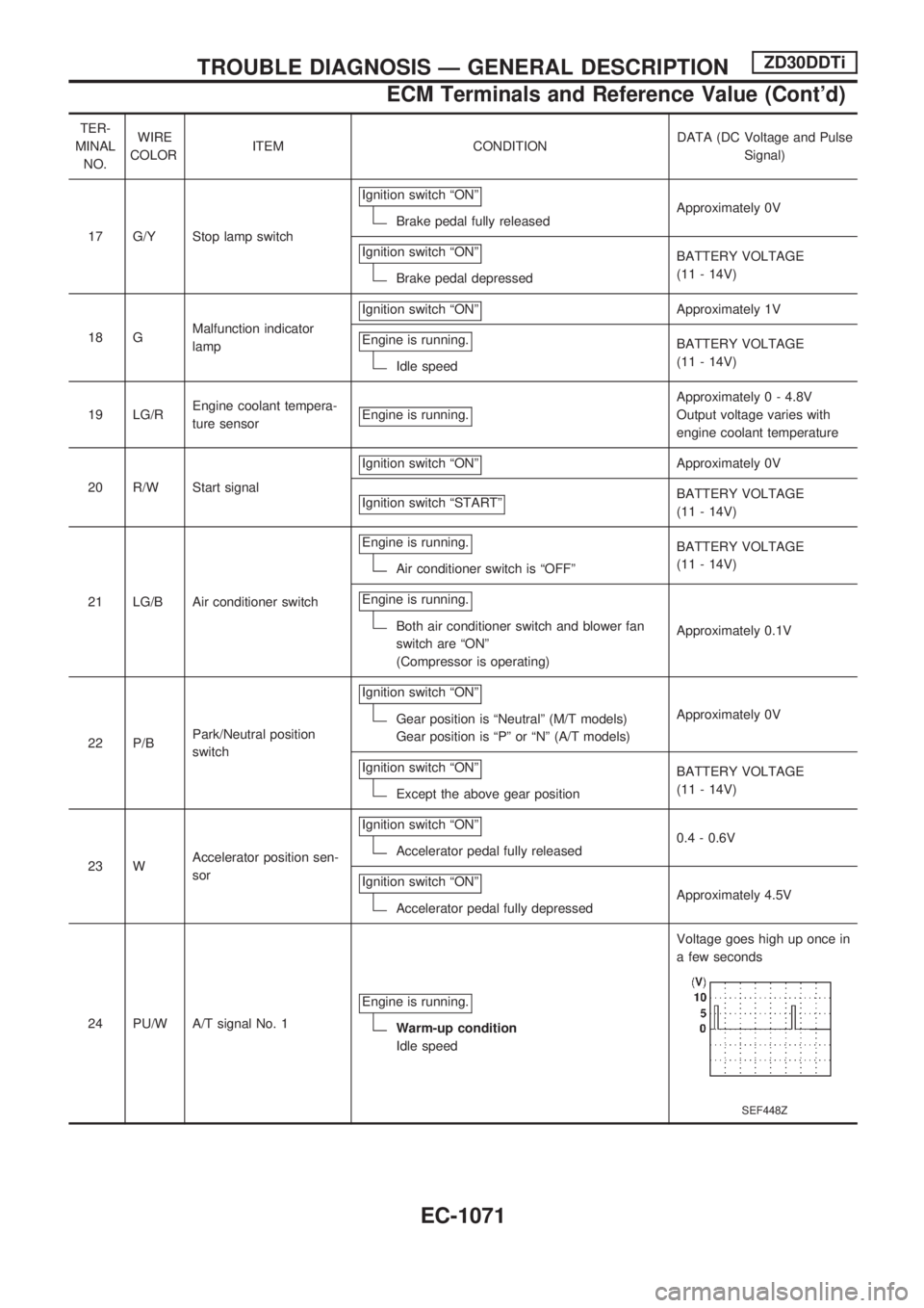
TER-
MINAL
NO.WIRE
COLORITEM CONDITIONDATA (DC Voltage and Pulse
Signal)
17 G/Y Stop lamp switchIgnition switch ªONº
Brake pedal fully releasedApproximately 0V
Ignition switch ªONº
Brake pedal depressedBATTERY VOLTAGE
(11 - 14V)
18 GMalfunction indicator
lampIgnition switch ªONº
Approximately 1V
Engine is running.
Idle speedBATTERY VOLTAGE
(11 - 14V)
19 LG/REngine coolant tempera-
ture sensorEngine is running.
Approximately 0 - 4.8V
Output voltage varies with
engine coolant temperature
20 R/W Start signalIgnition switch ªONº
Approximately 0V
Ignition switch ªSTARTº
BATTERY VOLTAGE
(11 - 14V)
21 LG/B Air conditioner switchEngine is running.
Air conditioner switch is ªOFFºBATTERY VOLTAGE
(11 - 14V)
Engine is running.
Both air conditioner switch and blower fan
switch are ªONº
(Compressor is operating)Approximately 0.1V
22 P/BPark/Neutral position
switchIgnition switch ªONº
Gear position is ªNeutralº (M/T models)
Gear position is ªPº or ªNº (A/T models)Approximately 0V
Ignition switch ªONº
Except the above gear positionBATTERY VOLTAGE
(11 - 14V)
23 WAccelerator position sen-
sorIgnition switch ªONº
Accelerator pedal fully released0.4 - 0.6V
Ignition switch ªONº
Accelerator pedal fully depressedApproximately 4.5V
24 PU/W A/T signal No. 1Engine is running.
Warm-up condition
Idle speedVoltage goes high up once in
a few seconds
SEF448Z
TROUBLE DIAGNOSIS Ð GENERAL DESCRIPTIONZD30DDTi
ECM Terminals and Reference Value (Cont'd)
EC-1071
Page 325 of 1033
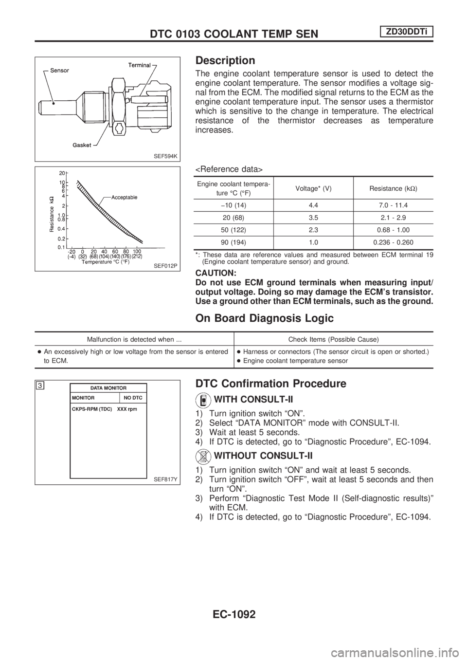
Description
The engine coolant temperature sensor is used to detect the
engine coolant temperature. The sensor modifies a voltage sig-
nal from the ECM. The modified signal returns to the ECM as the
engine coolant temperature input. The sensor uses a thermistor
which is sensitive to the change in temperature. The electrical
resistance of the thermistor decreases as temperature
increases.
Engine coolant tempera-
ture ÉC (ÉF)Voltage* (V) Resistance (kW)
þ10 (14) 4.4 7.0 - 11.4
20 (68) 3.5 2.1 - 2.9
50 (122) 2.3 0.68 - 1.00
90 (194) 1.0 0.236 - 0.260
*: These data are reference values and measured between ECM terminal 19
(Engine coolant temperature sensor) and ground.
CAUTION:
Do not use ECM ground terminals when measuring input/
output voltage. Doing so may damage the ECM's transistor.
Use a ground other than ECM terminals, such as the ground.
On Board Diagnosis Logic
Malfunction is detected when ... Check Items (Possible Cause)
+An excessively high or low voltage from the sensor is entered
to ECM.+Harness or connectors (The sensor circuit is open or shorted.)
+Engine coolant temperature sensor
DTC Confirmation Procedure
WITH CONSULT-II
1) Turn ignition switch ªONº.
2) Select ªDATA MONITORº mode with CONSULT-II.
3) Wait at least 5 seconds.
4) If DTC is detected, go to ªDiagnostic Procedureº, EC-1094.
WITHOUT CONSULT-II
1) Turn ignition switch ªONº and wait at least 5 seconds.
2) Turn ignition switch ªOFFº, wait at least 5 seconds and then
turn ªONº.
3) Perform ªDiagnostic Test Mode II (Self-diagnostic results)º
with ECM.
4) If DTC is detected, go to ªDiagnostic Procedureº, EC-1094.
SEF594K
SEF012P
SEF817Y
DTC 0103 COOLANT TEMP SENZD30DDTi
EC-1092