2000 MITSUBISHI MONTERO ECU
[x] Cancel search: ECUPage 280 of 1839
GDI -Troubleshooting
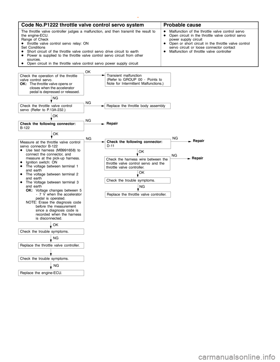
Code No.P1222 throttle valve control servo systemProbable cause
The throttle valve controller judges a malfunction, and then transmit the result to
the engine-ECU.
Range of Check
Dthrottle valve control servo relay: ON
Set Conditions
DShort circuit of the throttle valve control servo drive circuit to earth
DPower is supplied to the throttle valve control servo circuit from other
sources.
DOpen circuit in the throttle valve control servo power supply circuitDMalfunction of the throttle valve control servo
DOpen circuit in the throttle valve control servo
power supply circuit
DOpen or short circuit in the throttle valve control
servo circuit or loose connector contact
DMalfunction of throttle valve controller
OKTransient malfunction
(Refer to GROUP 00 - Points to
Note for Intermittent Malfunctions.)
OK
Check the following connector:
B-122NG
Repair
OK
Measure at the throttle valve control
servo connector B-122
DUse test harness (MB991658) to
connect the connector, and
measure at the pick-up harness.
DIgnition switch: ON
DThe voltage between terminal 1
and earth
DThe voltage between terminal 2
and earth
DThe Voltage between terminal 3
and earth
OK:
Voltage changes between 5
- 7 V when the accelerator
pedal is operated.
NOTE: Erase the diagnosis code
before the measurement
since a diagnosis code is
recorded when the harness
is disconnected.NGCheck the following connector:
D-11NG
Repair
OK
Check the trouble symptoms.
OK
Check the trouble symptoms.
OK
Check the harness wire between the
throttle valve control servo and the
throttle valve controller.NG
Repair
NG
Check the throttle valve control
servo (Refer to P.13A-232.)NGReplace the throttle body assembly
NG
Replace the throttle valve controller.
NG
Replace the throttle valve controller.
Check the trouble symptoms.
NG
Replace the engine-ECU.
Check the operation of the throttle
valve control servo.
OK:
The throttle valve opens or
closes when the accelerator
pedal is depressed or released.
www.WorkshopManuals.co.uk
Purchased from www.WorkshopManuals.co.uk
Page 281 of 1839
GDI -Troubleshooting
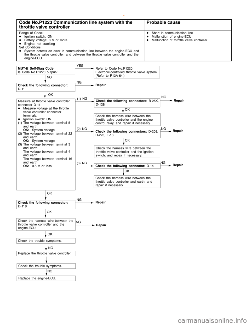
Code No.P1223 Communication line system with the
throttle valve controllerProbable cause
Range of Check
DIgnition switch: ON
DBattery voltage: 8 V or more.
DEngine: not cranking
Set Conditions
DSystem detects an error in communicationline between the engine-ECU and
the throttle valve controller, and between the throttle valve controller and the
engine-ECU.DShort in communicationline
DMalfunction of engine-ECU
DMalfunction of throttle valve controller
MUT-
IISelf-Diag Code
Is Code No.P1220 output?YESRefer to Code No.P1220,
Electronic-controlled throttle valve system
(Refer to P13A-64.)
NO
NG
Repair
OK
Measure at throttle valve controller
connector D-11.
DMeasure voltage at the throttle
valve controller connector
terminals.
DIgnition switch: ON
(1) The voltage between terminal 5
and earth
OK:
System voltage
(2) The voltage between terminal 22
and earth
OK:
System voltage
(3) The voltage between terminal 3
and earth
The voltage between terminal 4
and earth
The voltage between terminal 16
and earth
OK:
0.5 V or less(1) NGCheck the following connectors:
B-25X,
D-128NG
Repair
Check the trouble symptoms.OK
Check the harness wire between the
throttle valve controller and theengine
control relay, and repair if necessary.
OK
Check the trouble symptoms.
NG
Replace the engine-ECU.
(2) NGCheck the following connectors:
D-208,
D-223, E-13NG
Repair
OK
Check the harness wire between the
throttle valve controller and the ignition
switch, and repair if necessary.
(3) NGCheck the following connector:
D-14NG
Repair
OK
Check the harness wire between the
throttle valve controller and earth, and
repair if necessary.
OK
Check the following connector:
D-118NG
Repair
OK
Check the harness wire between the
throttle valve controller and the
engine-ECU.NG
Repair
NG
Replace the throttle valve controller.
Check the following connector:
D-11
www.WorkshopManuals.co.uk
Purchased from www.WorkshopManuals.co.uk
Page 282 of 1839
GDI -Troubleshooting
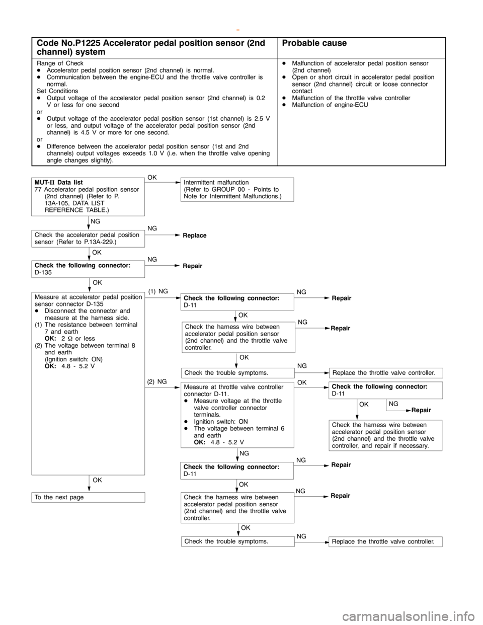
Code No.P1225 Accelerator pedal position sensor (2nd
channel) systemProbable cause
Range of Check
DAcceleratorpedal positionsensor (2nd channel) is normal.
DCommunication between the engine-ECU and the throttle valve controller is
normal.
Set Conditions
DOutput voltage of the accelerator pedal positionsensor (2nd channel) is 0.2
V or less for one second
or
DOutput voltage of the accelerator pedal positionsensor (1st channel) is 2.5 V
or less, and output voltage of the acceleratorpedal positionsensor (2nd
channel) is 4.5 V or more for one second.
or
DDifference between the accelerator pedal positionsensor (1st and 2nd
channels) output voltages exceeds 1.0 V (i.e. when the throttle valveopening
anglechanges slightly).DMalfunction of accelerator pedal positionsensor
(2nd channel)
DOpen or short circuit in acceleratorpedal position
sensor (2nd channel) circuit or loose connector
contact
DMalfunction of the throttle valve controller
DMalfunction of engine-ECU
OKIntermittent malfunction
(Refer to GROUP 00 - Points to
Note for Intermittent Malfunctions.)
NG
Check the acceleratorpedal position
sensor (Refer to P.13A-229.)NG
Replace
OK
Measure at accelerator pedal position
sensor connector D-135
DDisconnect the connector and
measure at the harness side.
(1) The resistance between terminal
7 and earth
OK:
2Wor less
(2) The voltage between terminal 8
and earth
(Ignition switch: ON)
OK:
4.8 - 5.2 V(1) NGCheck the following connector:
D-11NG
Repair
OK
Check the following connector:
D-135NG
Repair
Check the harness wire between
accelerator pedal positionsensor
(2nd channel) and the throttle valve
controller.NG
Repair
OK
Check the trouble symptoms.NGReplace the throttle valve controller.
(2) NGMeasure at throttle valve controller
connector D-11.
DMeasure voltage at the throttle
valve controller connector
terminals.
DIgnition switch: ON
DThe voltage between terminal 6
and earth
OK:
4.8 - 5.2 VOK
OK
Check the harness wire between
accelerator pedal positionsensor
(2nd channel) and the throttle valve
controller, and repair if necessary.NG
Repair
NG
Check the following connector:
D-11NG
Repair
OK
Check the harness wire between
accelerator pedal positionsensor
(2nd channel) and the throttle valve
controller.NG
Repair
OK
To the nextpage
OK
Check the trouble symptoms.NGReplace the throttle valve controller. OK
MUT-
IIData list
77 Acceleratorpedal positionsensor
(2nd channel) (Refer to P.
13A-105, DATA LIST
REFERENCE TABLE.)
Check the following connector:
D-11
www.WorkshopManuals.co.uk
Purchased from www.WorkshopManuals.co.uk
Page 284 of 1839
GDI -Troubleshooting
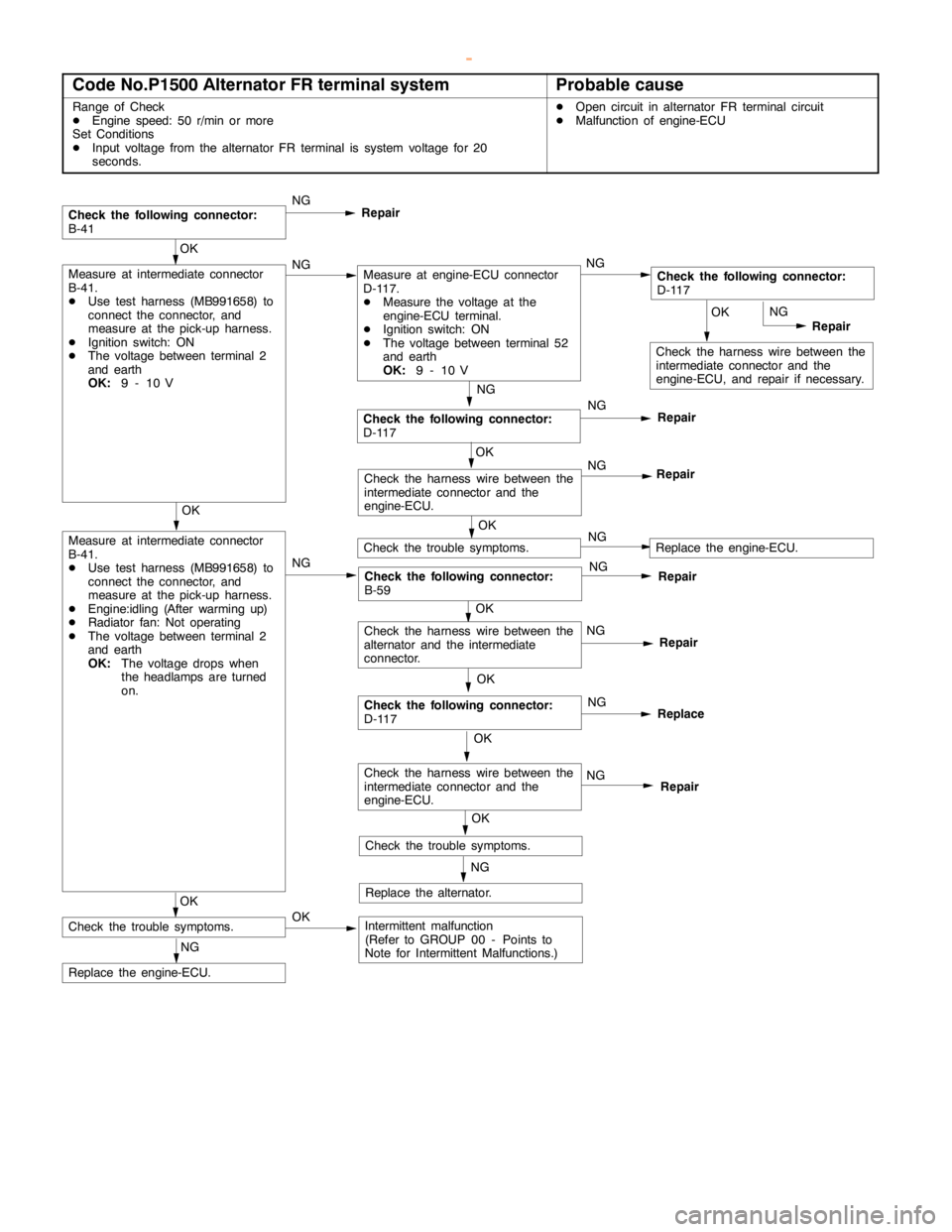
Code No.P1500 Alternator FR terminal systemProbable cause
Range of Check
DEngine speed: 50 r/min or more
Set Conditions
DInput voltage from the alternator FR terminal is system voltage for 20
seconds.DOpen circuit in alternator FR terminal circuit
DMalfunction of engine-ECU
OK
Check the harness wire between the
intermediate connector and the
engine-ECU, and repair if necessary.NG
Repair
NG
Check the following connector:
D-117NG
Repair
Check the following connector:
B-41NG
Repair
OK
Measure at intermediate connector
B-41.
DUse test harness (MB991658) to
connect the connector, and
measure at the pick-up harness.
DEngine:idling (After warming up)
DRadiator fan: Not operating
DThe voltage between terminal 2
and earth
OK:
The voltage drops when
the headlamps are turned
on.NG
Check the following connector:
B-59NG
Repair
OK
Check the trouble symptoms.
NG
Replace the engine-ECU.
OK
Check the harness wire between the
intermediate connector and the
engine-ECU.NG
Repair
OK
Measure at intermediate connector
B-41.
DUse test harness (MB991658) to
connect the connector, and
measure at the pick-up harness.
DIgnition switch: ON
DThe voltage between terminal 2
and earth
OK:
9 - 10 VNGMeasure at engine-ECU connector
D-117.
DMeasure the voltage at the
engine-ECU terminal.
DIgnition switch: ON
DThe voltage between terminal 52
and earth
OK:
9 - 10 VNGCheck the following connector:
D-117
OK
NG
Repair
OK
Check the following connector:
D-117NG
Replace
OK
Check the trouble symptoms.NGReplace the engine-ECU.
OK
Check the harness wire between the
intermediate connector and the
engine-ECU.NG
Repair
NG
Replace the alternator.OK
Check the trouble symptoms.OKIntermittent malfunction
(Refer to GROUP 00 - Points to
Note for Intermittent Malfunctions.)
Check the harness wire between the
alternator and the intermediate
connector.
www.WorkshopManuals.co.uk
Purchased from www.WorkshopManuals.co.uk
Page 285 of 1839
GDI -Troubleshooting
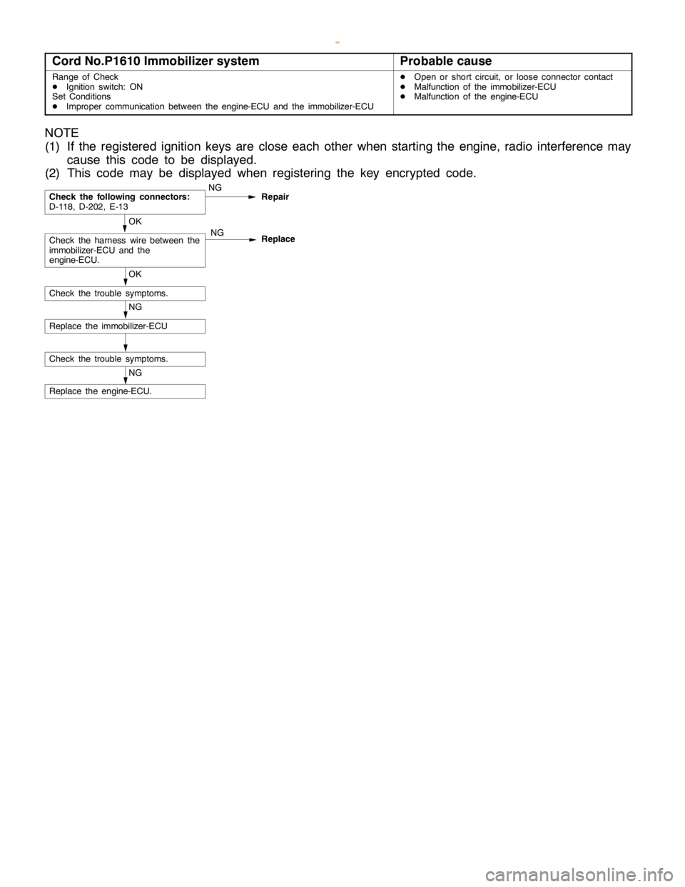
Cord No.P1610 Immobilizer systemProbable cause
Range of Check
DIgnition switch: ON
Set Conditions
DImproper communication between the engine-ECU and the immobilizer-ECUDOpen or short circuit, or loose connector contact
DMalfunction of the immobilizer-ECU
DMalfunction of the engine-ECU
NOTE
(1) If the registered ignition keys are close each other when starting the engine, radio interference may
cause this code to be displayed.
(2) This code may be displayed when registering the key encrypted code.
NG
Replace the engine-ECU.
Check the trouble symptoms.
NG
Replace the immobilizer-ECU
OK
Check the trouble symptoms.
OK
Check the harness wire between the
immobilizer-ECU and the
engine-ECU.NG
Replace
Check the following connectors:
D-118, D-202, E-13NG
Repair
www.WorkshopManuals.co.uk
Purchased from www.WorkshopManuals.co.uk
Page 286 of 1839

GDI -Troubleshooting
INSPECTION CHART FOR TROUBLE SYMPTOMS
Trouble symptomInspection
procedure
No.Reference page
CommunicationCommunication with all systems is not possible.113A-74
with MUT-IIis
impossible.
Communication with engine-ECU only is not possible.213A-75
Engine warning
lamp andThe engine warning lamp does not illuminate right after the
ignition switch is turned to the ON position.313A-76
related parts
The engine warning lamp remains illuminating and never goes
out.413A-76
StartingNo initial combustion (starting impossible)513A-77
Initial combustion but no complete combustion
(starting impossible)613A-79
Long time to start (improper starting)
Idling stabilityUnstable idling (Rough idling, hunting)713A-81
(Improper idling)
Idling speed is high. (Improper idling speed)813A-83
Idling speed is low. (Improper idling speed)
Idling stabilityWhen the engine is cold, it stalls at idling. (Die out)913A-84
(Engine stalls)
When the engine is hot, it stalls at idling. (Die out)1013A-85
The engine stalls when starting the car. (Pass out)1113A-87
The engine stalls when decelerating.1213A-88
DrivingHesitation, sag or stumble1313A-89
Poor acceleration
Surge
The feeling of impact or vibration when accelerating1413A-90
The feeling of impact or vibration when decelerating1513A-91
Knocking1613A-91
Dieseling1713A-91
Too high CO and HC concentration when idling1813A-92
Low alternator output voltage (approx. 12.3 V)1913A-94
Engine idle speed is incorrect while the A/C is on.2013A-94
A/C condenser fan is inoperative2113A-95
Clutch switch system malfunction2213A-96
GDI ECO indi-GDI ECO indicator lamp does not illuminate.2313A-96
cator lamp sys-
tem
GDI ECO indicator lamp remains illuminated and does not go off.2413A-97
www.WorkshopManuals.co.uk
Purchased from www.WorkshopManuals.co.uk
Page 289 of 1839
GDI -Troubleshooting
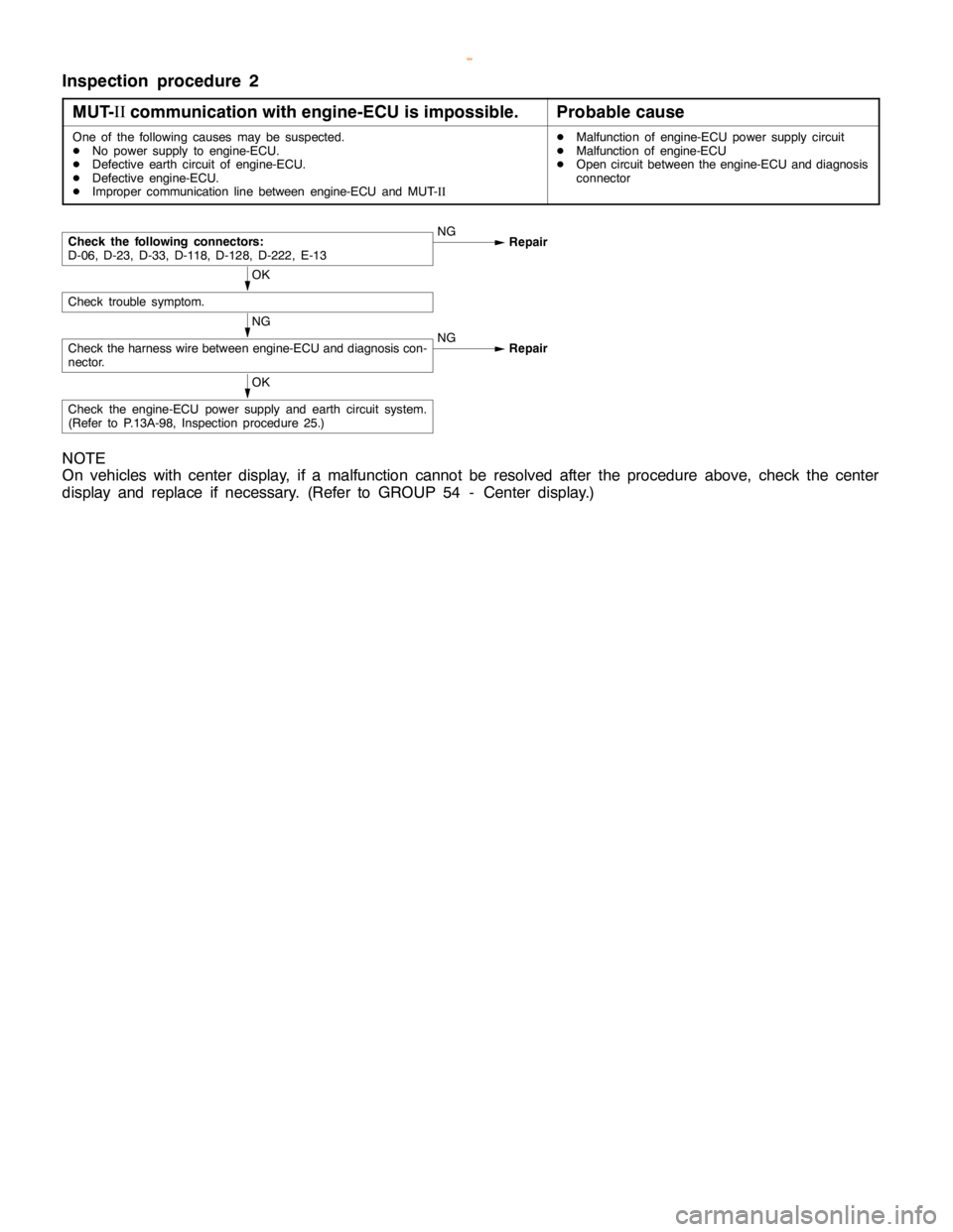
Inspection procedure 2
MUT-II
communication with engine-ECU is impossible.
Probable cause
One of the following causes may be suspected.
DNo power supply to engine-ECU.
DDefective earth circuit of engine-ECU.
DDefective engine-ECU.
DImproper communication line between engine-ECU and MUT-IIDMalfunction of engine-ECU power supply circuit
DMalfunction of engine-ECU
DOpen circuit between the engine-ECU and diagnosis
connector
NG
Check the harness wire between engine-ECU and diagnosis con-
nector.NG
Repair
OK
Check trouble symptom.
Check the following connectors:
D-06, D-23, D-33, D-118, D-128, D-222, E-13NG
Repair
OK
Check the engine-ECU power supply and earth circuit system.
(Refer to P.13A-98, Inspection procedure 25.)
NOTE
On vehicles with center display, if a malfunction cannot be resolved after the procedure above, check the center
display and replace if necessary. (Refer to GROUP 54 - Center display.)
www.WorkshopManuals.co.uk
Purchased from www.WorkshopManuals.co.uk
Page 290 of 1839
GDI -Troubleshooting
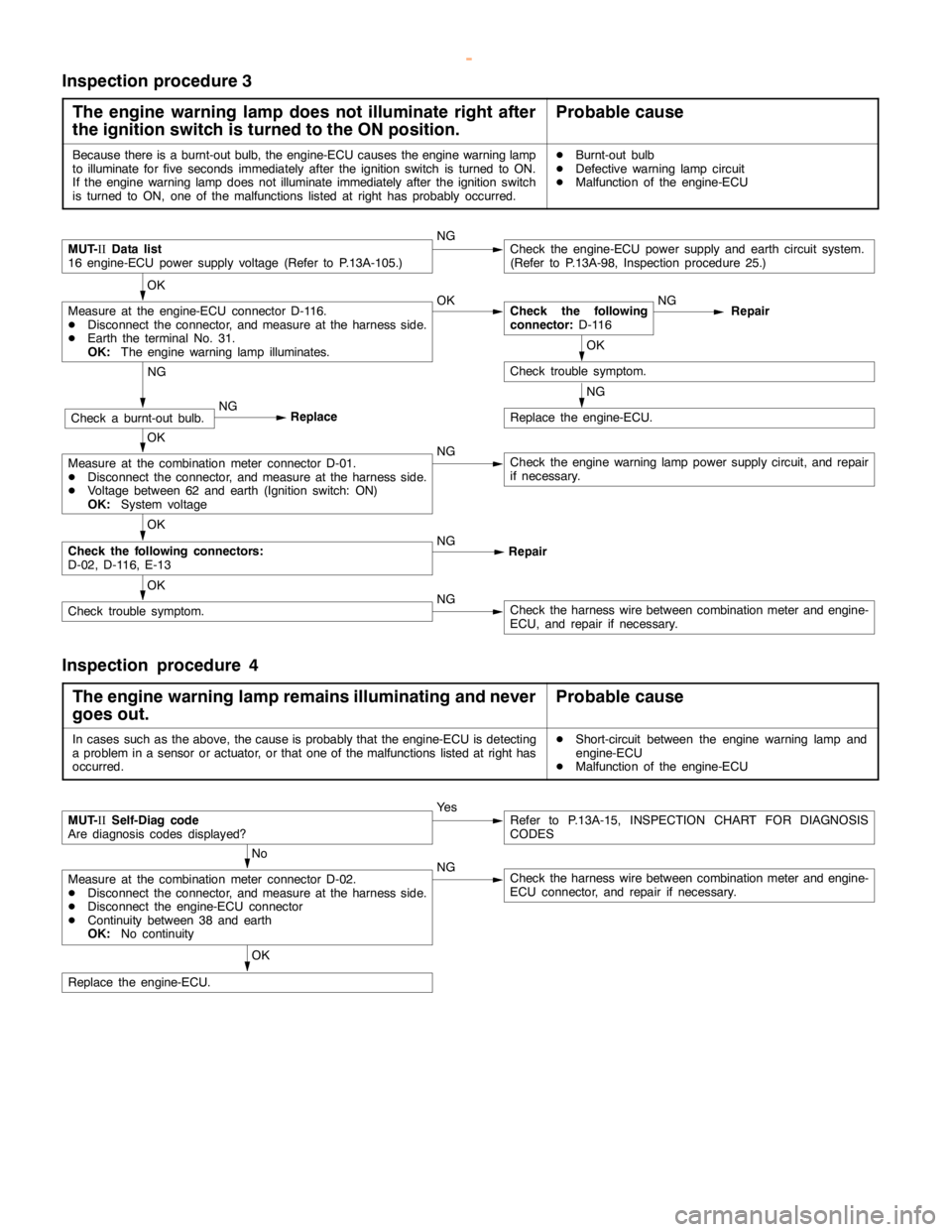
Inspection procedure 3
The engine warning lamp does not illuminate right after
the ignition switch is turned to the ON position.
Probable cause
Because there is a burnt-out bulb, the engine-ECU causes theengine warning lamp
to illuminate forfive seconds immediately after the ignition switch is turned to ON.
If the engine warning lampdoes notilluminate immediately after the ignitionswitch
is turned to ON, one of the malfunctions listed at right has probably occurred.DBurnt-out bulb
DDefective warninglampcircuit
DMalfunction of the engine-ECU
MUT-
IIData list
16 engine-ECU power supply voltage (Refer to P.13A-105.)NGCheck the engine-ECU power supply and earth circuit system.
(Refer to P.13A-98, Inspection procedure 25.)
OK
Measure at the engine-ECU connector D-116.
DDisconnect the connector, and measure at the harness side.
DEarth the terminal No. 31.
OK:
The engine warning lamp illuminates.OKCheck the following
connector:
D-116NG
Repair
OK
Check trouble symptom.
NG
Replace the engine-ECU.
NG
Check a burnt-out bulb.NG
Replace
OK
Measure at the combination meter connector D-01.
DDisconnect the connector, and measure at the harness side.
DVoltage between 62 and earth (Ignition switch: ON)
OK:
System voltageNGCheck theengine warning lamppower supply circuit, and repair
if necessary.
OK
Check the following connectors:
D-02, D-116, E-13NG
Repair
OK
Check trouble symptom.NGCheck the harness wire between combination meter and engine-
ECU, and repair if necessary.
Inspection procedure 4
The engine warning lamp remains illuminating and never
goes out.
Probable cause
In cases such as the above, the cause is probably that the engine-ECU is detecting
a problem in a sensor or actuator, or that one of the malfunctions listed at right has
occurred.DShort-circuit between the engine warning lamp and
engine-ECU
DMalfunction of the engine-ECU
MUT-
IISelf-Diag code
Are diagnosis codes displayed?Ye sRefer to P.13A-15, INSPECTION CHART FOR DIAGNOSIS
CODES
No
Measure at the combination meter connector D-02.
DDisconnect the connector, and measure at the harness side.
DDisconnect the engine-ECU connector
DContinuity between 38 and earth
OK:
No continuityNGCheck the harness wire between combination meter and engine-
ECU connector, and repair if necessary.
OK
Replace the engine-ECU.
www.WorkshopManuals.co.uk
Purchased from www.WorkshopManuals.co.uk