2000 MITSUBISHI MONTERO check engine
[x] Cancel search: check enginePage 1283 of 1839
ABS <4WD> -Troubleshooting35B-20
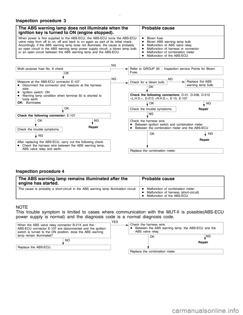
Inspection procedure 3
The ABS warning lamp does not illuminate when the
ignition key is turned to ON (engine stopped).
Probable cause
When power is first supplied to the ABS-ECU, the ABS-ECU turns the ABS-ECU
valve relay from off to on, off and back to onagain aspart of its initial check.
Accordingly, if the ABS warninglampdoes not illuminate, the cause is probably
an opencircuit in the ABS warninglamppower supply circuit, a blownlamp bulb
or an opencircuit between the ABS warninglamp and theABS-ECU.DBlown fuse
DBlown ABS warninglamp bulb
DMalfunction of ABS valve relay
DMalfunction of harness or connector
DMalfunction of combination meter
DMalfunction of the ABS-ECU
NG
Replace the combination meter.
NG
Repair
OK
NG
Check for a blown bulb.Replace the ABS
warning lamp bulb.
OK
NG
Repair
OK
Check the trouble symptoms.
Multi - purpose fuse No. 6 checkNGRefer to GROUP 00 – Inspection service Points for Blown
Fuse.
NG
Check the harness wire.
DBetween ignition switch and combination meter
DBetween the combination meter and the ABS-ECU
OK
OK
After replacing the ABS-ECU, carry out the following check.
DCheck the harness wire between the ABS warning lamp,
ABS valve relay and earth.
Check the following connector:E-107
NG
RepairCheck the trouble symptoms.OK
NG
Check the following connectors:D-01, D-208, D-210
Measure at the ABS-ECU connector E-107.
DDisconnect the connector and measure at the harness
side.
DIgnition switch: ON
DWarning lamp conditionwhen terminal 50 is shorted to
body earth
OK:Illuminates
Inspection procedure 4
The ABS warning lamp remains illuminated after the
engine has started.
Probable cause
The cause is probably a short-circuit in the ABS warninglamp illuminationcircuit.DMalfunction of combination meter
DMalfunction of harness (short-circuit)
DMalfunction of the ABS-ECU
NOTE
This trouble symptom is limited to cases where communication with the MUT-II is possible(ABS-ECU
power supply is normal) and the diagnosis code is a normal diagnosis code.
When the ABS valve relay connector B-21X and the
ABS-ECU connector E-107 are disconnected and the ignition
switch is turned to the ON position, does the ABS warning
lamp remain illuminated?YES
NO
Replace the ABS-ECU.
Replace the combination meter.
NG
Repair
OK
Check the harness wire.
DBetween the ABS warning lamp, the ABS-ECU and the
ABS valve relay
www.WorkshopManuals.co.uk
Purchased from www.WorkshopManuals.co.uk
Page 1288 of 1839

ABS <4WD> -Troubleshooting35B-25
Termi-
nal
No.Normal condition Inspection conditions Check item
37ABS valve relay outputIgnition
switch: ONWhen system abnormality is
detected and relay is offSystem voltage
When relay is on approx. 1
second after engine starts2 V or less
39Brake warning lamp outputIgnitionWhen lamp is switched off2 V or less
switch: ONWhen lamp is illuminatedSystem voltage
40Control solenoid valve OUT (RL)Ignition switch: ONSystem voltage
41Control solenoid valve OUT(FR)Ignition switch: ONSystem voltage
46Center differential lock switch
input
switch: ONTransfer selector lever position:
2H, 4HSystem voltage
Transfer selector lever position:
4HLc, 4LLc2 V or less
4WD detection switch input
switch: ONTransfer selector lever position:
2HSystem voltage
Transfer selector lever position:
4H2 V or less
47Diagnosis select inputWhen the MUT-IIis connected1 V or less
When the MUT-IIis not connectedApprox. 12 V
48Valve relay monitorIgnition switch: ONSystem voltage
50ABS warning lamp outputIgnitionWhen lamp is switched offSystem voltage
switch: ONWhen lamp is illuminated2 V or less
51Control solenoid valve IN (RL)Ignition switch: ONSystem voltage
52Control solenoid valve IN (FR)Ignition switch: ONSystem voltage
www.WorkshopManuals.co.uk
Purchased from www.WorkshopManuals.co.uk
Page 1294 of 1839

ABS <4WD> -On-vehicle Service35B-31
WHEN THE BATTERY IS FLAT
If the engine is started using a booster cable when the battery
is completely flat, and the vehicle is then driven without waiting
for the battery to be recharged, the engine may misfire and it
may not be possible to drive the vehicle. This is because the
ABS consumes a large amount of current when carrying out its
initial checks. If this happens, recharge the battery fully.
Caution
The vehicle posture will be unstable during braking, so
do not drive the vehicle with the ABS-ECU connector
disconnected or with the ABS not operating for any other
reason.
www.WorkshopManuals.co.uk
Purchased from www.WorkshopManuals.co.uk
Page 1572 of 1839

54A-2
CHASSIS
ELECTRICAL
CONTENTS
BATTERY 4
..............................
SERVICE SPECIFICATIONS 4..................
ON-VEHICLE SERVICE 4......................
Electrolyte Level and Specific Gravity Check 4..
Charging 5.................................
Battery Test 5...............................
IGNITION SWITCH AND IMMOBILIZER
SPECIAL TOOLS 6............................
TROUBLESHOOTING 6........................
IGNITION SWITCH AND
IMMOBILIZER-ECU 11.........................
IGNITION SWITCH AND IMMOBILIZER
<4D56> 14...............................
SPECIAL TOOLS 14...........................
TROUBLESHOOTING 14.......................
IGNITION SWITCH AND IMMOBILIZER-ECU
19 ............................................
COMBINATION METER 23................
SERVICE SPECIFICATIONS 23.................
SEALANTS 24................................
SPECIAL TOOLS 24...........................
TROUBLESHOOTING 24.......................
ON-VEHICLE SERVICE 30.....................
Speedometer Check 30......................
Tachometer Check 30........................
Fuel Gauge Unit Check 31....................Engine Coolant Temperature Gauge Unit Check
32 .........................................
COMBINATION METER 33.....................
HEADLAMP ASSEMBLY 36...............
SERVICE SPECIFICATIONS 36.................
SPECIAL TOOLS 36...........................
TROUBLESHOOTING 36.......................
ON-VEHICLE SERVICE 36.....................
Headlamp Aiming Adjustment 36..............
Luminance Measurement 38..................
Headlamp Bulb Replacement 39...............
HEADLAMP ASSEMBLY 40....................
FOG LAMPS 41..........................
SERVICE SPECIFICATIONS 41.................
SPECIAL TOOLS 41...........................
TROUBLESHOOTING 41.......................
ON-VEHICLE SERVICE 41.....................
Fog Lamp Aiming Check 41...................
FOG LAMPS 44...............................
SIDE TURN-SIGNAL LAMPS 45...........
SPECIAL TOOLS 45...........................
SIDE TURN-SIGNAL LAMPS 46................
ROOM LAMP 46.........................
TROUBLESHOOTING 46.......................
CONTINUED ON NEXT PAGE
www.WorkshopManuals.co.uk
Purchased from www.WorkshopManuals.co.uk
Page 1577 of 1839
CHASSIS ELECTRICAL-Ignition Switch and Immobilizer
DIAGNOSIS CODE MEMORY ERASING PROCEDURE
Refer to GROUP 00 - How to Use Troubleshooting/Inspection Service Points.
INSPECTION USING SIMPLE CHECK DIAGNOSIS MODE
1. Change to Simple Check Diagnosis mode and activate switch diagnosis mode.
(Refer to GROUP 00 - How to Use Troubleshooting/Inspection Service Points.)
2. In this condition, the input signals for the following switches can be checked.
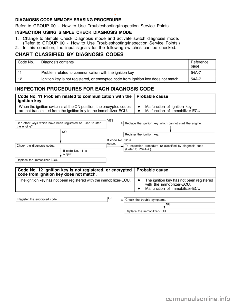
CHART CLASSIFIED BY DIAGNOSIS CODES
Code No.Diagnosis contentsReference
page
11Problem related to communication with the ignition key54A-7
12Ignition key is not registered, or encrypted code from ignition key does not match.54A-7
INSPECTION PROCEDURES FOR EACH DIAGNOSIS CODE
Code No. 11 Problem related to communication with the
ignition keyProbable cause
When the ignition switch is at the ON position, the encrypted codes
are not transmitted from the ignition key to the immobilizer-ECU.D
Malfunction of ignition key
D
Malfunction of immobilizer-ECU
YES
NOCan otherkeys which havebeen registered beused to start
the engine?
If code No. 12 is
output
Check the diagnosis codes.To inspection procedure 12 classified by diagnosis code
(Refer to P.54A-7.)
Replace the immobilizer-ECU.
Register the ignition key.
If code No. 11 is
output
Replace the ignition key which cannot start the engine.
Code No. 12 Ignition key is not registered, or encrypted
code from ignition key does not match.Probable cause
The ignition key has not been registered with the immobilizer-ECU.D
The ignition key has not been registered
with the immobilizer-ECU.
D
Malfunction of immobilizer-ECU
OK
NG
Replace the immobilizer-ECU.
Check the trouble symptoms.Register the encrypted code.
www.WorkshopManuals.co.uk
Purchased from www.WorkshopManuals.co.uk
Page 1578 of 1839
CHASSIS ELECTRICAL-Ignition Switch and Immobilizer
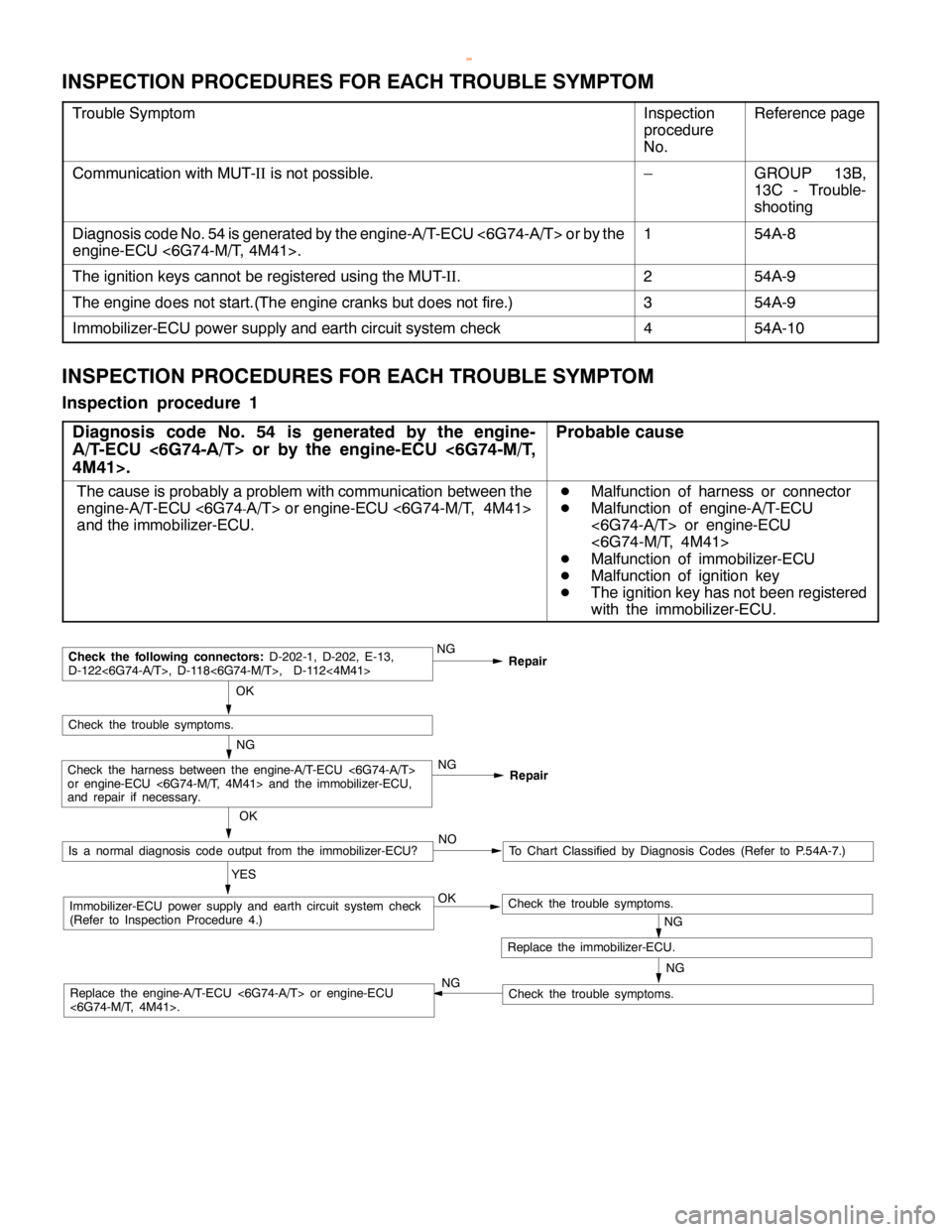
INSPECTION PROCEDURES FOR EACH TROUBLE SYMPTOM
Trouble SymptomInspection
procedure
No.Reference page
Communication with MUT-IIis not possible.–GROUP 13B,
13C - Trouble-
shooting
Diagnosis code No. 54 is generated by the engine-A/T-ECU <6G74-A/T> or by the
engine-ECU <6G74-M/T, 4M41>.154A-8
The ignition keys cannot be registered using the MUT-II.254A-9
The engine does not start.(The engine cranks but does not fire.)354A-9
Immobilizer-ECU power supply and earth circuit system check454A-10
INSPECTION PROCEDURES FOR EACH TROUBLE SYMPTOM
Inspection procedure 1
Diagnosis code No. 54 is generated by the engine-
A/T-ECU <6G74-A/T> or by the engine-ECU <6G74-M/T,
4M41>.
Probable cause
The cause is probably a problem with communication between the
engine-A/T-ECU <6G74
-A/T> orengine-ECU <6G74-M/T, 4M41>
and the immobilizer-ECU.
D
Malfunction of harness or connector
D
Malfunction of engine-A/T-ECU
<6G74-A/T> or engine-ECU
<6G74-M/T, 4M41>
D
Malfunction of immobilizer-ECU
D
Malfunction of ignition key
D
The ignition key has not been registered
with the immobilizer-ECU.
NG
NG OK
Immobilizer-ECU power supply and earth circuit system check
(Refer to Inspection Procedure 4.)
OK
Check the trouble symptoms.
NGRepair
NGCheck the following connectors:D-202-1, D-202, E-13,
D-122<6G74-A/T>, D-118<6G74-M/T>, D-112<4M41>
Repair
NGCheck the harness between the engine-A/T-ECU <6G74-A/T>
or engine-ECU <6G74-M/T, 4M41> and the immobilizer-ECU,
and repair if necessary.
Replace the immobilizer-ECU.
Check the trouble symptoms.
Check the trouble symptoms.Replace the engine-A/T-ECU <6G74-A/T> or engine-ECU
<6G74-M/T, 4M41>.OK
Is a normal diagnosis code output from the immobilizer-ECU?
YESTo Chart Classified by Diagnosis Codes (Refer to P.54A-7.) NO
NG
www.WorkshopManuals.co.uk
Purchased from www.WorkshopManuals.co.uk
Page 1579 of 1839
CHASSIS ELECTRICAL-Ignition Switch and Immobilizer
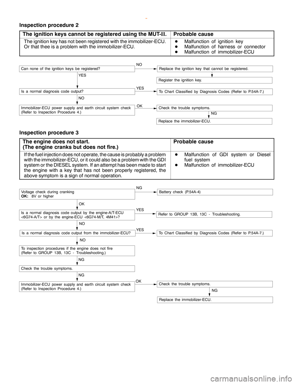
Inspection procedure 2
The ignition keys cannot be registered using the MUT-II.
Probable cause
The ignition key has not been registered with the immobilizer-ECU.
Or that thee is a problem with the immobilizer-ECU.D
Malfunction of ignition key
D
Malfunction of harness or connector
D
Malfunction of immobilizer-ECU
Register the ignition key.
YES
NO YESIs a normal diagnosis code output?
NOCan none of the ignitionkeys beregistered?Replace the ignition key that cannot be registered.
To Chart Classified by Diagnosis Codes (Refer to P.54A-7.)
OKImmobilizer-ECU power supply and earth circuit system check
(Refer to Inspection Procedure 4.)
NG
Replace the immobilizer-ECU.
Check the trouble symptoms.
Inspection procedure 3
The engine does not start.
(The engine cranks but does not fire.)
Probable cause
If the fuel injection does not operate, the cause is probably a problem
with the immobilizer-ECU, or it could also be a problem with the GDI
system or the DIESEL system. If an attempt has been made to start
the engine with a key that has not been properly registered, the
above symptom is a sign of normal operation.D
Malfunction of GDI system or Diesel
fuel system
D
Malfunction of immobilizer-ECU
NGBattery check (P.54A-4)
YES
NO
Refer to GROUP 13B, 13C - Troubleshooting.YES
NO
To Chart Classified by Diagnosis Codes (Refer to P.54A-7.)Is a normal diagnosis code output from the immobilizer-ECU?
OK
Voltage check during cranking
OK:8V or higher
NG
OKImmobilizer-ECU power supply and earth circuit system check
(Refer to Inspection Procedure 4.)
NG
Replace the immobilizer-ECU.
Check the trouble symptoms.
Check the trouble symptoms.
NG
To inspection procedures if the enginedoes not fire
(Refer to GROUP 13B, 13C - Troubleshooting.)
Is a normal diagnosis code output by the engine-A/T-ECU
<6G74-A/T> or by the engine-ECU <6G74-M/T, 4M41>?
www.WorkshopManuals.co.uk
Purchased from www.WorkshopManuals.co.uk
Page 1585 of 1839
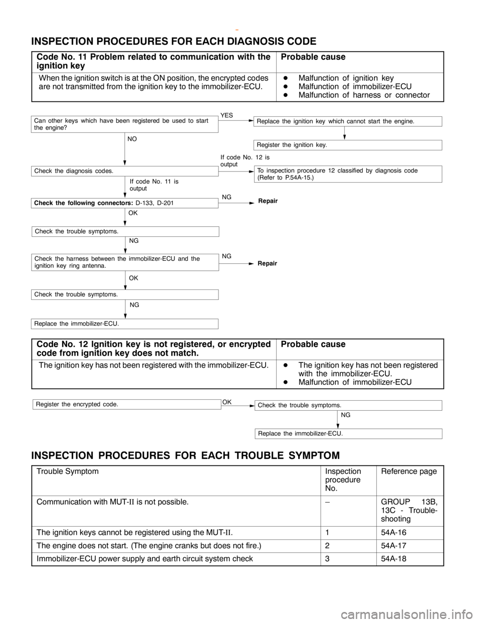
CHASSIS ELECTRICAL-Ignition Switch and Immobilizer <4D56>54A-15
INSPECTION PROCEDURES FOR EACH DIAGNOSIS CODE
Code No. 11 Problem related to communication with the
ignition keyProbable cause
When the ignition switch is at the ON position, the encrypted codes
are not transmitted from the ignition key to the immobilizer-ECU.D
Malfunction of ignition key
D
Malfunction of immobilizer-ECU
D
Malfunction of harness or connector
YES
NOCan otherkeys which havebeen registered beused to start
the engine?
If code No. 12 is
output
Check the diagnosis codes.To inspection procedure 12 classified by diagnosis code
(Refer to P.54A-15.)
Check the following connectors:D-133, D-201
Register the ignition key.
If code No. 11 is
output
OK
NG
Check the trouble symptoms.
Check the harness between the immobilizer-ECU and the
ignition key ring antenna.NG
OKNG
Check the trouble symptoms.
Replace the immobilizer-ECU.NGRepair
Repair
Replace the ignition key which cannot start the engine.
Code No. 12 Ignition key is not registered, or encrypted
code from ignition key does not match.Probable cause
The ignition key has not been registered with the immobilizer-ECU.D
The ignition key has not been registered
with the immobilizer-ECU.
D
Malfunction of immobilizer-ECU
OK
NG
Replace the immobilizer-ECU.
Check the trouble symptoms.Register the encrypted code.
INSPECTION PROCEDURES FOR EACH TROUBLE SYMPTOM
Trouble SymptomInspection
procedure
No.Reference page
Communication with MUT-IIis not possible.–GROUP 13B,
13C - Trouble-
shooting
The ignition keys cannot be registered using the MUT-II.154A-16
The engine does not start. (The engine cranks but does not fire.)254A-17
Immobilizer-ECU power supply and earth circuit system check354A-18
www.WorkshopManuals.co.uk
Purchased from www.WorkshopManuals.co.uk