2000 MITSUBISHI MONTERO check engine
[x] Cancel search: check enginePage 991 of 1839

AUTOMATIC TRANSMISSION -Troubleshooting
Ter-
minal
No.Check itemInspection conditionsStandard value
1Shift actuatorTransfer shift lever position: 2H®4H5.6 V®11.0 V®
5.6 V
3Shift actuatorTransfer shift lever position: 4H®2H5.6 V®11.0 V®
5.6 V
5Accelerator pedal positionAccelerator pedal: Fully closed (engine stopped)0.985 - 1.085 V
sensor (APS)Accelerator pedal: Fully open (engine stopped)4.0 V or higher
7Front propeller shaft speed
sensorMeasure the voltage between terminals 7 and 18 using
an oscilloscope.
Engine: 2 000 r/min
Shift range: 4thOscilloscope check
procedure (Refer to
P. 23-69
9Rear propeller shaft speed
sensorMeasure the voltage between terminals 9 and 18 using
an oscilloscope.
Engine: 2 000 r/min
Shift range: 4thOscilloscope check
procedure (Refer to
P. 23-69
11Diagnosis outputWhen normal (no diagnosis codes are output)0 V and 5 V alterna-
tes
13Power supplyIgnition switch: OFF0V
Ignition switch: ONSystem voltage
18Sensor earthAt all times0.5 V or less
20Transfer lever switch 2HTransfer shift lever position: 2HSystem voltage
Transfer shift lever position: Other than the above0V
21Transfer lever switch 4HTransfer shift lever position: 4HSystem voltage
Transfer shift lever position: Other than the above0V
22Transfer lever switch 4HLcTransfer shift lever position: 4HLcSystem voltage
Transfer shift lever position: Other than the above0V
23Transfer lever switch 4LLcTransfer shift lever position: 4LLcSystem voltage
Transfer shift lever position: Other than the above0V
24Diagnosis control––
25EarthAt all times0V
26EarthAt all times0V
31Backup power supplyAt all timesSystem voltage
32Inhibitor switch NSelector lever position: NSystem voltage
Selector lever position: Other than the above0V
33Inhibitor switch PSelector lever position: PSystem voltage
Selector lever position: Other than the above0V
34Stop lamp switchBrake pedal: DepressedSystem voltage
Brake pedal: Released0V
35EarthAt all times0V
37Rear wheel indicator lampOther than during transfer selectionSystem voltage
38Front wheel indicator lampDuring 4WDSystem voltage
39Earth <6G7>At all times0V
www.WorkshopManuals.co.uk
Purchased from www.WorkshopManuals.co.uk
Page 1165 of 1839

POWER PLANT MOUNT - No.1 Crossmember32-7
No.1 CROSSMEMBER
REMOVAL AND INSTALLATION
Caution
1. Before removing the steering wheel and airbag module assembly, always refer to GROUP 52B
- Service Precautions, Airbag Module and Clock Spring. Also, set the front wheels so that
they are facing straight forward, and remove the ignition key. If you fail to do this, the SRS
clock spring will be damaged, causing the SRS airbag to be inoperative and serious injury.
2. *: Indicates parts which should be initially tightened, and then fully tightened after placing
the vehicle horizontally and loading the full weight of the engine on the vehicle body.
Pre-removal Operation
DUnder Cover Removal
DDrive Shaft Removal
(Refer to GROUP 26.)
DDifferential Carrier and No.2 Crossmember
Assembly Removal (Refer to GROUP 26 -
Freewheel Assembly and Differential Carrier.)
DUpper Arm Removal
(Refer to GROUP 33A.)
DLower Arm Removal
(Refer to GROUP 33A.)
DStabilizer Bar Removal
(Refer to GROUP 33A.)
DEngine Oil Cooler Removal<6G7>
(Refer to GROUP 12.)
DAir Cleaner Removal<4M4>
(Refer to GROUP 15.)
DIntercooler Removal<4M4>
(Refer to GROUP 15.)
DEngine Cover Removal
(Refer to GROUP 11A - Timing Belt.)
DRadiator Removal
(Refer to GROUP 14.)
DPower Steering Fluid Draining
(Refer to GROUP 37A - On - vehicle Service.)Post - installation Operations
DDifferential Carrier and No.2 Crossmember
Assembly Installation (Refer to GROUP 26 -
Freewheel Assembly and Differential Carrier.)
DDrive Shaft Installation
(Refer to GROUP 26.)
DLower Arm Installation
(Refer to GROUP 33A.)
DUpper Arm Installation
(Refer to GROUP 33A.)
DStabilizer Bar Installation
(Refer to GROUP 33A.)
DAir Cleaner Installation<4M4>
(Refer to GROUP 15.)
DIntercooler Installation<4M4>
(Refer to GROUP 15.)
DRadiator Installation
(Refer to GROUP 14.)
DEngine Oil Cooler Installation
(Refer to GROUP 12.)
DPower Steering Fluid Supplying
(Refer to GROUP 37A - On - vehicle Service.)
DPower Steering Fluid Line Bleeding
(Refer to GROUP 37A - On - vehicle Service.)
DPress the dust cover with a finger tocheck whether
the dust cover is cracked or damaged.
DChecking Steering Wheel Position with Wheels
StraightAhead
DFront Wheel AlignmentCheck and Adjustment
(Refer to GROUP 37A - On - vehicle Service.)
DUnder Cover Installation
DEngine Cover Installation
(Refer to GROUP 11A - Timing Belt.)
www.WorkshopManuals.co.uk
Purchased from www.WorkshopManuals.co.uk
Page 1210 of 1839

35A-2
BASIC BRAKE
SYSTEM
CONTENTS
GENERAL INFORMATION 3..................
SERVICE SPECIFICATIONS 5.................
LUBRICANTS 6..............................
SPECIAL TOOLS 6..........................
TROUBLESHOOTING
ON-VEHICLE SERVICE 19...................
Brake Pedal Check and Adjustment 19..........
Hydraulic Brake Booster (HBB) Operation Check
HBB Check
HBB Motor Relay Continuity Check
Brake Booster Operating Test
Check Valve Operation Check
Load Sensing Spring Length Check and
Adjustment
Load Sensing Proportioning Valve Function
Test
Bleeding
Brake Fluid Level Sensor Check 30.............
Brake Booster Vacuum Switch Check
Disc Brake Pad Check and Replacement 31.....
Disc Brake Rotor Check 32.....................
Brake Disc Thickness Check 32.................
Brake Disc Run-out Check and Correction 33....
BRAKE PEDAL 34..........................
HYDRAULIC BRAKE BOOSTER (HBB)
HBB BUZZER
MASTER CYLINDER AND BRAKE
BOOSTER
Master Cylinder 43.............................
FRONT DISC BRAKE 44....................
REAR DISC BRAKE 49......................
LOAD SENSING PROPORTIONING
VALVE
www.WorkshopManuals.co.uk
Purchased from www.WorkshopManuals.co.uk
Page 1217 of 1839
BASIC BRAKE SYSTEM -Troubleshooting35A-9
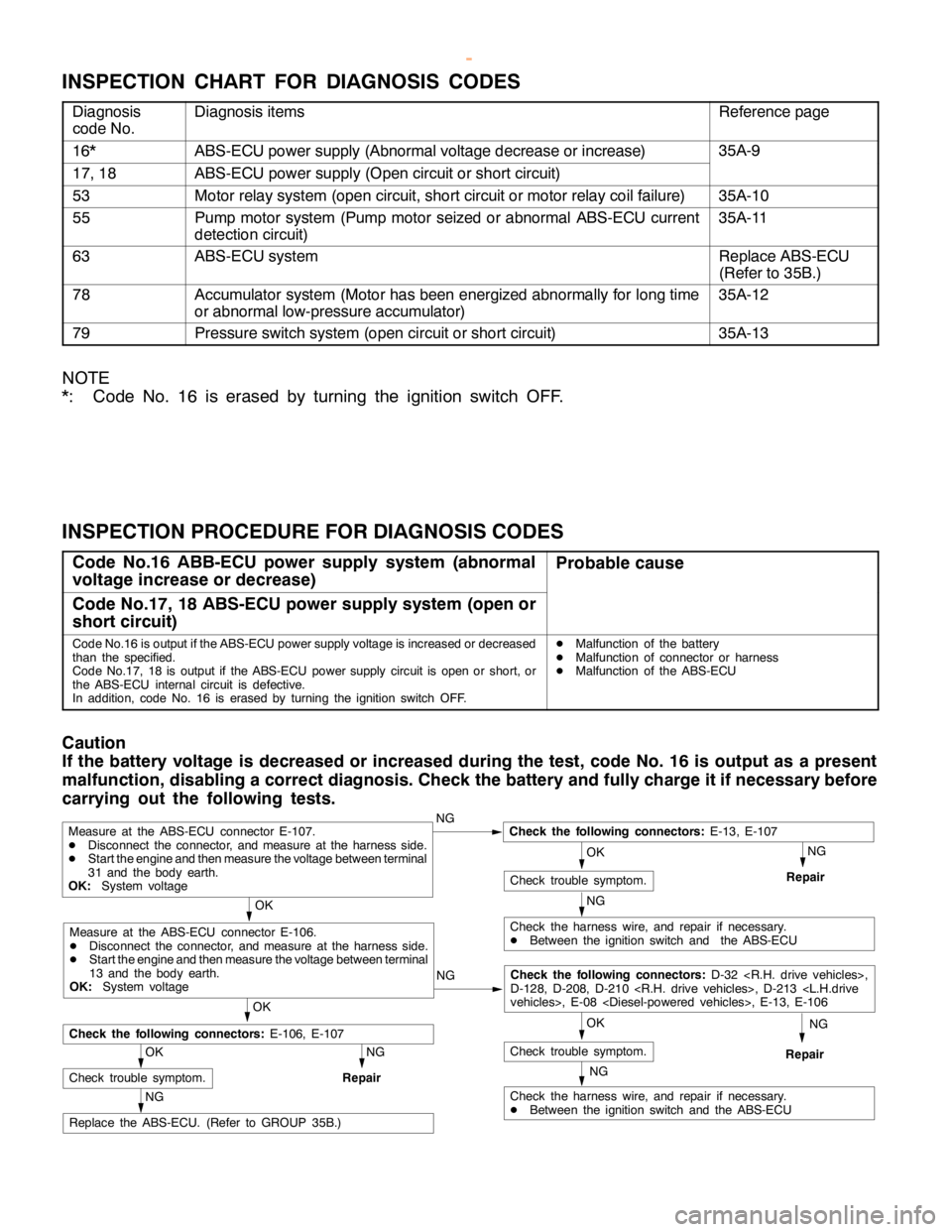
INSPECTION CHART FOR DIAGNOSIS CODES
Diagnosis
code No.Diagnosis itemsReference page
16*ABS-ECU power supply (Abnormal voltage decrease or increase)35A-9
17, 18ABS-ECU power supply (Open circuit or short circuit)
53Motor relay system (open circuit, short circuit or motor relay coil failure)35A-10
55Pump motor system (Pump motor seized or abnormal ABS-ECU current
detection circuit)35A-11
63ABS-ECU systemReplace ABS-ECU
(Refer to 35B.)
78Accumulator system (Motor has been energized abnormally for long time
or abnormal low-pressure accumulator)35A-12
79Pressure switch system (open circuit or short circuit)35A-13
NOTE
*: Code No. 16 is erased by turning the ignition switch OFF.
INSPECTION PROCEDURE FOR DIAGNOSIS CODES
Code No.16 ABB-ECU power supply system (abnormal
voltage increase or decrease)Probable cause
Code No.17, 18 ABS-ECU power supply system (open or
short circuit)
Code No.16 is output if the ABS-ECU power supply voltage is increased or decreased
than the specified.
Code No.17, 18 is output if the ABS-ECU power supply circuit isopen orshort, or
the ABS-ECU internal circuit is defective.
In addition, code No. 16 is erased by turning the ignition switch OFF.DMalfunction of the battery
DMalfunction of connector or harness
DMalfunction of the ABS-ECU
Caution
If the battery voltage is decreased or increased during the test, code No. 16 is output as a present
malfunction, disabling a correct diagnosis. Check the battery and fully charge it if necessary before
carrying out the following tests.
NG
NG
OK
NG
Replace the ABS-ECU. (Refer to GROUP 35B.)
OK
Check trouble symptom.
NG
Repair
NG
Check the harness wire, and repair if necessary.
DBetween the ignition switch and the ABS-ECU
OK
Check trouble symptom.
Measure at the ABS-ECU connector E-107.
DDisconnect the connector, and measure at the harness side.
DStart theengine and then measure the voltage between terminal
31 and the body earth.
OK:System voltageNGCheck the following connectors:E-13, E-107
Repair
OK
Check the following connectors:E-106, E-107
NG
Check the harness wire, and repair if necessary.
DBetween the ignition switch and the ABS-ECU
OK
Check trouble symptom.
Measure at the ABS-ECU connector E-106.
DDisconnect the connector, and measure at the harness side.
DStart theengine and then measure the voltage between terminal
13 and the body earth.
OK:System voltageNG
Check the following connectors:D-32
D-128, D-208, D-210
Repair
www.WorkshopManuals.co.uk
Purchased from www.WorkshopManuals.co.uk
Page 1221 of 1839
BASIC BRAKE SYSTEM -Troubleshooting35A-13
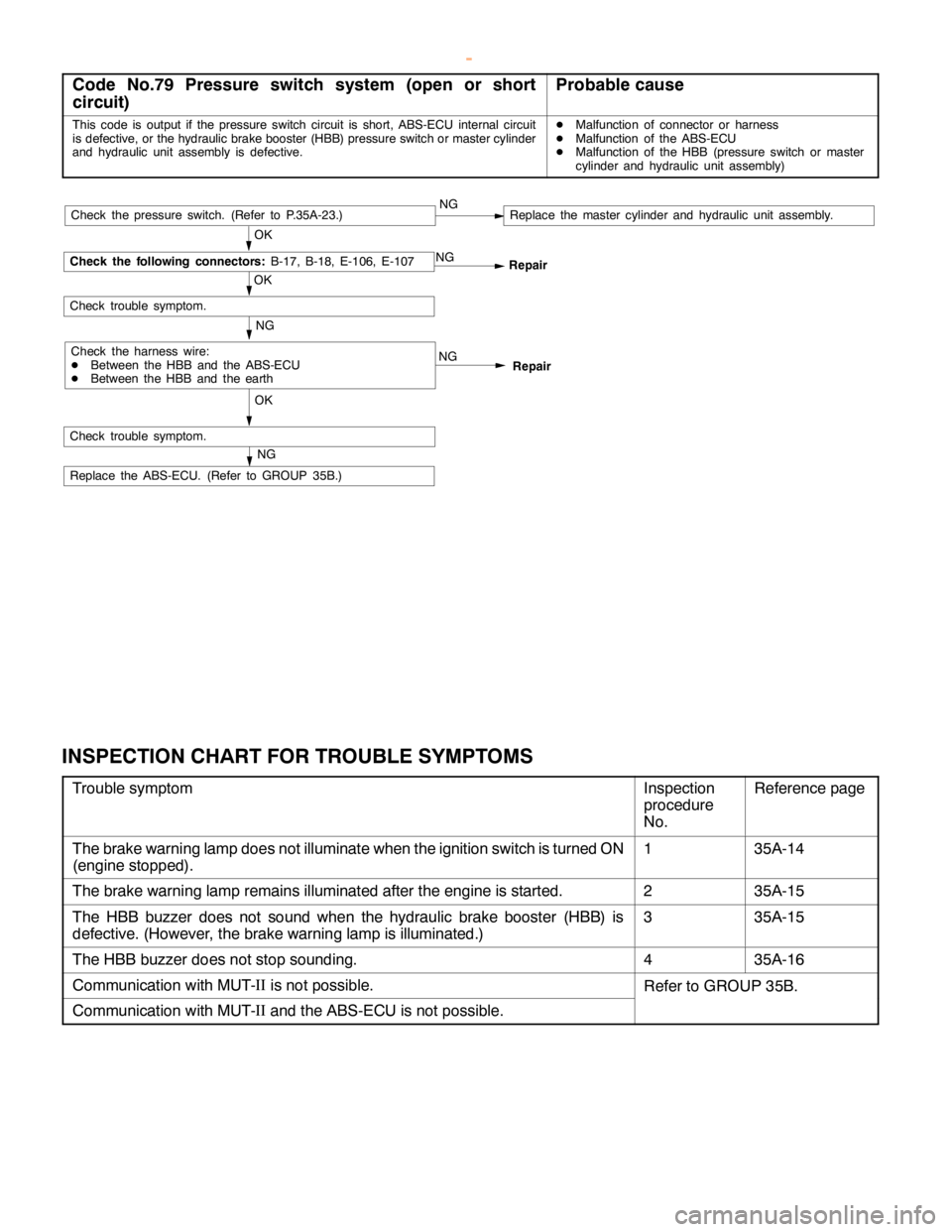
Code No.79 Pressure switch system (open or short
circuit)Probable cause
This code is output if the pressure switch circuit is short, ABS-ECU internal circuit
is defective, or the hydraulic brake booster (HBB) pressure switch or master cylinder
and hydraulic unit assembly is defective.DMalfunction of connector or harness
DMalfunction of the ABS-ECU
DMalfunction of the HBB (pressure switch or master
cylinder and hydraulic unit assembly)
NG
Repair
NG
OKRepair NG
OK
Check trouble symptom.
Check the following connectors:
B-17, B-18, E-106, E-107
Check the harness wire:
DBetween the HBB and the ABS-ECU
DBetween the HBB and the earthNG
Check trouble symptom.
Replace the ABS-ECU. (Refer to GROUP 35B.)
NG
OKCheck the pressure switch. (Refer to P.35A-23.)Replace the master cylinder and hydraulic unit assembly.
INSPECTION CHART FOR TROUBLE SYMPTOMS
Trouble symptomInspection
procedure
No.Reference page
The brake warning lamp does not illuminate when the ignition switch is turned ON
(engine stopped).135A-14
The brake warning lamp remains illuminated after the engine is started.235A-15
The HBB buzzer does not sound when the hydraulic brake booster (HBB) is
defective. (However, the brake warning lamp is illuminated.)335A-15
The HBB buzzer does not stop sounding.435A-16
Communication with MUT-II
is not possible.Refer to GROUP 35B.
Communication with MUT-II
and the ABS-ECU is not possible.
www.WorkshopManuals.co.uk
Purchased from www.WorkshopManuals.co.uk
Page 1222 of 1839
BASIC BRAKE SYSTEM -Troubleshooting35A-14
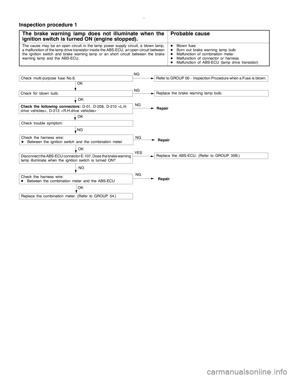
Inspection procedure 1
The brake warning lamp does not illuminate when the
ignition switch is turned ON (engine stopped).
Probable cause
The cause may be anopencircuit in thelamppower supply circuit, a blown lamp,
a malfunction of the lampdrive transistor inside the ABS-ECU, anopencircuit between
the ignition switch and brake warninglamp or anshort circuit between the brake
warning lamp and theABS-ECU.DBlown fuse
DBurn out brake warninglamp bulb
DMalfunction of combination meter
DMalfunction of connector or harness
DMalfunction of ABS-ECU (lamp drive transistor)
Repair NG NG
NO
Replace the ABS-ECU. (Refer to GROUP 35B.)
Repair
Repair
NG
OK
Check for blown bulb.Replace the brake warninglamp bulb.
OK
Check the following connectors:
D-01, D-208, D-210
NG
Replace the combination meter. (Refer to GROUP 54.)
OK
Check trouble symptom.
OK
YES
Check multi-purpose fuse No.6.NGRefer to GROUP 00 – Inspection Procedure when a Fuse is blown.
Check the harness wire:
DBetween the ignition switch and the combination meter
Check the harness wire:
DBetween the combination meter and the ABS-ECU
Disconnect the ABS-ECU connector E-107. Does the brake warning
lamp illuminatewhen the ignition switch is turned ON?
NG
OK
www.WorkshopManuals.co.uk
Purchased from www.WorkshopManuals.co.uk
Page 1223 of 1839
BASIC BRAKE SYSTEM -Troubleshooting35A-15
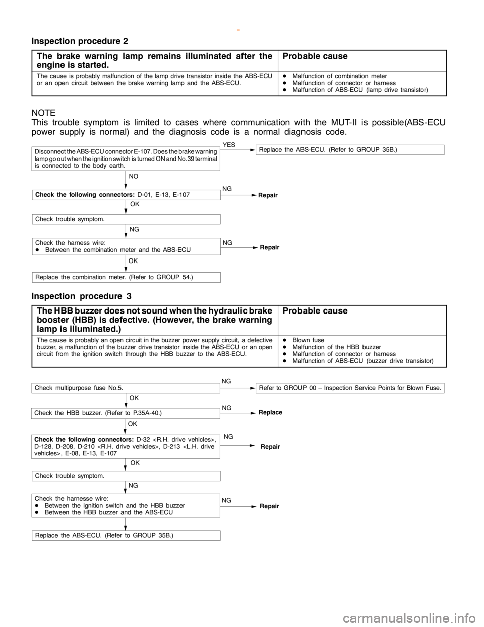
Inspection procedure 2
The brake warning lamp remains illuminated after the
engine is started.
Probable cause
The cause is probably malfunction of thelampdrive transistor inside the ABS-ECU
or an opencircuit between the brake warninglamp and theABS-ECU.DMalfunction of combination meter
DMalfunction of connector or harness
DMalfunction of ABS-ECU (lamp drive transistor)
NOTE
This trouble symptom is limited to cases where communication with the MUT-II is possible(ABS-ECU
power supply is normal) and the diagnosis code is a normal diagnosis code.
Repair NG
Repair
Replace the combination meter. (Refer to GROUP 54.)
OK
YESReplace the ABS-ECU. (Refer to GROUP 35B.)
NO
Disconnect the ABS-ECU connector E-107. Does the brake warning
lamp go outwhen the ignition switch is turned ON and No.39 terminal
is connected to the body earth.
OK
Check the following connectors:
D-01, E-13, E-107
Check trouble symptom.
Check the harness wire:
DBetween the combination meter and the ABS-ECUNG
NG
Inspection procedure 3
The HBB buzzer does not sound when the hydraulic brake
booster (HBB) is defective. (However, thebrake warning
lamp is illuminated.)
Probable cause
The cause is probably anopencircuit in the buzzer power supply circuit, a defective
buzzer, a malfunction of the buzzer drive transistor inside the ABS-ECU or anopen
circuit from the ignition switch through the HBB buzzer to the ABS-ECU.DBlown fuse
DMalfunction of the HBB buzzer
DMalfunction of connector or harness
DMalfunction of ABS-ECU (buzzer drive transistor)
Replace the ABS-ECU. (Refer to GROUP 35B.)
Repair NG
Repair
NG
OK
Check the HBB buzzer. (Refer to P.35A-40.)
OK
Check the following connectors:
D-32
D-128, D-208, D-210
NG
OK
Check trouble symptom.
Check multipurpose fuse No.5.NGRefer to GROUP 00 – Inspection Service Points for Blown Fuse.
Check the harnesse wire:
DBetween the ignition switch and the HBB buzzer
DBetween the HBB buzzer and the ABS-ECUNGReplace
www.WorkshopManuals.co.uk
Purchased from www.WorkshopManuals.co.uk
Page 1281 of 1839
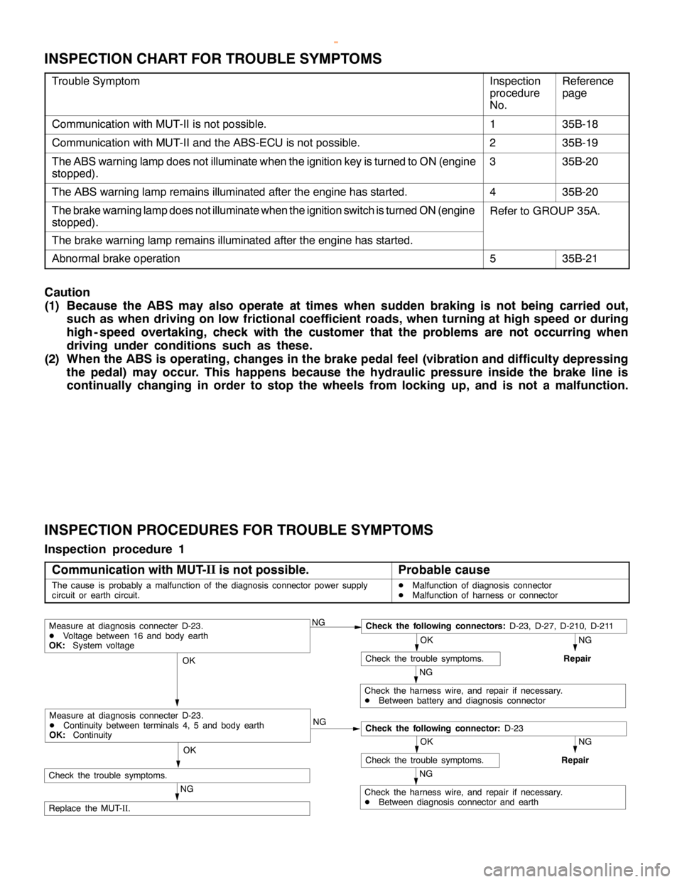
ABS <4WD> -Troubleshooting35B-18
INSPECTION CHART FOR TROUBLE SYMPTOMS
Trouble SymptomInspection
procedure
No.Reference
page
Communication with MUT-II is not possible.135B-18
Communication with MUT-II and the ABS-ECU is not possible.235B-19
The ABS warning lamp does not illuminate when the ignition key is turned to ON (engine
stopped).335B-20
The ABS warning lamp remains illuminated after the engine has started.435B-20
The brake warning lamp does not illuminate when the ignition switch is turned ON (engine
stopped).Refer to GROUP 35A.
The brake warning lamp remains illuminated after the engine has started.
Abnormal brake operation535B-21
Caution
(1) Because the ABS may also operate at times when sudden braking is not being carried out,
such as when driving on low frictional coefficient roads, when turning at high speed or during
high - speed overtaking, check with the customer that the problems are not occurring when
driving under conditions such as these.
(2) When the ABS is operating, changes in the brake pedal feel (vibration and difficulty depressing
the pedal) may occur. This happens because the hydraulic pressure inside the brake line is
continually changing in order to stop the wheels from locking up, and is not a malfunction.
INSPECTION PROCEDURES FOR TROUBLE SYMPTOMS
Inspection procedure 1
Communication with MUT-II
is not possible.
Probable cause
The cause is probably a malfunction of the diagnosis connector power supply
circuit or earth circuit.DMalfunction of diagnosis connector
DMalfunction of harness or connector
NGCheck the following connectors:D-23, D-27, D-210, D-211
NG
Repair
OK
Check the trouble symptoms.
NG
Check the harness wire, and repair if necessary.
DBetween battery and diagnosis connector
OK
NG
NG
Repair
OK
Check the trouble symptoms.
NG
Check the harness wire, and repair if necessary.
DBetween diagnosis connector and earth
OK
NG
Replace the MUT-
II.
Measure at diagnosis connecter D-23.
DVoltage between 16 and body earth
OK:System voltage
Check the following connector:D-23
Measure at diagnosis connecter D-23.
DContinuity between terminals 4, 5 and body earth
OK:Continuity
Check the trouble symptoms.
www.WorkshopManuals.co.uk
Purchased from www.WorkshopManuals.co.uk