Page 323 of 1839

GDI -Troubleshooting 13A-109
Item
No.Reference
page Inspection
procedure
No. Normal condition Requirements Check items
77Accelerator
pedal positionIgnition switch: ONRelease the accel-
erator pedal.985 - 1085 mVCode
No.P122513A-68
sensor (2nd
channel)
Depress the accel-
erator pedal gradu-
ally.Increases in re-
sponse to the ped-
al depression
stroke.
Depress the accel-
erator pedal fully.4,000 mV or more
78Accelerator
pedal positionIgnition switch: ONRelease the accel-
erator pedal.985 - 1085 mVCode
No.P022013A-50
sensor (1st
channel) *3Depress the accel-
erator pedal gradu-
ally.Increases in re-
sponse to pedal
depression stroke.
Depress the accel-
erator pedal fully.4,200 - 4,800 mV
79Throttle posi-
tion sensorDEngine coolant
temperature:Release the accel-
erator pedal.400 - 800 mVCode
No.012013A-25
(1st channel)80 - 95_C
DIgnition switch:
ON (Engine
stopped)
Depress the accel-
erator pedal gradu-
ally.Increases in re-
sponse to pedal
depression stroke.
4,600 - 5,200 mV4,200 - 4,800 mV
Engine: AfterNo load450 - 1,000 mV
warm-up, idling
A/C switch: OFF®
ONIncreases by 100 -
600 mV.
99Fuel injection
modeEngine: After warm
upIdling (after four
minutes or more
have passed since
engine start)Lean compression--
2,500 r/minStoichiometric
metric feedback
Sudden racing after
idle positionOpen loop
www.WorkshopManuals.co.uk
Purchased from www.WorkshopManuals.co.uk
Page 324 of 1839

GDI -Troubleshooting 13A-110
ACTUATOR TEST REFERENCE TABLE
Item
No.Inspection
itemDrive contentsInspection contentsNormal conditionInspection
procedure
No.Reference
page
01InjectorsCut fuel to No. 1
injectorEngine:
After havingIdling condition
becomes differentCode No.
P020113A-38
02Cut fuel to No. 2
injector
warmed up/Engine
is idling
(Cut the fuel supply(becomes unsta-
ble).
Code No.
P020213A-40
03Cut fuel to No. 3
injectorto each injector in
turn and check
cylinders whichCode No.
P020313A-42
04Cut fuel to No. 4
injectordon’t affect idling.)Code No.
P020413A-44
05Cut fuel to No. 5
injectorCode No.
P020513A-46
06Cut fuel to No. 6
injectorCode No.
P020613A-48
07Fuel pump
(low pressure)Fuel pump
operates and
fuel is recirculated.Ignition switch: ONSound of opera-
tion is heard.Procedure
No. 2913A-101
08Purge
control
solenoid valveSolenoid valve
turns from OFF to
ON.Ignition switch: ONSound of opera-
tion can be heard
when solenoid
valve is
driven.Code No.
P044313A-62
17Basic ignition
timingSet the engine-
ECU to ignition
timing adjustment
modeIdling after engine
warm up5_BTDC--
21Condenser fanDrive the fan motorIgnition switch: ONThe fan motor
operatesProcedure
No.2113A-95
34Electronic-
controlled
throttle valve
systemStop the throttle
control servo.Ignition switch: ONThrottle valve is
opened slightly.Code No.
P122013A-64
www.WorkshopManuals.co.uk
Purchased from www.WorkshopManuals.co.uk
Page 341 of 1839
Page 409 of 1839

GDI -Troubleshooting 13A-195
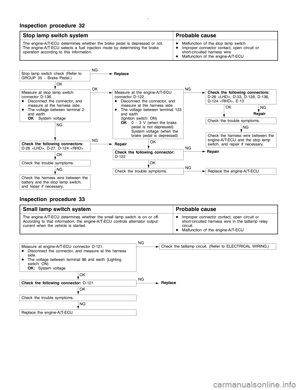
Inspection procedure 32
Stop lamp switch system
Probable cause
The engine-A/T-ECU determines whether the brakepedal is depressed or not.
The engine-A/T-ECU selects a fuel injectionmode by determining thebrake
operation according to this information.DMalfunction of the stoplampswitch
DImproper connector contact,opencircuit or
short-circuited harness wire
DMalfunction of the engine-A/T-ECU
NG
Check the following connectors:
D-26 , D-27, D-124 NG
Repair
OK
Check the trouble symptoms.
OK
Check the following connector:
D-122NG
Repair
Stoplampswitch check (Refer to
GROUP 35 - Brake Pedal.)NG
Replace
OK
Measure at stoplampswitch
connector D-136.
DDisconnect the connector, and
measure at the harness side.
DThe voltage between terminal 2
and earth
OK
System voltageOKMeasure at the engine-A/T-ECU
connector D-122.
DDisconnect the connector, and
measure at the harness side.
DThe voltage between terminal 123
and earth
(Ignition switch: ON)
OK
0 - 3 V (when the brake
pedal is not depressed)
System voltage (when the
brakepedal is depressed)NG
NG
Repair OK
Check the trouble symptoms.
NG
Check the harness wire between the
engine-A/T-ECU and the stoplamp
switch, and repair if necessary.
NG
Check the harness wire between the
battery and the stoplampswitch,
and repair if necessary.
OK
Check the trouble symptoms.NGReplace the engine-A/T-ECU.
Check the following connectors:
D-26 , D-33, D-128, D-136,
D-124 , E-13
Inspection procedure 33
Small lamp switch system
Probable cause
The engine-A/T-ECU determines whether the smalllampswitch is on or off.
According to that information, the engine-A/T-ECU controls alternator output
current when the vehicle is started.DImproper connector contact,opencircuit or
short-circuited harness wire in thetaillamprelay
circuit.
DMalfunction of the engine-A/T-ECU
OK
Check the following connector:
D-121NGReplace
Measure at engine-A/T-ECU connector D-121.
DDisconnect the connector, and measure at the harness
side.
DThe voltage between terminal 86 and earth (Lighting
switch: ON)
OK:
System voltageNGCheck thetaillampcircuit. (Refer to ELECTRICAL WIRING.)
OK
Check the trouble symptoms.
NG
Replace the engine-A/T-ECU.
www.WorkshopManuals.co.uk
Purchased from www.WorkshopManuals.co.uk
Page 416 of 1839
Page 475 of 1839

GDI -Troubleshooting13A-6
Item
No.Refer-
ence
page Inspec-
tion pro-
cedure
No. Normal condition Inspection contents Inspection
item
81LLearned
valueEngine: Warm, 2,500 r/min without any load
(during closed loop lambda control)- 10 - 10 %Code
No.
P017013A-34*
82LClosed loop
controlEngine: Warm, 2,500 r/min without any load
(during closed loop lambda control)- 25 - 25 %Code
No.
P017013A-34*
87LEngine loadEngine: After having
warmed upIdling (more than 4
minutes later after
the engine has
started)20 - 40 %--
2,500 r/min10 - 30 %
8ALThrottle
position
sensor(1st
DEngine: After hav-
ing warmed up
DIgnitionswitch:ON
Release the
accelerator pedal.0 - 20 %Code
No.
P0120
13A-25*
sensor(1st
channel)
(throttle
valve angle)DIgnition switch:ON
(Engine: stopped)Depress the
accelerator pedal.Increase in
proportion to the
pedal strokeP0120
Depress the
accelerator pedal
fully.80 - 100 %
NOTE
L: will not displayed if service data is selected on the check mode.
*: Refer to the 2001 PAJERO Workshop Manual (Pub.No. PWJE0001)
www.WorkshopManuals.co.uk
Purchased from www.WorkshopManuals.co.uk
Page 478 of 1839
DIESEL FUEL <4D5>
Click on the applicable bookmark to selected the required model year.
www.WorkshopManuals.co.uk
Purchased from www.WorkshopManuals.co.uk
Page 491 of 1839
DIESEL FUEL <4M4>
Click on the applicable bookmark to selected the required model year.
www.WorkshopManuals.co.uk
Purchased from www.WorkshopManuals.co.uk