2000 MITSUBISHI MONTERO check engine
[x] Cancel search: check enginePage 915 of 1839
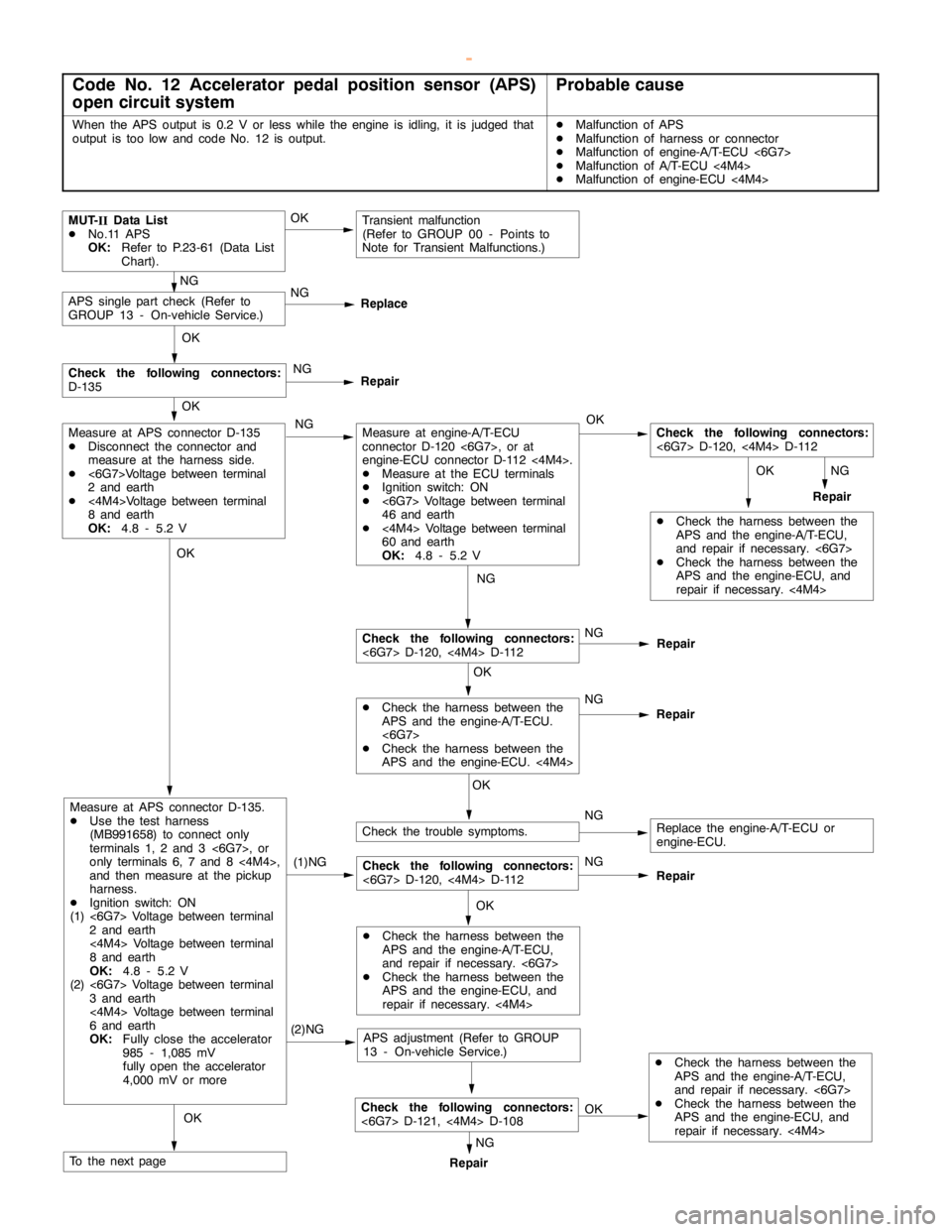
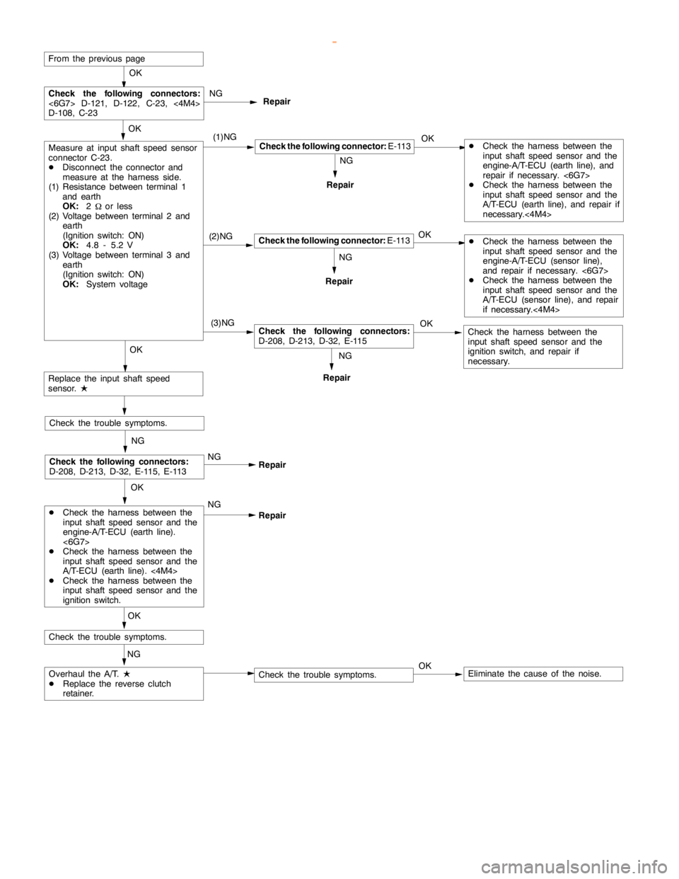
Page 916 of 1839
AUTOMATIC TRANSMISSION -Troubleshooting AUTOMATIC TRANSMISSION -Troubleshooting AUTOMATIC TRANSMISSION -Troubleshooting 23-15
OK
OK
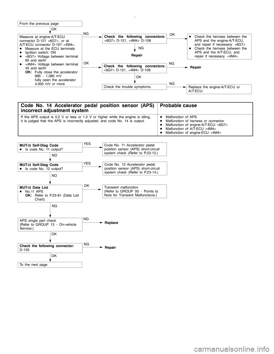
From the previouspage
OK
Replace the engine-A/T-ECU or
A/T-ECU. OK
Measure at engine-A/T-ECU
connector D-121 <6G7>, or at
A/T-ECU connector D-107 <4M4>.
DMeasure at the ECU terminals
DIgnition switch: ON
D<6G7> Voltage between terminal
95 and earth
D<4M4> Voltage between terminal
45 and earth
OK:Fully close the accelerator
985 - 1,085 mV
fullyopen the accelerator
4,000 mV or moreNG
NG
NG
Repair
Check the following connectors:
<6G7> D-121,<4M4>D-108
NG
Repair
Check the trouble symptoms.
Check the following connectors:
<6G7> D-121,<4M4>D-108
DCheck the harness between the
APS and the engine-A/T-ECU,
and repair if necessary. <6G7>
DCheck the harness between the
APS and the A/T-ECU, and
repair if necessary.<4M4>
Code No. 14 Accelerator pedal position sensor (APS)
incorrect adjustment systemProbable cause
If the APS output is 0.2 V or less or 1.2 V or higher while theengine is idling,
it is judged that the APS isincorrectly adjusted, and code No. 14 is output.DMalfunction of APS
DMalfunction of harness or connector
DMalfunction of engine-A/T-ECU <6G7>
DMalfunction of A/T-ECU<4M4>
DMalfunction of engine-ECU <4M4>
NGNO
YES
YES
MUT-
IISelf-Diag Code
DIs code No. 11 output?Code No. 11 Acceleratorpedal
position sensor (APS) short-circuit
system check (Refer to P.23-13.)
Code No. 12 Acceleratorpedal
position sensor (APS) short-circuit
system check (Refer to P.23-14.)
MUT-
IIData List
DNo.11 APS
OK:Refer to P.23-61 (Data List
Chart).
NG
ReplaceAPS single part check
(Refer to GROUP 13 - On-vehicle
Service.)
OK
NG
Repair
OK
Check the following connector:
D-135OK NO
Transient malfunction
(Refer to GROUP 00 - Points to
Note for Transient Malfunctions.)
MUT-
IISelf-Diag Code
DIs code No. 12 output?
To the nextpage
www.WorkshopManuals.co.uk
Purchased from www.WorkshopManuals.co.uk
Page 917 of 1839
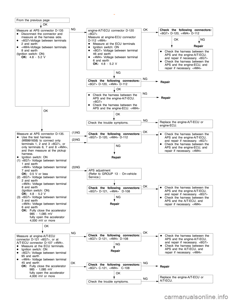
Page 918 of 1839
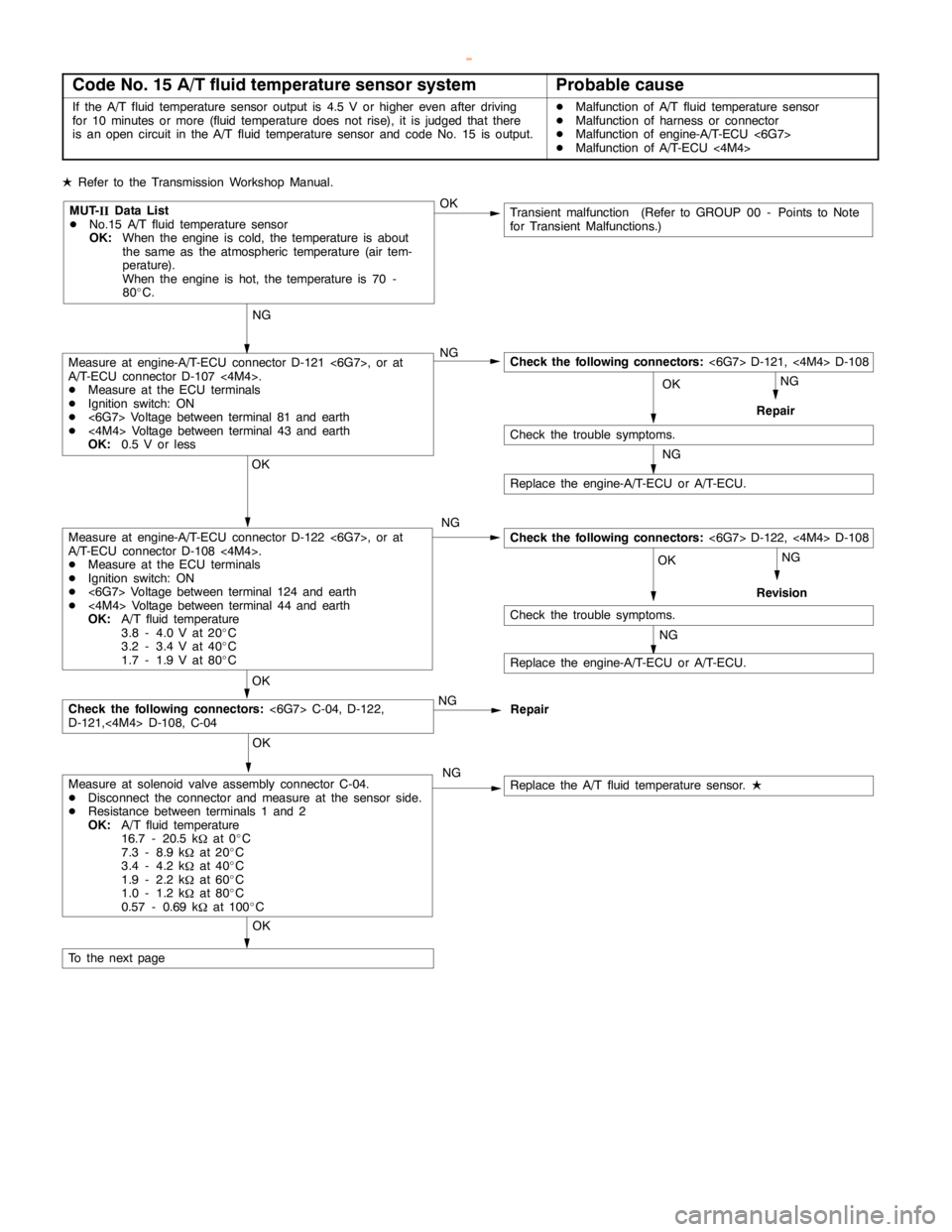
Page 919 of 1839
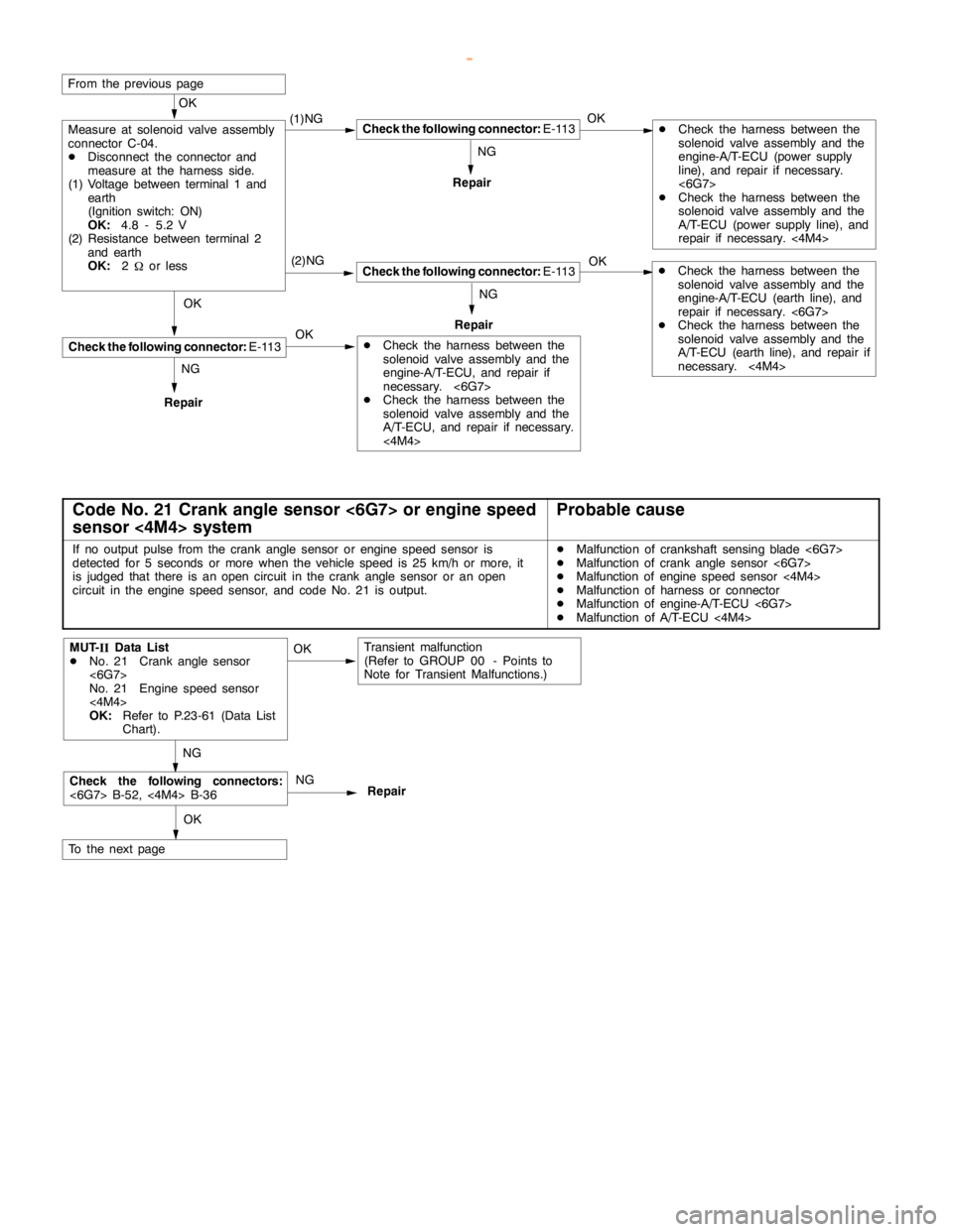
AUTOMATIC TRANSMISSION -Troubleshooting AUTOMATIC TRANSMISSION -Troubleshooting AUTOMATIC TRANSMISSION -Troubleshooting 23-18
OK
(2)NG
From the previouspage
Repair
OK
Repair
Check the following connector:E-113
Repair
Measure at solenoid valve assembly
connector C-04.
DDisconnect the connector and
measure at the harness side.
(1) Voltage between terminal 1 and
earth
(Ignition switch: ON)
OK:4.8 - 5.2 V
(2) Resistance between terminal 2
and earth
OK:2
Wor lessOK
OK
OKNG NG (1)NG
NG
DCheck the harness between the
solenoid valve assembly and the
engine-A/T-ECU (earth line), and
repair if necessary. <6G7>
DCheck the harness between the
solenoid valve assembly and the
A/T-ECU (earth line), and repair if
necessary.<4M4>
DCheck the harness between the
solenoid valve assembly and the
engine-A/T-ECU (power supply
line), and repair if necessary.
<6G7>
DCheck the harness between the
solenoid valve assembly and the
A/T-ECU (power supply line), and
repair if necessary.<4M4>
DCheck the harness between the
solenoid valve assembly and the
engine-A/T-ECU, and repair if
necessary. <6G7>
DCheck the harness between the
solenoid valve assembly and the
A/T-ECU, and repair if necessary.
<4M4>Check the following connector:E-113
Check the following connector:E-113
Code No. 21 Crank angle sensor <6G7> or engine speed
sensor <4M4> systemProbable cause
If no output pulse from the crankanglesensor orenginespeed sensor is
detected for 5 seconds or more when the vehicle speed is 25 km/h or more, it
is judged that there is an opencircuit in the crankanglesensor or anopen
circuit in theenginespeed sensor, and code No. 21 is output.DMalfunction of crankshaft sensingblade<6G7>
DMalfunction of crankanglesensor <6G7>
DMalfunction of enginespeed sensor<4M4>
DMalfunction of harness or connector
DMalfunction of engine-A/T-ECU <6G7>
DMalfunction of A/T-ECU<4M4>
Check the following connectors:
<6G7> B-52,<4M4>B-36Repair
Transient malfunction
(Refer to GROUP 00 - Points to
Note for Transient Malfunctions.)
OK NG
NGOKMUT-
IIData List
DNo. 21 Crankanglesensor
<6G7>
No. 21 Engine speed sensor
<4M4>
OK:Refer to P.23-61 (Data List
Chart).
To the nextpage
www.WorkshopManuals.co.uk
Purchased from www.WorkshopManuals.co.uk
Page 920 of 1839
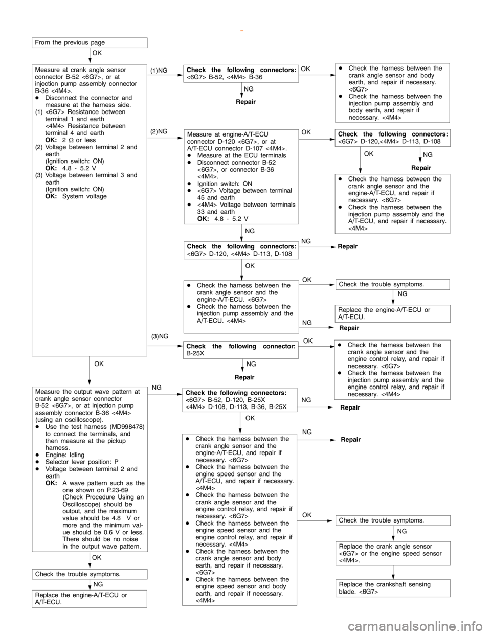
Page 921 of 1839
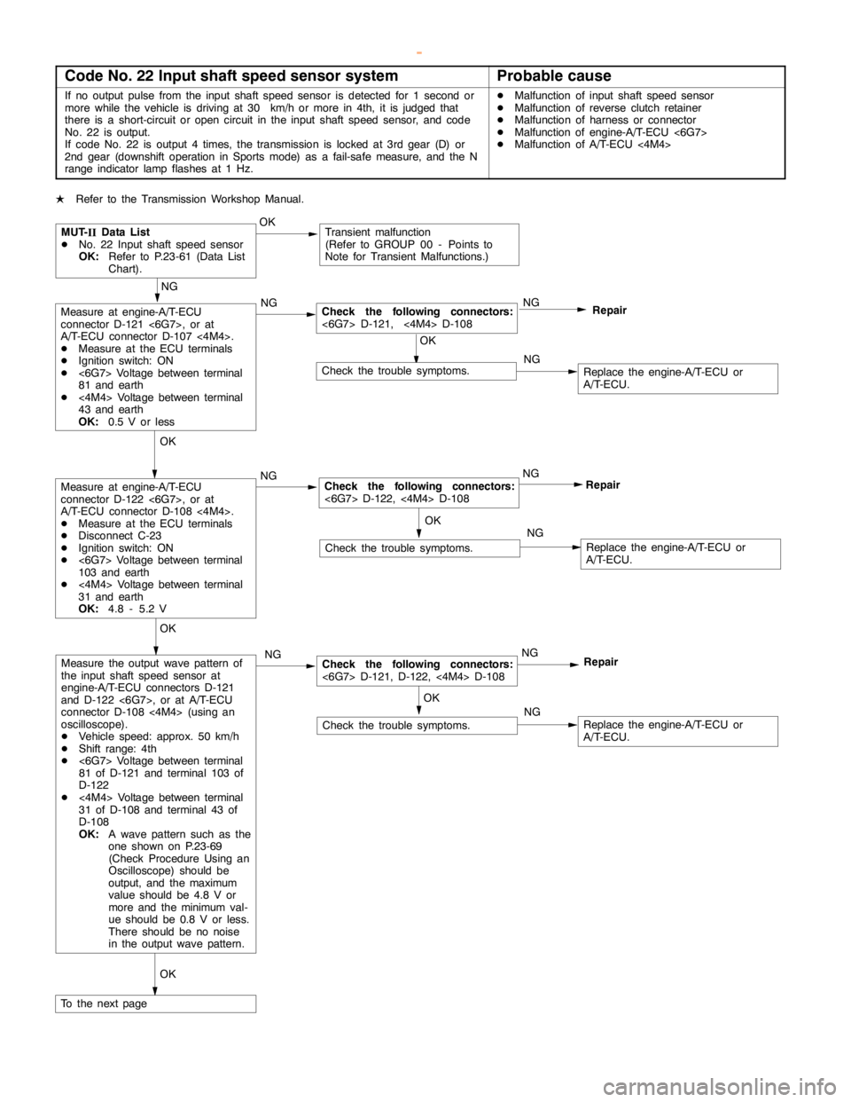
Page 922 of 1839
