2000 MITSUBISHI MONTERO check engine
[x] Cancel search: check enginePage 235 of 1839
GDI -Troubleshooting
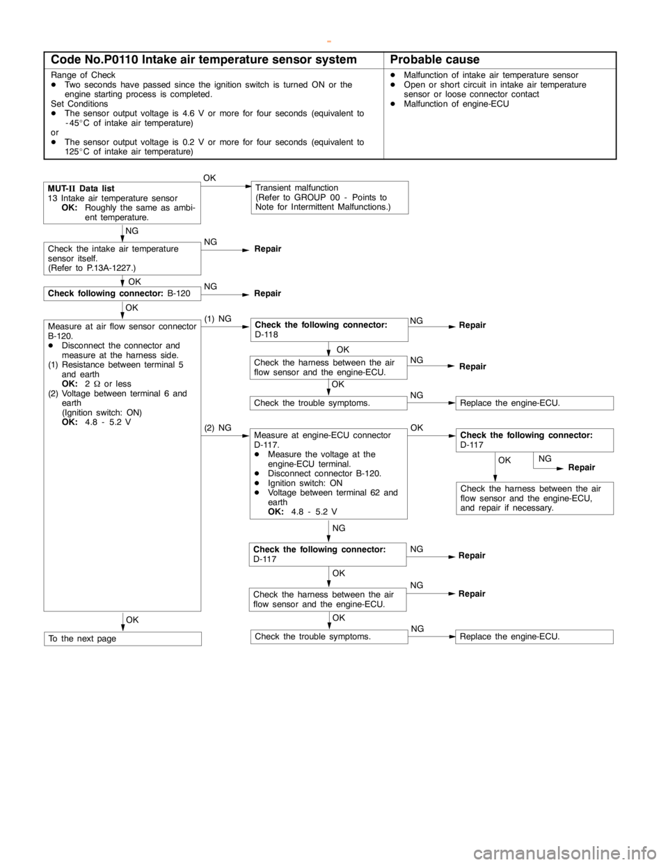
Code No.P0110 Intake air temperature sensor systemProbable cause
Range of Check
DTwo seconds have passed since the ignition switch is turned ON or the
engine startingprocess is completed.
Set Conditions
DThe sensor output voltage is 4.6 V or more for four seconds (equivalent to
-45_C of intake air temperature)
or
DThe sensor output voltage is 0.2 V or more for four seconds (equivalent to
125_C of intake air temperature)DMalfunction of intake air temperature sensor
DOpen or short circuit in intake air temperature
sensor or loose connector contact
DMalfunction of engine-ECU
OK
Check the harness between the air
flow sensor and the engine-ECU,
and repair if necessary.
MUT-
IIData list
13 Intake air temperature sensor
OK:
Roughly the same as ambi-
ent temperature.OKTransient malfunction
(Refer to GROUP 00 - Points to
Note for Intermittent Malfunctions.)
NG
Check the intake air temperature
sensor itself.
(Refer to P.13A-1227.)NG
Repair
OK
Measure at air flow sensor connector
B-120.
DDisconnect the connector and
measure at the harness side.
(1) Resistance between terminal 5
and earth
OK:
2Wor less
(2) Voltage between terminal 6 and
earth
(Ignition switch: ON)
OK:
4.8 - 5.2 V(1) NG
NGRepair
NG
Repair
NG
Check the following connector:
D-117NG
Repair
OK
Check the harness between the air
flow sensor and the engine-ECU.NG
Repair
OK
Check the trouble symptoms.NGReplace the engine-ECU.
OK
Check following connector:
B-120NG
Repair
(2) NGMeasure at engine-ECU connector
D-117.
DMeasure the voltage at the
engine-ECU terminal.
DDisconnect connector B-120.
DIgnition switch: ON
DVoltage between terminal 62 and
earth
OK:
4.8 - 5.2 VOKCheck the following connector:
D-117
OK
Check the harness between the air
flow sensor and the engine-ECU.NG
Repair
OK
Check the trouble symptoms.NGReplace the engine-ECU.
OK
To the nextpage
Check the following connector:
D-118
www.WorkshopManuals.co.uk
Purchased from www.WorkshopManuals.co.uk
Page 236 of 1839
GDI -Troubleshooting
OK
Measure at air flow sensor connector
B-120.
DUse the test harness (MB991709)
to connect only terminals 5 and
6, and then measure at the
pickup harness.
DIgnition switch: ON
DVoltage between terminal 6 and
earth
OK:
Ambient temperature 0_C:
3.2 - 3.8 V
Ambient temperature 20_C:
2.3 - 2.9 V
Ambient temperature 40_C:
1.5 - 2.1 V
Ambient temperature 80_C:
0.4 - 1.0 VNGCheck the following connectors:
D-117, D-118NG
Repair
OK
Check the harness between the air
flow sensor and the engine-ECU,
and repair if necessary.
OK
Check the trouble symptoms.NGReplace the engine-ECU.
From the previouspage
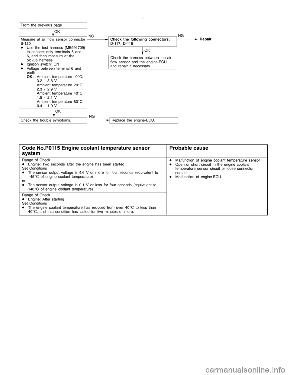
Code No.P0115 Engine coolant temperature sensor
systemProbable cause
Range of Check
DEngine: Two seconds after theengine has beenstarted
Set Conditions
DThe sensor output voltage is 4.6 V or more for four seconds (equivalent to
-45_C of engine coolant temperature)
or
DThe sensor output voltage is 0.1 V or less for four seconds (equivalent to
140_C of engine coolant temperature)DMalfunction of engine coolant temperaturesensor
DOpen or short circuit in theengine coolant
temperature sensor circuit or loose connector
contact
DMalfunction of engine-ECU
Range of Check
DEngine: After starting
Set Conditions
DThe engine coolant temperature has reduced fromover 40_C to less than
40_C, and that condition has lasted for five minutes or more.
www.WorkshopManuals.co.uk
Purchased from www.WorkshopManuals.co.uk
Page 237 of 1839
GDI -Troubleshooting
OK
Check the harness wire between the
engine coolant temperaturesensor
and the engine-ECU, and repair if
necesary.
MUT-
IIData list
21 Engine coolant temperature
sensor
OK:
When the engine iscold,
the temperature is roughly
the same asambient tem-
perature. If warm, it is 80 -
120_C.OKTransient malfunction
(Refer to GROUP 00 - Points to
Note for Intermittent Malfunctions.)
NG
NG
Replace
OK
Measure at engine coolant
temperature sensor connector B-56.
DDisconnect the connector and
measure at the harness side.
(1) Voltage between terminal 1 and
earth
(Ignition switch: ON)
OK:
4.8 - 5.2 V
(2) Resistance between terminal 2
and earth
OK:
2Wor less(1) NGMeasure at engine-ECU connector
D-117.
DMeasure the voltage at the
engine-ECU terminal.
DDisconnect connector B-56.
DIgnition switch: ON
DVoltage between terminal 44 and
earth
OK:
4.8 - 5.2 VOKCheck the following connector:
D-117
NG
Repair
NG
NG
Repair
OK
Check the trouble symptoms.NGReplace the engine-ECU.
OK
Check the following connector:
B-56NG
Repair
(2) NG
OKRepair
OK
Check the harness wire between the
engine coolant temperaturesensor
and the engine-ECU.NG
Repair
NG
Check the harness wire between the
engine coolant temperaturesensor
and the engine-ECU.NG
Repair
OK
Check the trouble symptoms.NGReplace the engine-ECU.
OK
To the nextpage
Measure at engine coolant
temperature sensor connector B-56.
DDisconnect the connector and
measure at the harness side.
DResistance between terminals 1
and 2
OK:
At 20_C of engine coolant
temperature: 2.1 - 2.7 kW
At 80_C of engine coolant
temperature: 0.26 - 0.36
kW
Check the following connector:
D-117
Check the following connector:
D-118
www.WorkshopManuals.co.uk
Purchased from www.WorkshopManuals.co.uk
Page 238 of 1839
GDI -Troubleshooting
OK
Measure at engine coolant
temperature sensor connector B-56.
DUse test harness (MB991658) to
connect the connector, and
measure at the pick-up harness.
DIgnition switch: ON
DVoltage between terminal 1 and
earth
OK:
At 0_C of engine coolant
temperature: 3.2 - 3.8 V
At 20_C of engine coolant
temperature: 2.3 - 2.9 V
At 40_C of engine coolant
temperature: 1.3 - 1.9 V
At 80_C of engine coolant
temperature] 0.3 - 0.9 VNGCheck theengine coolant
temperature sensor.
(Refer to P.13A-227.)NG
Repair
OK
Check the harness wire between the
engine coolant temperaturesensor
and the engine-ECU, and repair if
necessary.
OK
Check the trouble symptoms.NGReplace the engine-ECU.
OK
Check the following connectors:
D-117, D-118NG
Repair
From the previouspage
www.WorkshopManuals.co.uk
Purchased from www.WorkshopManuals.co.uk
Page 239 of 1839
GDI -Troubleshooting
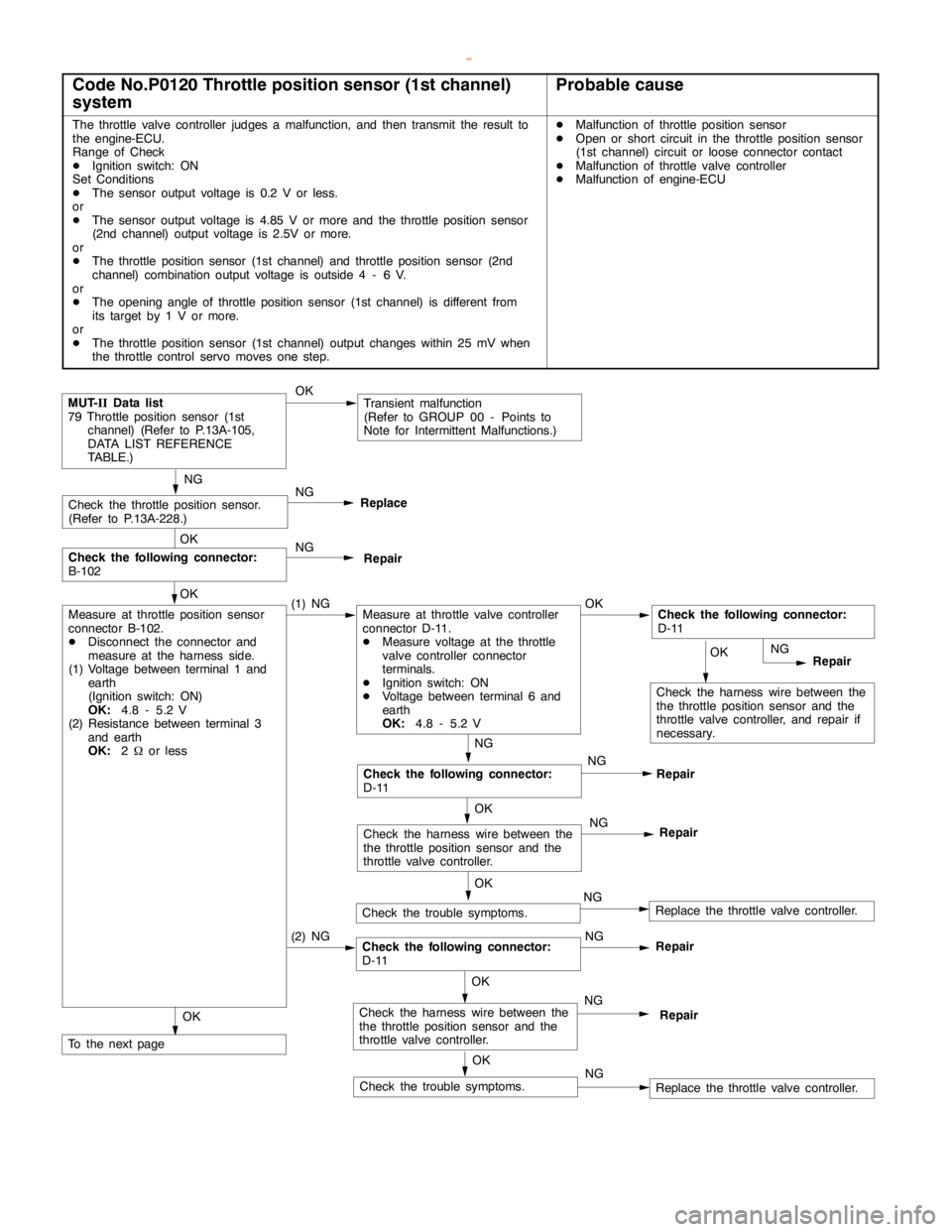
Code No.P0120 Throttle position sensor (1st channel)
systemProbable cause
The throttle valve controller judges a malfunction, and then transmit the result to
the engine-ECU.
Range of Check
DIgnition switch: ON
Set Conditions
DThe sensor output voltage is 0.2 V or less.
or
DThe sensor output voltage is 4.85 V or more and the throttle position sensor
(2nd channel) output voltage is 2.5V or more.
or
DThe throttle position sensor (1st channel) and throttle position sensor (2nd
channel) combination output voltage is outside 4 - 6 V.
or
DThe opening angle of throttle positionsensor (1st channel) is different from
its target by 1 V or more.
or
DThe throttle position sensor (1st channel) output changes within 25 mV when
the throttle control servo moves one step.DMalfunction of throttle position sensor
DOpen or short circuit in the throttle position sensor
(1st channel) circuit or loose connector contact
DMalfunction of throttle valve controller
DMalfunction of engine-ECU
OK
Check the harness wire between the
the throttle position sensor and the
throttle valve controller, and repair if
necessary.
MUT-
IIData list
79 Throttle position sensor (1st
channel) (Refer to P.13A-105,
DATA LIST REFERENCE
TABLE.)OKTransient malfunction
(Refer to GROUP 00 - Points to
Note for Intermittent Malfunctions.)
NG
Check the throttle position sensor.
(Refer to P.13A-228.)NG
Replace
OK
Measure at throttle position sensor
connector B-102.
DDisconnect the connector and
measure at the harness side.
(1) Voltage between terminal 1 and
earth
(Ignition switch: ON)
OK:
4.8 - 5.2 V
(2) Resistance between terminal 3
and earth
OK:
2Wor less(1) NGMeasure at throttle valve controller
connector D-11.
DMeasure voltage at the throttle
valve controller connector
terminals.
DIgnition switch: ON
DVoltage between terminal 6 and
earth
OK:
4.8 - 5.2 VOKCheck the following connector:
D-11
NG
Repair
NG
Check the following connector:
D-11NG
Repair
OK
Check the trouble symptoms.NGReplace the throttle valve controller.
OK
Check the following connector:
B-102NG
Repair
(2) NGCheck the following connector:
D-11NGRepair
OK
Check the harness wire between the
the throttle position sensor and the
throttle valve controller.NG
Repair
OK
Check the harness wire between the
the throttle position sensor and the
throttle valve controller.NG
Repair
OK
Check the trouble symptoms.NGReplace the throttle valve controller.
OK
To the nextpage
www.WorkshopManuals.co.uk
Purchased from www.WorkshopManuals.co.uk
Page 241 of 1839
GDI -Troubleshooting
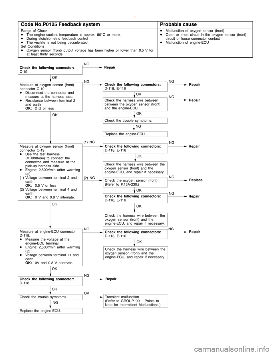
Code No.P0125 Feedback systemProbable cause
Range of Check
DThe engine coolant temperature is approx. 80_C or more.
DDuring stoichiometric feedback control
DThe vechile is notbeing deccelerated.
Set Conditions
DOxygen sensor (front) output voltage hasbeen higher orlower than 0.5 V for
at least thirty seconds.DMalfunction of oxygen sensor (front)
DOpen or short circuit in the oxygen sensor (front)
circuit or loose connector contact
DMalfunction of engine-ECU
Repair
OK
Measure at oxygen sensor (front)
connector C-19.
DDisconnect the connector and
measure at the harness side.
DResistance between terminal 2
and earth
OK:
2Wor lessNGCheck the following connectors:
D-118, E-116NG
OK
Check the trouble symptoms.
Check the following connector:
C-19NG
Repair
(2) NGCheck the oxygen sensor (front).
(Refer to P.13A-230.)NGReplace
OK
Check the harness wire between
between the oxygen sensor (front)
and the engine-ECU.NG
Repair
NG
Replace the engine-ECU.
Repair
OK
Measure at oxygen sensor (front)
connector C-19.
DUse the test harness
(MD998464) to connect the
connector, and measure at the
pick-up harness side.
DEngine: 2,500r/min (after warming
up)
(1) Voltage between terminal 2 and
earth
OK:
0.5 V or less
(2) Voltage between terminal 4 and
earth
OK:
0 V and 0.8 V alternate.(1) NGCheck the following connectors:
D-118, E-116NG
OK
Check the harness wire between the
oxygen sensor (front) and the
engine-ECU, and repair if necessary.
OK
NG
Repair
OK
Check the harness wire between the
oxygen sensor (front) and the
engine-ECU, and repair if necessary.
OK
NG
Check the following connectors:
D-118, E-116NG
OK
Check the harness wire between the
oxygen sensor (front) and the
engine-ECU, and repair if necessary.
OK
Check the following connector:
D-118
OKRepairNG
Check the trouble symptoms.OKTransient malfunction
(Refer to GROUP 00 - Points to
Note for Intermittent Malfunctions.)
NG
Replace the engine-ECU.
Repair
Check the following connectors:
D-118, E-116
Measure at engine-ECU connector
D-118.
DMeasure the voltage at the
engine-ECU terminal.
DEngine: 2,500r/min (after warming
up)
DVoltage between terminal 71 and
earth
OK:
0V and 0.8 V alternate.
www.WorkshopManuals.co.uk
Purchased from www.WorkshopManuals.co.uk
Page 242 of 1839

GDI -Troubleshooting
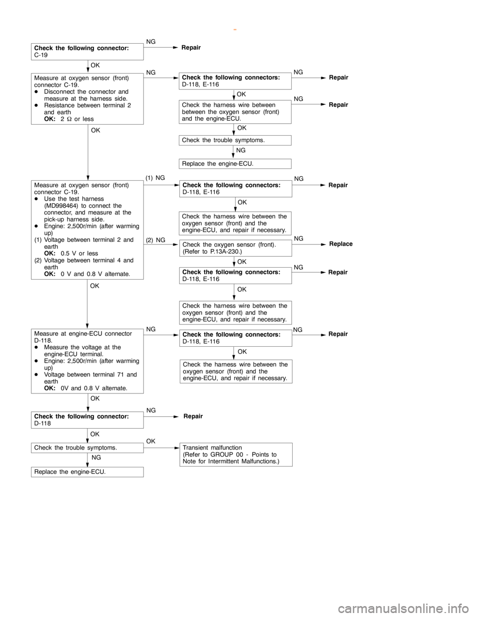
Code No.P0130 Oxygen sensor (front) system
Range of Check
DThree minutes havebeenpassed since theengine has been started.
DThe engine coolant temperature is approx. 80_C or more.
DIntake air temperature is 20 - 50_C
DEngine speed is 1,200 r/min or more
DDriving on a level surface at constant speed.
Set Conditions
DThe oxygen sensor (front) output voltage is 4.5 V or more when the sensor
output voltage is 0.2 V or less and a voltage of 5 V isapplied to theoxygen
sensor (front) inside the engine-ECU.DMalfunction of oxygen sensor (front)
DOpen or short circuit in the oxygen sensor (front)
circuit or loose connector contact
DMalfunction of engine-ECU
Range of Check
DEngine speed is 3,000 r/min or less
DDuring driving
DDuring air/fuel ratio feedback control
Set Conditions
DThe oxygen sensor (front) output frequency is five or less per 12 seconds on
average.
www.WorkshopManuals.co.uk
Purchased from www.WorkshopManuals.co.uk
Page 243 of 1839
GDI -Troubleshooting
Repair
OK
Measure at oxygen sensor (front)
connector C-19.
DDisconnect the connector and
measure at the harness side.
DResistance between terminal 2
and earth
OK:
2Wor lessNGCheck the following connectors:
D-118, E-116NG
OK
Check the trouble symptoms.
Check the following connector:
C-19NG
Repair
(2) NGCheck the oxygen sensor (front).
(Refer to P.13A-230.)NGReplace
OK
Check the harness wire between
between the oxygen sensor (front)
and the engine-ECU.NG
Repair
NG
Replace the engine-ECU.
Repair
OK
Measure at oxygen sensor (front)
connector C-19.
DUse the test harness
(MD998464) to connect the
connector, and measure at the
pick-up harness side.
DEngine: 2,500r/min (after warming
up)
(1) Voltage between terminal 2 and
earth
OK:
0.5 V or less
(2) Voltage between terminal 4 and
earth
OK:
0 V and 0.8 V alternate.(1) NGCheck the following connectors:
D-118, E-116NG
OK
Check the harness wire between the
oxygen sensor (front) and the
engine-ECU, and repair if necessary.
OK
NG
Repair
OK
Check the harness wire between the
oxygen sensor (front) and the
engine-ECU, and repair if necessary.
OK
NG
Check the following connectors:
D-118, E-116NG
OK
Check the harness wire between the
oxygen sensor (front) and the
engine-ECU, and repair if necessary.
OK
Check the following connector:
D-118
OKRepairNG
Check the trouble symptoms.OKTransient malfunction
(Refer to GROUP 00 - Points to
Note for Intermittent Malfunctions.)
NG
Replace the engine-ECU.
Repair
Check the following connectors:
D-118, E-116
Measure at engine-ECU connector
D-118.
DMeasure the voltage at the
engine-ECU terminal.
DEngine: 2,500r/min (after warming
up)
DVoltage between terminal 71 and
earth
OK:
0V and 0.8 V alternate.
www.WorkshopManuals.co.uk
Purchased from www.WorkshopManuals.co.uk