2000 MITSUBISHI MONTERO steering
[x] Cancel search: steeringPage 393 of 1839
Page 408 of 1839
Page 414 of 1839
Page 420 of 1839
Page 464 of 1839
15
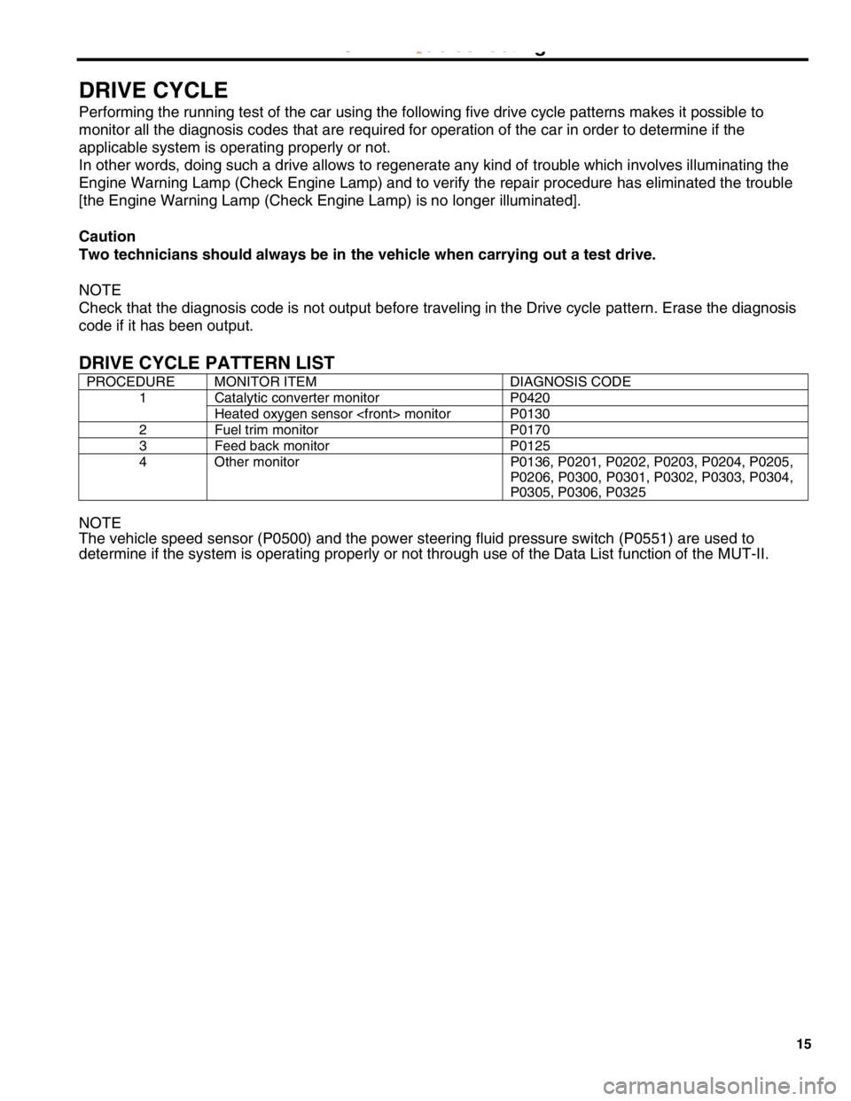
DRIVE CYCLE
Performing the running test of the car using the following five drive cycle patterns makes it possible to
monitor all the diagnosis codes that are required for operation of the car in order to determine if the
applicable system is operating properly or not.
In other words, doing such a drive allows to regenerate any kind of trouble which involves illuminating the
Engine Warning Lamp (Check Engine Lamp) and to verify the repair procedure has eliminated the trouble
[the Engine Warning Lamp (Check Engine Lamp) is no longer illuminated].
Caution
Two technicians should always be in the vehicle when carrying out a test drive.
NOTE
Check that the diagnosis code is not output before traveling in the Drive cycle pattern. Erase the diagnosis
code if it has been output.
DRIVE CYCLE PATTERN LIST
PROCEDURE MONITOR ITEM DIAGNOSIS CODE
Catalytic converter monitor P04201
Heated oxygen sensor
2 Fuel trim monitor P0170
3 Feed back monitor P0125
4 Other monitor P0136, P0201, P0202, P0203, P0204, P0205,
P0206, P0300, P0301, P0302, P0303, P0304,
P0305, P0306, P0325
NOTE
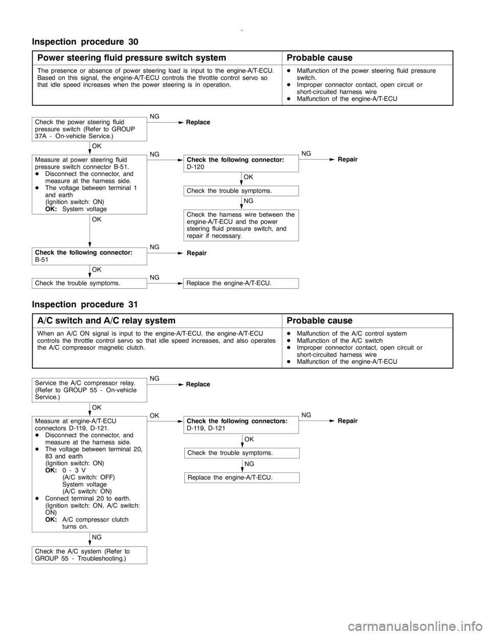
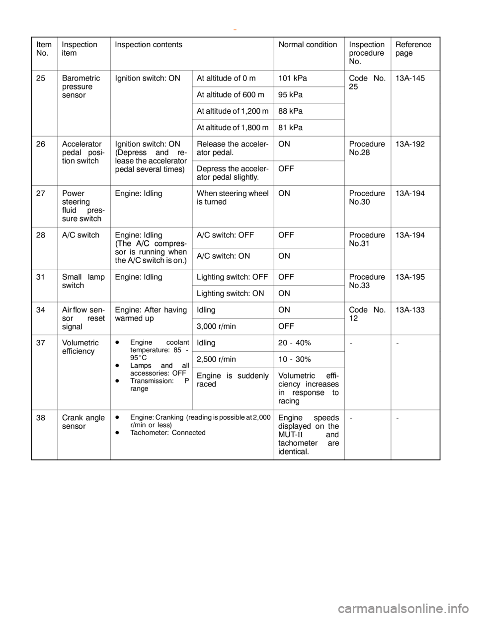
The vehicle speed sensor (P0500) and the power steering fluid pressure switch (P0551) are used to
determine if the system is operating properly or not through use of the Data List function of the MUT-II.
2001 PAJERO/MONTERO WAGON Workshop Manual 6G74
GDI - Troubleshooting
www.WorkshopManuals.co.uk
Purchased from www.WorkshopManuals.co.uk
Page 527 of 1839
DIESEL FUEL <4M4> -Troubleshooting13C-36
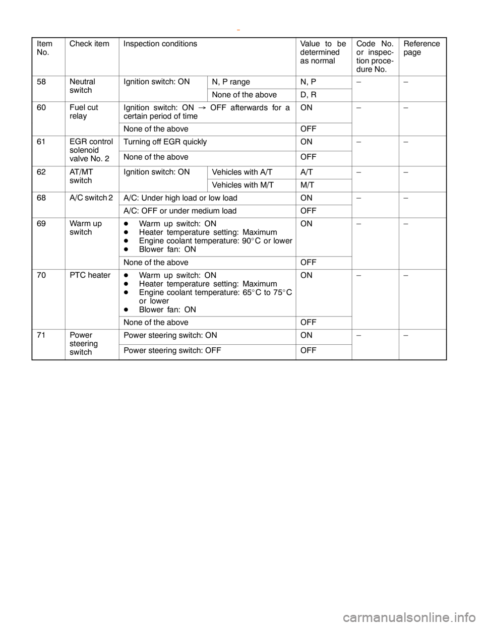
Item
No.Reference
page Code No.
or inspec-
tion proce-
dure No. Value to be
determined
as normal Inspection conditions Check item
58NeutralIgnition switch: ONN, P rangeN, P––
switchNone of the aboveD, R
60Fuel cut
relayIgnition switch: ON®OFF afterwards for a
certain period of timeON––
None of the aboveOFF
61EGR controlTurning off EGR quicklyON––
solenoid
valve No. 2None of the aboveOFF
62AT/MTIgnition switch: ONVehicles with A/TA/T––
switchVehicles with M/TM/T
68A/C switch 2A/C: Under high load or low loadON––
A/C: OFF or under medium loadOFF
69Warm up
switchDWarm up switch: ON
DHeater temperature setting: Maximum
DEngine coolant temperature: 90_C or lower
DBlower fan: ONON––
None of the aboveOFF
70PTC heaterDWarm up switch: ON
DHeater temperature setting: Maximum
DEngine coolant temperature: 65_Cto75_C
or lower
DBlower fan: ONON––
None of the aboveOFF
71PowerPower steering switch: ONON––
steering
switchPower steering switch: OFFOFF
www.WorkshopManuals.co.uk
Purchased from www.WorkshopManuals.co.uk
Page 1165 of 1839
POWER PLANT MOUNT - No.1 Crossmember32-7
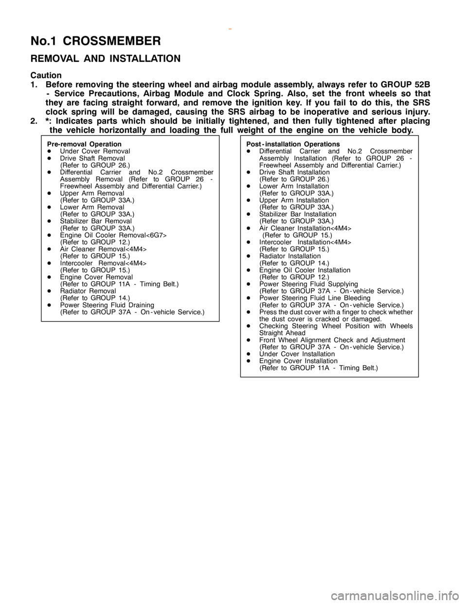
No.1 CROSSMEMBER
REMOVAL AND INSTALLATION
Caution
1. Before removing the steering wheel and airbag module assembly, always refer to GROUP 52B
- Service Precautions, Airbag Module and Clock Spring. Also, set the front wheels so that
they are facing straight forward, and remove the ignition key. If you fail to do this, the SRS
clock spring will be damaged, causing the SRS airbag to be inoperative and serious injury.
2. *: Indicates parts which should be initially tightened, and then fully tightened after placing
the vehicle horizontally and loading the full weight of the engine on the vehicle body.
Pre-removal Operation
DUnder Cover Removal
DDrive Shaft Removal
(Refer to GROUP 26.)
DDifferential Carrier and No.2 Crossmember
Assembly Removal (Refer to GROUP 26 -
Freewheel Assembly and Differential Carrier.)
DUpper Arm Removal
(Refer to GROUP 33A.)
DLower Arm Removal
(Refer to GROUP 33A.)
DStabilizer Bar Removal
(Refer to GROUP 33A.)
DEngine Oil Cooler Removal<6G7>
(Refer to GROUP 12.)
DAir Cleaner Removal<4M4>
(Refer to GROUP 15.)
DIntercooler Removal<4M4>
(Refer to GROUP 15.)
DEngine Cover Removal
(Refer to GROUP 11A - Timing Belt.)
DRadiator Removal
(Refer to GROUP 14.)
DPower Steering Fluid Draining
(Refer to GROUP 37A - On - vehicle Service.)Post - installation Operations
DDifferential Carrier and No.2 Crossmember
Assembly Installation (Refer to GROUP 26 -
Freewheel Assembly and Differential Carrier.)
DDrive Shaft Installation
(Refer to GROUP 26.)
DLower Arm Installation
(Refer to GROUP 33A.)
DUpper Arm Installation
(Refer to GROUP 33A.)
DStabilizer Bar Installation
(Refer to GROUP 33A.)
DAir Cleaner Installation<4M4>
(Refer to GROUP 15.)
DIntercooler Installation<4M4>
(Refer to GROUP 15.)
DRadiator Installation
(Refer to GROUP 14.)
DEngine Oil Cooler Installation
(Refer to GROUP 12.)
DPower Steering Fluid Supplying
(Refer to GROUP 37A - On - vehicle Service.)
DPower Steering Fluid Line Bleeding
(Refer to GROUP 37A - On - vehicle Service.)
DPress the dust cover with a finger tocheck whether
the dust cover is cracked or damaged.
DChecking Steering Wheel Position with Wheels
StraightAhead
DFront Wheel AlignmentCheck and Adjustment
(Refer to GROUP 37A - On - vehicle Service.)
DUnder Cover Installation
DEngine Cover Installation
(Refer to GROUP 11A - Timing Belt.)
www.WorkshopManuals.co.uk
Purchased from www.WorkshopManuals.co.uk
Page 1265 of 1839
ABS <4WD> -General Information35B-2
GENERAL INFORMATION
ABS has been adopted as standard equipment
in all vehicles to maintain directional stability and
steering performance during sudden braking.
The ABS control method used is a 4-sensor,
4-channel method (previous models: 4-sensor,
3- channel method
)which allows the brake
pressures for all four wheels to be controlled
independently of each other. The system has the
following features.
DEBD
*(Electronic Brake force Distribution
system) control has been added to provide the
ideal braking force for the rear wheels.DThe hydraulic unit function has been integrated
with the hydraulic brake booster (HBB).
DSelect solenoid valves (two valves for FL and
FR) have been adopted in order to reduce the
pedal kickback and improve the operation
feeling when the ABS is operating.
DIndependent 4-wheel control is carried out wile
the vehicle is turning in order to increase the
braking force.
NOTE
*EBD: Electronic Brake-force Distribution
EBD CONTROL
In ABS, electronic control method is used whereby
the rear wheel brake hydraulic pressure during
braking is regulated by rear wheel control solenoid
valves in accordance with the vehicle’s rate of
deceleration and the front and rear wheel slippage
which are calculated from the signals received from
the various wheel sensors. EBD control is a control
system which provides a high level of control for
both vehicle braking force and vehicle stability. The
system has the following features.
DBecause the system provides the optimum rear
wheel braking force regardless of the vehicle
laden condition and the condition of the road
surface, the system reduces the required pedal
depression force, particularly when the vehicle
is heavily laden or driving on road surfaces
with high frictional coefficients.DBecause the duty placed on the front brakes
has been reduced, the increases in pad
temperature can be controlled during front
brakes applying to improve the wear resistance
characteristics of the pad.
DControl valves such as the proportioning valve
are no longer required.
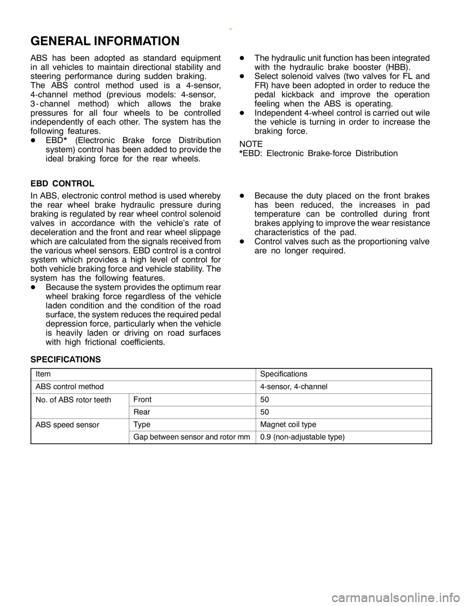
SPECIFICATIONS
ItemSpecifications
ABS control method4-sensor, 4-channel
No. of ABS rotor teethFront50
Rear50
ABS speed sensorTypeMagnet coil type
Gap between sensor and rotor mm0.9 (non-adjustable type)
www.WorkshopManuals.co.uk
Purchased from www.WorkshopManuals.co.uk