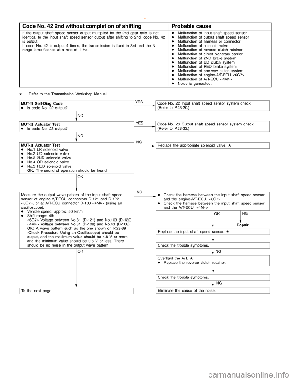
2000 MITSUBISHI MONTERO brake sensor
[x] Cancel search: brake sensorPage 814 of 1839
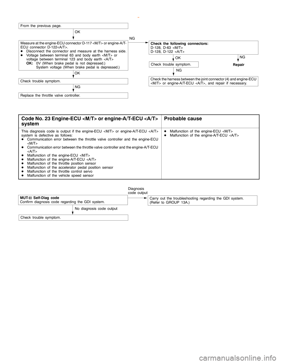
ENGINE AND EMISSION CONTROL -Auto-cruise Control System17-12
NG
Check the harness between the joint connector (4) and engine-ECU
NG
Repair
OK
Check trouble symptom.
From the previous page.
OK
Check the following connectors:
D-128, D-63
D-128, D-122
OK
Check trouble symptom.
NG
Replace the throttle valve controller.NG
Measure at the engine-ECU connector D-117
ECU connector D-122.
DDisconnect the connector and measure at the harness side.
DVoltage between terminal 63 and body earth
voltage between terminal 123 and body earth
OK:0V (When brakepedal is not depressed.)
System voltage (When brakepedal is depressed.)
Code No. 23 Engine-ECU
systemProbable cause
This diagnosis code is output if the engine-ECU
system is defective as follows:
DCommunication error between the throttle valve controller and the engine-ECU
DCommunication error between the throttle valve controller and the engine-A/T-ECU
DMalfunction of the engine-ECU
DMalfunction of the engine-A/T-ECU
DMalfunction of the throttle position sensor
DMalfunction of the accelerator pedal positionsensor
DMalfunction of the throttle control servo
DMalfunction of the vehicle speed sensorDMalfunction of the engine-ECU
DMalfunction of the engine-A/T-ECU
MUT-
IISelf-Diag code
Confirm diagnosis code regarding the GDI system.Diagnosis
code outputCarry out the troubleshooting regarding the GDI system.
(Refer to GROUP 13A.)
No diagnosis code output
Check trouble symptom.
www.WorkshopManuals.co.uk
Purchased from www.WorkshopManuals.co.uk
Page 816 of 1839
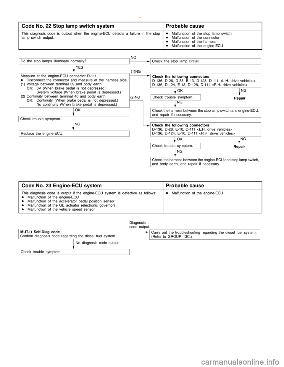
ENGINE AND EMISSION CONTROL -Auto-cruise Control System17-14
Code No. 22 Stop lamp switch systemProbable cause
This diagnosis code is output when the engine-ECU detects a failure in the stop
lampswitch output.DMalfunction of the stoplampswitch
DMalfunction of the connector
DMalfunction of the harness
DMalfunction of the engine-ECU
(2)NG
NG
Check the harness between the engine-ECU and stoplampswitch,
and body earth, and repair if necessary.
NG
Repair
OK
Check trouble symptom.
Measure at the engine-ECU connector D-111.
DDisconnect the connector and measure at the harness side.
(1) Voltage between terminal 39 and body earth
OK:0V (When brakepedal is not depressed.)
System voltage (When brakepedal is depressed.)
(2) Continuity between terminal 40 and body earth
OK:Continuity (When brakepedal is not depressed.)
No continuity (When brakepedal is depressed.)NO
Do the stop lamps illuminate normally?
OK
Check trouble symptom.
Check the following connectors:
D-136, D-26, D-33, E-13, D-128, D-111
D-136, D-124, E-13, D-128, D-111
OK
Check trouble symptom.
NG
Check the harness between the stoplampswitch and engine-ECU,
and repair if necessary.NG
Repair
Check the stoplampcircuit.
YES
(1)NG
Check the following connectors:
D-136, D-26, E-10, D-111
D-136, D-124, E-10, D-111
Replace the engine-ECU.
Code No. 23 Engine-ECU systemProbable cause
This diagnosis code is output if the engine-ECU system is defective as follows:
DMalfunction of the engine-ECU
DMalfunction of the accelerator pedal positionsensor
DMalfunction of the GE actuator (electronic governor)
DMalfunction of the vehicle speed sensorDMalfunction of the engine-ECU
MUT-
IISelf-Diag code
Confirm diagnosis code regarding the diesel fuel system.Diagnosis
code outputCarry out the troubleshooting regarding the diesel fuel system.
(Refer to GROUP 13C.)
No diagnosis code output
Check trouble symptom.
www.WorkshopManuals.co.uk
Purchased from www.WorkshopManuals.co.uk
Page 827 of 1839

ENGINE AND EMISSION CONTROL -Auto-cruise Control System17-25
DATA LIST REFERENCE TABLE
For the data, which is input to the engine-ECU
<6G7-M/T, 4M4>, engine-A/T-ECU <6G7-A/T> andthrottle valve controller <6G7>, the following items
can be read out by using the MUT-II
.
HOW TO READ OUT DATA LIST
1. Connect the MUT-II
to the 16-pin diagnosis
connector.
Caution
Turn off the ignition switch befor connecting
and disconnecting the MUT-II
.2. Turn the ignition switch to “ON” position.
3. Select “auto-cruise control” on the MUT-II
menu, and then read out the data list.
<6G7>
Terminal
No.Check itemCheck conditionsNormal condition
01Auto-cruiseMAINMAIN switch: ONON
control
switchMAIN switch: OFFOFF
02SETMAIN switch:SET switch: ONON
(COAST)ONSET switch: OFFOFF
03RESUMERESUME switch: ONON
(ACCEL)RESUME switch: OFFOFF
04CANCELCANCEL switch: ONON
CANCEL switch: OFFOFF
05Stop lamp switchBrake pedal: DepressedON
(for stop lamp circuit)Brake pedal: ReleasedOFF
06Stop lamp switchBrake pedal: DepressedOFF
(for auto-cruise control
circuit)
Brake pedal: ReleasedON
07Clutch switch
Brake pedal: ReleasedOFF
Inhibitor switchSelector lever: “N“, “P” positionON
Selector lever: Other than “N“, “P” positionOFF
08Accelerator switchAccelerator pedal: ReleasedON
(Idle position switch)Accelerator pedal: DepressedOFF
09Auto-cruise controlAuto-cruise control system: ActivatedON
systemAuto-cruise control system: Not activatedOFF
10Vehicle speed sensorRoad test the vehicleThe speedometer and
the MUT-IIdisplay the
same value.
www.WorkshopManuals.co.uk
Purchased from www.WorkshopManuals.co.uk
Page 828 of 1839

ENGINE AND EMISSION CONTROL -Auto-cruise Control System17-26
Terminal
No.Normal condition Check conditions Check item
11Throttle position sensorAccelerator pedal: Fully depressed450 - 800 mV
Accelerator pedal: DepressedThe more deeply the
pedal is depressed, the
higher value the MUT-
IIdisplay
Accelerator pedal: Release4,200 - 4,900 mV
12Accelerator pedalAccelerator pedal: Fully depressed985 - 1,085 mV
position sensorAccelerator pedal: DepressedThe more deeply the
pedal is depressed, the
higher value the MUT-
IIdisplay
Accelerator pedal: Release4,000 mV or more
<4M4>
Terminal
No.Check itemCheck conditionsNormal condition
01Auto-cruiseMAINMAIN switch: ONON
control
switchMAIN switch: OFFOFF
02SETMAIN switch:SET switch: ONON
(COAST)ONSET switch: OFFOFF
03RESUMERESUME switch: ONON
(ACCEL)RESUME switch: OFFOFF
04CANCELCANCEL switch: ONON
CANCEL switch: OFFOFF
05Stop lamp switchBrake pedal: DepressedON
(for stop lamp circuit)Brake pedal: ReleasedOFF
06Stop lamp switchBrake pedal: DepressedOFF
(for auto-cruise control
circuit)
Brake pedal: ReleasedON
07Clutch switch
Brake pedal: ReleasedOFF
Inhibitor switchSelector lever: “N”, “P” positionON
Selector lever: Other than “N”, “P” positionOFF
08Accelerator switchAccelerator pedal: ReleasedON
(Idle position switch)Accelerator pedal: DepressedOFF
09Auto-cruise controlAuto-cruise control system: ActivatedON
systemAuto-cruise control system: Not activatedOFF
www.WorkshopManuals.co.uk
Purchased from www.WorkshopManuals.co.uk
Page 907 of 1839

Page 933 of 1839
Page 934 of 1839
Page 935 of 1839
