2000 MITSUBISHI MONTERO coolant
[x] Cancel search: coolantPage 679 of 1839

ENGINE COOLING -General Information/
Service Specifications/Lubricant/Sealant14-2
GENERAL INFORMATION
The cooling system is designed to keep every part
of the engine at appropriate temperature in
whatever condition the engine may be operated.
The cooling method is of the water-cooled, pressure
forced circulation type in which the water pump
pressurizes coolant and circulates it throughout the
engine. If the coolant temperature exceeds the
prescribed temperature, the thermostat opens to
circulate the coolant through the radiator as well
so that the heat absorbed by the coolant may be
radiated into the air.The water pump is of the centrifugal type and is
driven by the drive belt from the crankshaft.
The radiator is the corrugated fin, down flow type.
ItemsSpecifications
RadiatorPerformance kJ/h6G7203,023
4D5, 4M4232,326
SERVICE SPECIFICATIONS
ItemsStandard valueLimit
High pressure valve opening pressure of radiator cap kPa74 - 10364
Range of coolant antifreeze concentration of radiator %30 - 60-
ThermostatValve opening temper-6G788±
2.0-
ature of thermostat_
C4D582±
1.5-
4M476.5±
2.0-
Full-opening tempera-6G7100-
ture of thermostat_
C4D595-
4M490-
Valve lift mm6G710 or more-
4D5, 4M48.5 or more-
LUBRICANT
ItemApplicable modelAmount (including
condense tank) L
MITSUBISHI GENUINE COOLANT or equivalentVehicles without rear heater9.0
Vehicles with rear heater10.5
SEALANT
ItemsSpecified sealantRemarks
Cylinder block drain plug3M Nut Locking Part No. 4171 or equivalentDrying sealant
www.WorkshopManuals.co.uk
Purchased from www.WorkshopManuals.co.uk
Page 749 of 1839

16-1
ENGINE
ELECTRICAL
CONTENTS
CHARGING SYSTEM 2................
GENERAL INFORMATION 2................
SERVICE SPECIFICATIONS 3..............
SPECIAL TOOL 4.........................
ON-VEHICLE SERVICE 5..................
Alternator Output Line Voltage Drop Test 5....
Output Current Test 6.......................
Regulated Voltage Test 8....................
Waveform Check Using An Analyzer 11.......
ALTERNATOR 13.........................
STARTING SYSTEM 23................
GENERAL INFORMATION 23..............
SERVICE SPECIFICATIONS 24............
STARTER MOTOR 24.....................
IGNITION SYSTEM 37.................
GENERAL INFORMATION 37..............
SERVICE SPECIFICATIONS 38............
SPECIAL TOOL 38.......................
ON-VEHICLE SERVICE 38................
Ignition Coil (With Built-in Power Transistor)
Check 38...................................
Spark Plug Check and Cleaning 39...........
Ignition Failure Sensor Check 40.............
Camshaft Position Sensor Check, Crank angle
Sensor Check, Detonation Sensor Check 40...
IGNITION COIL <6G7> 41.................
CRANKSHAFT ANGLE SENSOR
<6G7> 42................................
CAMSHAFT POSITION SENSOR
<6G7> 42................................
DETONATION SENSOR <6G7> 43.........
GLOW SYSTEM 44....................
GENERAL INFORMATION 44..............
SERVICE SPECIFICATIONS 45............
ON-VEHICLE SERVICE 45................
Self-regulating Glow System Check 45........
Glow & EGR Control Unit Check 48..........
Engine ECU Check 49.......................
Glow Plug Relay Check 50..................
Glow Plug Check 51........................
Engine Coolant Temperature Sensor
Check 51...................................
GLOW PLUG 52..........................
www.WorkshopManuals.co.uk
Purchased from www.WorkshopManuals.co.uk
Page 804 of 1839

17-2
EVAPORATIVE EMISSION CONTROL
SYSTEM 36..............................
General Information 36......................
System Diagram 36.........................
Component Location 36......................
Purge Control System Check 37..............
Purge Port Vacuum Check 37................
Purge Control Solenoid Valve Check 38.......
EXHAUST GAS RECIRCULATION (EGR)
SYSTEM 39..............................
General Information 39......................
Operation 39................................
System Diagram 39.........................
Component Location 39......................
Exhaust Gas Recirculation (EGR) Control
System Check 40...........................
EGR Valve (Stepper Motor) Check 40........
EGR VALVE 42...........................
CANISTER 43............................
CATALYTIC CONVERTER 44..............
General Information 44......................
EMISSION CONTROL SYSTEM
<4D5> 45.............................
GENERAL INFORMATION 45..............
SERVICE SPECIFICATIONS 45............
SEALANT 45.............................
SPECIAL TOOL 45.......................
EXHAUST GAS RECIRCULATION (EGR)
SYSTEM 46..............................
General Information 46......................
System Diagram 46.........................
Component Location 46......................
Function Check 47..........................
EGR Solenoid Valve Operation Check 47.....
EGR Solenoid Valve Resistance Check 48....
Lever Position Sensor (LPS) Adjustment 48...
Engine Speed Sensor Check 49..............
Engine Coolant Temperature Sensor
Check 49...................................
CHECK AT THE GLOW & EGR CONTROL
UNIT 51..................................
EMISSION CONTROL SYSTEM
<4M4-VEHICLES WITH EGR> 52........
GENERAL INFORMATION 52..............
SERVICE SPECIFICATIONS 52............
EXHAUST GAS RECIRCULATION (EGR)
SYSTEM 53..............................
General Information 53......................
System Diagram 53.........................
Component Location 53......................
Function Check 54..........................
EGR Solenoid Valve Operation Check 54.....
EGR Solenoid Valve Resistance Check 55....
Accelerator Pedal Position Sensor (APS),
Engine Coolant Temperature Sensor, Intake
Air Temperature Sensor, Fuel Temperature
Sensor Check 55............................
Check at Engine-ECU 55....................
CATALYTIC CONVERTER 55..............
General Information 55......................
www.WorkshopManuals.co.uk
Purchased from www.WorkshopManuals.co.uk
Page 958 of 1839

Page 1572 of 1839

54A-2
CHASSIS
ELECTRICAL
CONTENTS
BATTERY 4
..............................
SERVICE SPECIFICATIONS 4..................
ON-VEHICLE SERVICE 4......................
Electrolyte Level and Specific Gravity Check 4..
Charging 5.................................
Battery Test 5...............................
IGNITION SWITCH AND IMMOBILIZER
SPECIAL TOOLS 6............................
TROUBLESHOOTING 6........................
IGNITION SWITCH AND
IMMOBILIZER-ECU 11.........................
IGNITION SWITCH AND IMMOBILIZER
<4D56> 14...............................
SPECIAL TOOLS 14...........................
TROUBLESHOOTING 14.......................
IGNITION SWITCH AND IMMOBILIZER-ECU
19 ............................................
COMBINATION METER 23................
SERVICE SPECIFICATIONS 23.................
SEALANTS 24................................
SPECIAL TOOLS 24...........................
TROUBLESHOOTING 24.......................
ON-VEHICLE SERVICE 30.....................
Speedometer Check 30......................
Tachometer Check 30........................
Fuel Gauge Unit Check 31....................Engine Coolant Temperature Gauge Unit Check
32 .........................................
COMBINATION METER 33.....................
HEADLAMP ASSEMBLY 36...............
SERVICE SPECIFICATIONS 36.................
SPECIAL TOOLS 36...........................
TROUBLESHOOTING 36.......................
ON-VEHICLE SERVICE 36.....................
Headlamp Aiming Adjustment 36..............
Luminance Measurement 38..................
Headlamp Bulb Replacement 39...............
HEADLAMP ASSEMBLY 40....................
FOG LAMPS 41..........................
SERVICE SPECIFICATIONS 41.................
SPECIAL TOOLS 41...........................
TROUBLESHOOTING 41.......................
ON-VEHICLE SERVICE 41.....................
Fog Lamp Aiming Check 41...................
FOG LAMPS 44...............................
SIDE TURN-SIGNAL LAMPS 45...........
SPECIAL TOOLS 45...........................
SIDE TURN-SIGNAL LAMPS 46................
ROOM LAMP 46.........................
TROUBLESHOOTING 46.......................
CONTINUED ON NEXT PAGE
www.WorkshopManuals.co.uk
Purchased from www.WorkshopManuals.co.uk
Page 1593 of 1839

CHASSIS ELECTRICAL-Combination Meter54A-23
COMBINATION METER
SERVICE SPECIFICATIONS
ItemStandard valueLimit
Speedometer indication rangeAt 20 km/h18 - 23–
km/hAt 40 km/h37 - 45–
At 80 km/h75 - 88–
At 120 km/h113 - 132–
At 160 km/h150 - 176–
Speedometer needle swing km/h (when driving at 35 km/h or higher)–±3
Tachometer indication errorWhen engine speed is 700 r/min±120–
r/minWhen engine speed is 2,000 r/minPetrol- 175+225–
Diesel±175–
When engine speed is 3,000 r/minPetrol- 175+300–
Diesel±225–
When engine speed is 4,000 r/minPetrol- 225+375–
Diesel±300–
When engine speed is 4,750 r/min
When engine speed is 5,000 r/min
When engine speed is 6,000 r/min
Fuel gauge unit standardF position3–
resistance valueWE position11 0–
Fuel gauge unit float heightF position11.9–
mmE position195.2–
Engine coolant temperature gauge unit standard resistance valueW104±13.5–
Combination meter internal62 - 11 (IG power supply - earth)1MWor more–
resistance valueW62 - 25 (IG power supply - earth)1MWor more–(Measured at connector D-38
and connector D-40)
62 - 63 (IG power supply - fuel gauge)1MWor more–
62 - 64 (IG power supply - engine coolant
temperature gauge)1MWor more–
63 - 11 (fuel gauge - earth)180–
63 - 25 (fuel gauge - earth)180–
64 - 11 (engine coolant temperature gauge - earth)210–
64 - 25 (engine coolant temperature gauge - earth)210–
67 - 11 (battery power supply - earth)1MWor more–
67 - 25 (battery power supply - earth)1MWor more–
67 - 63 (battery power supply - fuel gauge)1MWor more–
67 - 64 (battery power supply - engine coolant
temperature gauge)1MWor more–
www.WorkshopManuals.co.uk
Purchased from www.WorkshopManuals.co.uk
Page 1595 of 1839

CHASSIS ELECTRICAL-Combination Meter CHASSIS ELECTRICAL-Combination Meter54A-25
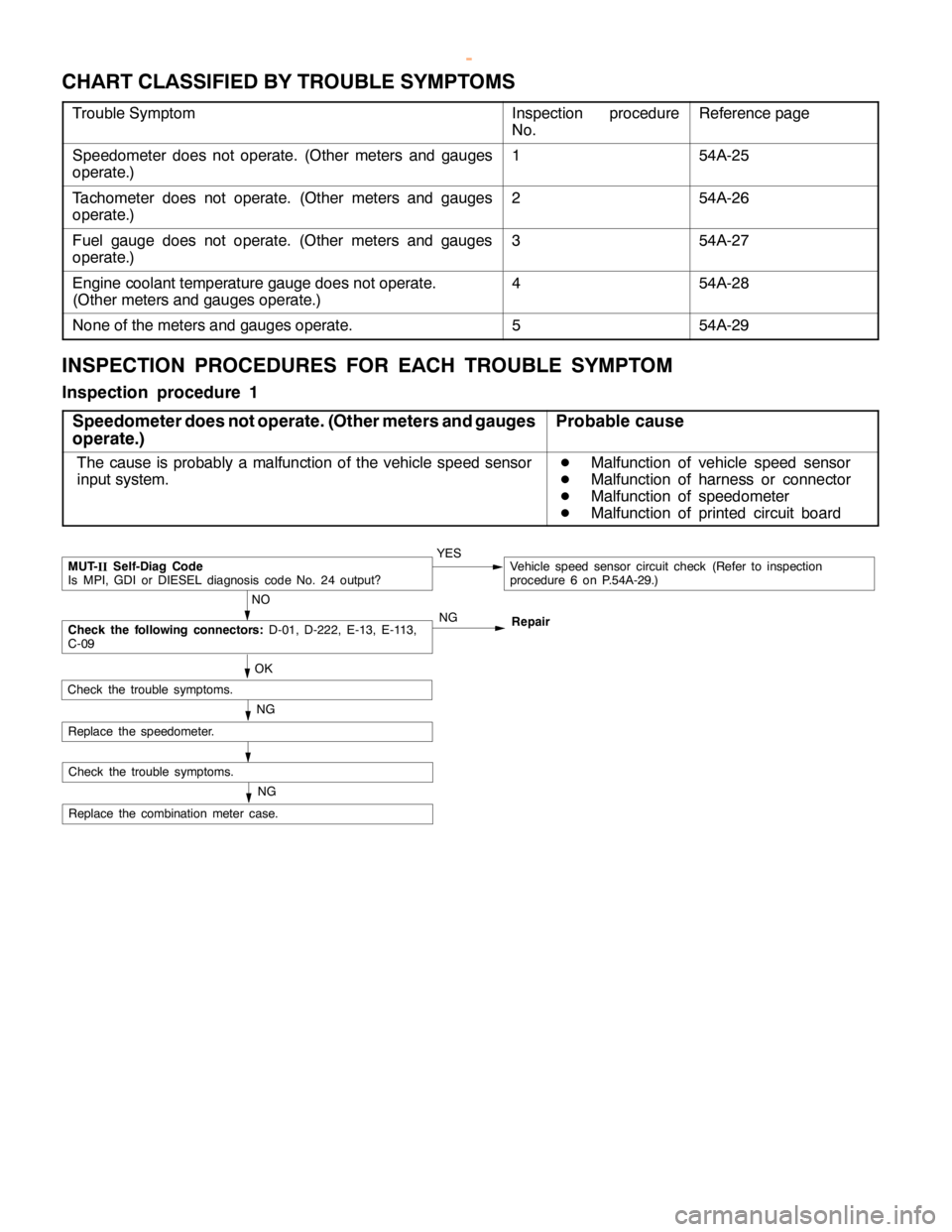
CHART CLASSIFIED BY TROUBLE SYMPTOMS
Trouble SymptomInspection procedure
No.Reference page
Speedometer does not operate. (Other meters and gauges
operate.)154A-25
Tachometer does not operate. (Other meters and gauges
operate.)254A-26
Fuel gauge does not operate. (Other meters and gauges
operate.)354A-27
Engine coolant temperature gauge does not operate.
(Other meters and gauges operate.)454A-28
None of the meters and gauges operate.554A-29
INSPECTION PROCEDURES FOR EACH TROUBLE SYMPTOM
Inspection procedure 1
Speedometer does not operate. (Other meters and gauges
operate.)
Probable cause
The cause is probably a malfunction of the vehicle speed sensor
input system.D
Malfunction of vehicle speed sensor
D
Malfunction of harness or connector
D
Malfunction of speedometer
D
Malfunction of printed circuit board
NO
MUT-
IISelf-Diag Code
Is MPI, GDI or DIESEL diagnosis code No. 24 output?YESVehicle speed sensor circuit check (Refer to inspection
procedure 6 on P.54A-29.)
OK
Replace the combination meter case.
NG
Check the trouble symptoms.
NGCheck the following connectors:D-01, D-222, E-13, E-113,
C-09Repair
NG
Check the trouble symptoms.
Replace the speedometer.
www.WorkshopManuals.co.uk
Purchased from www.WorkshopManuals.co.uk
Page 1748 of 1839

55A-2
HEATER, AIR
CONDITIONER AND
VENTILATION
CONTENTS
SERVICE SPECIFICATIONS 3.................
LUBRICANTS 3..............................
TROUBLESHOOTING
TROUBLESHOOTING
ON-VEHICLE SERVICE 9.....................
Refrigerant Level Test through Performance Test 9.
Magnetic Clutch Test 10.........................
Receiver Drier Test 10..........................
Compressor Drive Belt Adjustment 10.............
Dual Pressure Switch Check 10..................
Charging 11...................................
Performance Test 15............................
Front Blower Relay and Rear Blower Relay
Continuity Check 18............................
Continuity Check of A/C Compressor Relay and
Condernser Fan Relay 18.......................
PTC Heater Relay Continuity Check 19...........
Idle-up Operation Check
Vacuum Actuator Check
Idle-up Solenoid Valve Check 21.................
Clean Air Filter Replacement Procedure 22........
FRONT A/C 23..............................
Air Conditioner Control Panel Assembly and
A/C Switch 23.................................
Heater Unit and Blower Assembly 26.............
Blower Motor and Resistor 29....................
Inside/Outside Air Changeover Damper Motor 30...
Automatic Compressor-ECU and
Air Thermo Sensor Assembly 31.................
REAR HEATER AND REAR COOLER 32.....
Rear A/C Switch, Front Rear Fan Switch 32.......
Rear A/C Control Unit 34........................
Rear Heater Unit 34............................
Rear Heater Unit and Rear Blower Assembly 37....
HEAT SWITCH 40...........................
COMPRESSOR 41...........................
CONDENSER ASSEMBLY AND
CONDENSER FAN 45........................
REFRIGERANT LINE 47.....................
ENGINE COOLANT TEMPERATURE SWITCH
51 ..........................................
IDLE-UP SYSTEM 53........................
DUCTS 54..................................
VENTILATION 56............................
www.WorkshopManuals.co.uk
Purchased from www.WorkshopManuals.co.uk