Page 1631 of 1839
CHASSIS ELECTRICAL -Clock or Center Display54A-61
INSPECTION CHART CLASSIFIED BY TROUBLE SYMPTOMS
Related unitTrouble SymptomInspection pro-
cedure No.Reference
page
Malfunction of center
display, related sen-No display appears after the ignition key is turned to the
ACC position.154A-62
sors, and wiring har-
nesses
Outside air temperature does not appear or abnormal
outside air temperature appears.254A-62
Abnormal vehicle speed is displayed on the service
mode.354A-63
Abnormal driving data are displayed:
D
Abnormal average fuel consumption (momentary
fuel consumption) and average vehicle speed
D
Abnormal cruising distance454A-64
Clock runs fast or slow.554A-64
The display screen is dim.654A-65
Air conditioning display does not apper.754A-66
www.WorkshopManuals.co.uk
Purchased from www.WorkshopManuals.co.uk
Page 1632 of 1839
CHASSIS ELECTRICAL -Clock or Center Display54A-62
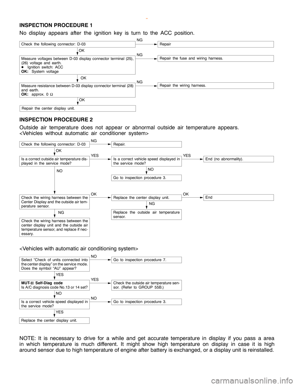
INSPECTION PROCEDURE 1
No display appears after the ignition key is turn to the ACC position.
OK
Measure voltages between D-03 display connector terminal (25),
(26) voltage and earth.
DIgnition switch: ACC
OK:System voltageNGRepair the fuse and wiring harness.
OK
Measure resistance between D-03 display connector terminal (28)
and earth.
OK:approx. 0
WNGRepair the wiring harness.
OK
Repair the center display unit.
Check the following connector: D-03NGRepair
INSPECTION PROCEDURE 2
Outside air temperature does not appear or abnormal outside air temperature appears.
Check the following connector: D-03NGRepair.
NO
Go to inspection procedure 3.
Check the wiring harness between the
Center Display and the outside air tem-
perature sensor.OKReplace the center display unit.OKEnd
NG
Replace the outside air temperature
sensor.NG
Check the wiring harness between the
center display unit and the outside air
temperature sensor, and replace if nec-
essary.
OK
Is a correct outside air temperature dis-
played in the servicemode?YESIs a correct vehicle speed displayed in
the servicemode?YESEnd (no abnormality).
NO
Select “Check of units connected into
the center display” on the service mode.
Does the symbol “AU” appear?NOGo to inspection procedure 7.
YES
Replace the center display unit.
YES
MUT-
IISelf-Diag code
Is A/C diagnosis code No.13 or 14 set?YESCheck the outside air temperature sen-
sor. (Refer to GROUP 55B.)
NO
Is a correct vehicle speed displayed in
the servicemode?NOGo to inspection procedure 3.
NOTE: It is necessary to drive for a while and get accurate temperature in display if you pass a area
in which temperature is much different. It might show high temperature on display in case it is high
around sensor due to high temperature of engine after battery is exchanged, or a display unit is reinstalled.
www.WorkshopManuals.co.uk
Purchased from www.WorkshopManuals.co.uk
Page 1633 of 1839
CHASSIS ELECTRICAL -Clock or Center Display54A-63
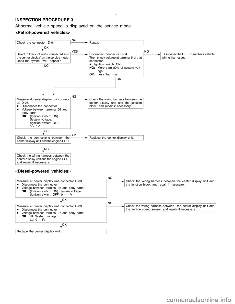
INSPECTION PROCEDURE 3
Abnormal vehicle speed is displayed on the service mode.
OK
NGRepair.
Measure at center display unit connec-
tor D-03.
DDisconnect the connector.
DVoltage between terminal 36 and
body earth.
OK:(Ignition switch: ON)
System voltage.
(Ignition switch: OFF)
0-1VNGCheck the wiring harness between the
center display unit and the junction
block, and repair if necessary.
NG
Check the wiring harness between the
center display unit and the engine-ECU,
and repair if necessary.
Select “Check of units connected into
the center display” on the service mode.
Does the symbol “MU” appear?YES NGDisconnect MUT-
II. Then check vehicle
wiring harnesses.Disconnect connector D-04.
Then check voltage at terminal 5 of that
connector.
DIgnition switch: ON
NG:More than 80% of system volt-
age
OK:Less than that
OK NO
OK
Check the connections between the
center display unit and the engine-ECU.OKReplace the center display unit.
Check the connector: D-04
Measure at center display unit connector D-03.
DDisconnect the connector.
DVoltage between terminal 36 and body earth.
OK:(Ignition switch: ON) System voltage.
(Ignition switch: OFF) 0 - 1 VNGCheck the wiring harness between the center display unit and
the junction block, and repair if necessary.
OK
Measure at center display unit connector D-03 .
DDisconnect the connector.
DVoltage between terminal 27 and body earth.
OK:HI: System voltage.
Lo: 0 - 1VNGCheck the wiring harness between the center display unit and
the vehicle speed sensor, and repair if necessary.
OK
Replace the center display unit.
www.WorkshopManuals.co.uk
Purchased from www.WorkshopManuals.co.uk
Page 1634 of 1839
CHASSIS ELECTRICAL -Clock or Center Display54A-64
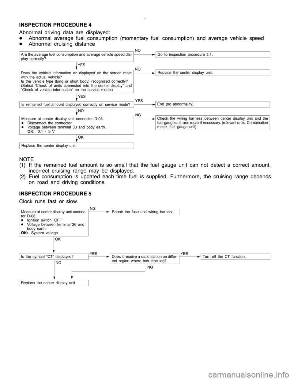
INSPECTION PROCEDURE 4
Abnormal driving data are displayed:
DAbnormal average fuel consumption (momentary fuel consumption) and average vehicle speed
DAbnormal cruising distance
Are the average fuel consumption and average vehicle speed dis-
play correctly?NOGo to inspection procedure 3.1.
YES
Does the vehicle information on displayed on the screen meet
with the actual vehicle?
Is the vehicle type (long or short body) recognized correctly?
(Select “Check of units connected into the center display” and
“Check of vehicle information” on the service mode.)NOReplace the center display unit.
YES
Is remained fuel amount displayed correctly on servicemode?YESEnd (no abnormality).
NO
Measure at center display unit connector D-03.
DDisconnect the connector.
DVoltage between terminal 33 and body earth.
OK:0.1 - 3 VNGCheck the wiring harness between center display unit and the
fuel gauge unit, and repair ifnecessary. (relevant units: Combination
meter, fuel gauge unit)
OK
Replace the center display unit.
NOTE
(1) If the remained fuel amount is so small that the fuel gauge unit can not detect a correct amount,
incorrect cruising range may be displayed.
(2) Fuel consumption is updated each time fuel is supplied. Furthermore, the cruising range depends
on road and driving conditions.
INSPECTION PROCEDURE 5
Clock runs fast or slow.
NGRepair the fuse and wiring harness.
OK
YES
Does it receive a radio station on differ-
ent region where has timelag?YESTurn off the CT function.
NO
Replace the center display unit.
Measure at center display unit connec-
tor D-03.
DIgnition switch: OFF
DVoltage between terminal 26 and
body earth.
OK:System voltage
Is the symbol “CT” displayed?
NO
www.WorkshopManuals.co.uk
Purchased from www.WorkshopManuals.co.uk
Page 1635 of 1839
CHASSIS ELECTRICAL -Clock or Center Display54A-65
INSPECTION PROCEDURE 6
The display screen is dim.
NOMeasure at center display unit connec-
tor D-03.
DDisconnect the connector.
DVoltage between terminal 24 and
body earth.
OK:0 V (Lighting switch: off)
System voltage (Lighting
switch: ON)NGRepair the fuse and wiring harness.
Is the brightness of the center display
set correctly?NOAdjust the brightness of display on set-
ting mode.
OK
Replace the center display unit.
OK
Replace the center display unit.
YES
Measure at center display unit connec-
tor D-03.
DDisconnect the connector.
DRheostat: max
DVoltage between terminal 32 and
body earth.
OK:Low voltage (0 - 3 V)NGRepair the wiring harness.
Does the brightness of display change
when the lighting switch is on or off?
YES
www.WorkshopManuals.co.uk
Purchased from www.WorkshopManuals.co.uk
Page 1636 of 1839
CHASSIS ELECTRICAL -Clock or Center Display54A-66
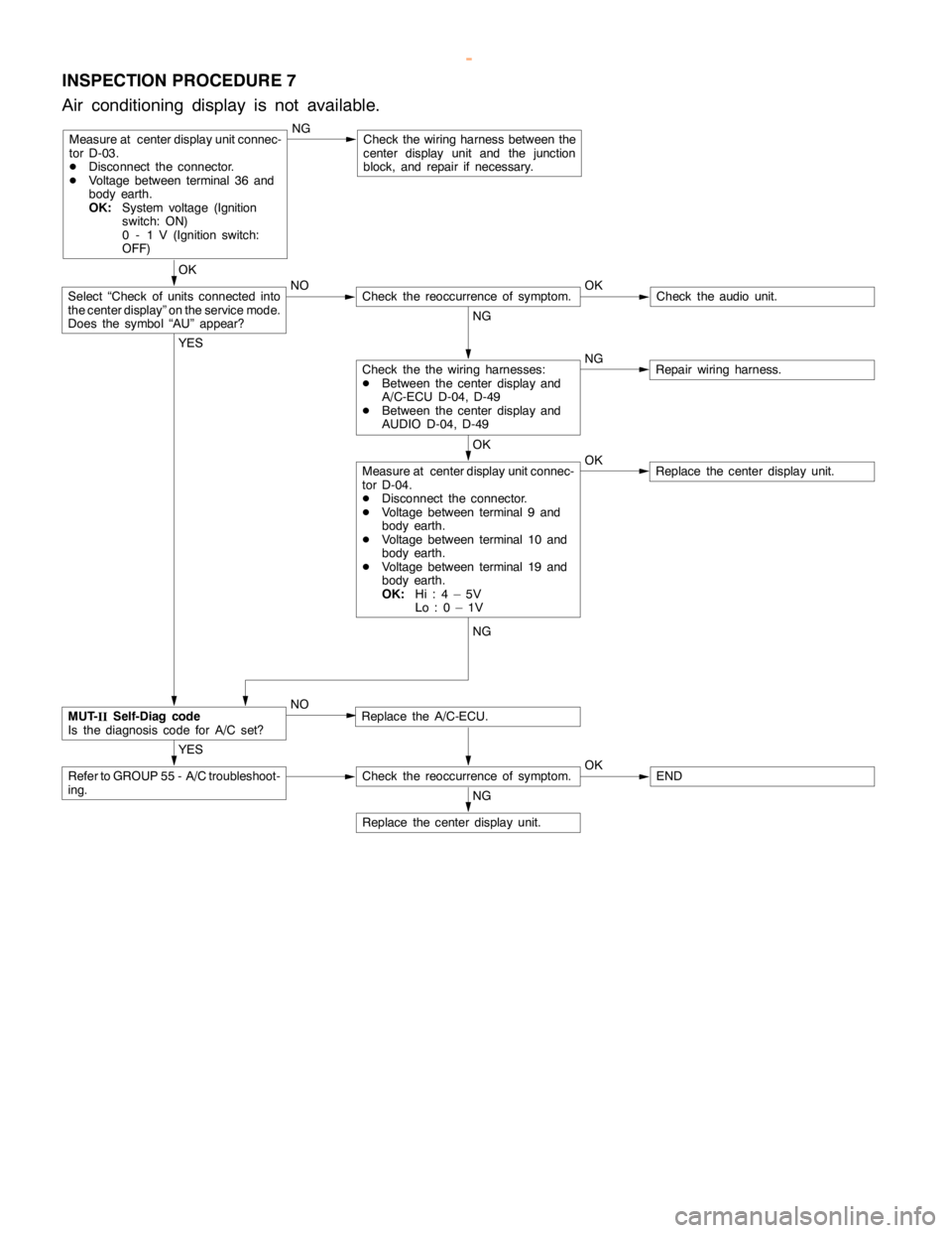
INSPECTION PROCEDURE 7
Air conditioning display is not available.
Measure at center display unit connec-
tor D-03.
DDisconnect the connector.
DVoltage between terminal 36 and
body earth.
OK:System voltage (Ignition
switch: ON)
0 - 1 V (Ignition switch:
OFF)NGCheck the wiring harness between the
center display unit and the junction
block, and repair if necessary.
OK
NO OK
Check theaudio unit.
NG
NG
Repair wiring harness.
OK
OK
Replace the center display unit.
YES
Replace the A/C-ECU.
YES
Refer to GROUP 55 - A/C troubleshoot-
ing.Check the reoccurrence of symptom.OKEND
NG
Replace the center display unit.
Measure at center display unit connec-
tor D-04.
DDisconnect the connector.
DVoltage between terminal 9 and
body earth.
DVoltage between terminal 10 and
body earth.
DVoltage between terminal 19 and
body earth.
OK:Hi:4–5V
Lo:0–1V
Check the the wiring harnesses:
DBetween the center display and
A/C-ECU D-04, D-49
DBetween the center display and
AUDIO D-04, D-49
Check the reoccurrence of symptom.Select “Check of units connected into
the center display” on the service mode.
Does the symbol “AU” appear?
MUT-
IISelf-Diag code
Is the diagnosis code for A/C set?NG
NO
www.WorkshopManuals.co.uk
Purchased from www.WorkshopManuals.co.uk
Page 1663 of 1839
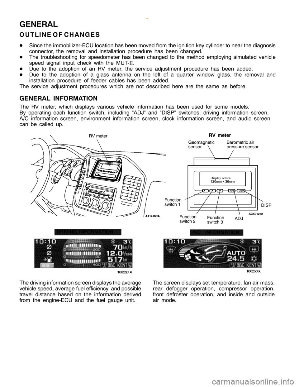
G
EN ER AL
O UTLIN E OF CHANG ES
D Sin ce th e im mobiliz e r-E C U lo ca tio n has been m ove d fr o m th e ig nit io n ke y cylin der to near th e dia gnosis
c o nnecto r, th e re m ova l and in sta lla tio n pro ce dure has been ch anged.
D The tr o uble sh ootin g fo r sp eedom ete r has been ch anged to th e meth od em plo yin g sim ula te d ve hic le
s p eed sig nal in put ch eck wit h th e MUT-II .
D Due to th e adoptio n of an RV mete r, th e se rv ic e adju stm ent pro ce dure has been added.
D Due to th e adoptio n of a gla ss ante nna on th e le ft of a quarte r win dow gla ss, th e re m ova l and
i n sta lla tio n pro ce dure of fe eder ca ble s has been added.
T he se rv ic e adju stm ent pro ce dure s whic h are not describ ed here are th e sa m e as befo re .
G EN ER AL IN FO RM ATIO N
T he RV mete r, whic h dis p la ys va rio us ve hic le in fo rm atio n has been use d fo r so m e models .
B y opera tin g each fu nctio n sw it c h , in clu din g ”A D J” and ”D IS P” sw it c h es, driv in g in fo rm atio n scre en,
A /C in fo rm atio n scre en, envir o nm ent in fo rm atio n scre en, clo ck in fo rm atio n scre en, and audio scre en
c a n be ca lle d up. F
unctio n
s w it c h 1 A
D J F
unctio n
s w it c h 3 F
unctio n
s w it c h 2 D
IS P G
eom agnetic
s e nso r B
aro m etr ic air
p re ssu re se nso r A
/C IN FO RM ATIO N
T he driv in g in fo rm atio n scre en dis p la ys th e ave ra ge
v e hic le sp eed,a ve ra ge fu ele ff ic ie ncy, a nd possib le
t r a ve l dis ta nce base d on th e in fo rm atio n deriv e d
f r o m th e engin e-E C U and th e fu el gauge unit . T
he scre en dis p la ys se t te m pera tu re , fa n air m ass,
r e ar defo gger opera tio n, co m pre sso r opera tio n,
f r o nt defr o ste r opera tio n, and in sid e and outs id e
a ir m ode.
w
ww.W ork sh opM an uals .c o .u k
P urc h ased f r o m w ww.W ork sh opM an uals .c o .u k
Page 1667 of 1839
D
IS P A
D J F
unctio n sw it c h 3 F
unctio n
s w it c h 2 C
onte nts R
efe re nce
P age A
uto m atic mode dia gnosis c
h ecks ve hic le sig nalin fo rm atio n co m munic a tio n, audio ,A /C ,
f u el in fo rm atio n, monit o r auto m atic a lly wheneve r fu nctio n
s w it c h 1(N EXT) is pre sse d. 5
4A -7 D
ia gnosis mode c
h ecks ve rs io n, ve hic le sig nal, co m munic a tio n in fo rm atio n (a udio ,
A /C ,and fu el) . 5
4A -9 H
is to ry m ode d
is p la ys his to ry ofco m munic a tio n erro r. 5
4A -1 1 M
onit o r h
k D
is p la y ch eck m ode c
h ecks th e dis p la y. c
h eck m ode G
eom agnetic ch eck
m ode c
h ecks th e geom agnetic se nso r. A
lt im ete r adju st m ode a
dju sts th e alt im ete r.