Page 58 of 280
SEATS AND SEATBELTS
3–30
G28L088d
The front air bags MAY DEPLOY when...
The front air bags may deploy if the bottom
of the vehicle suffers a moderate to severe
impact (undercarriage damage).
Examples of some typical conditions are
shown in the illustration:1-Collision with an elevated median/is-
land or curb
2-Vehicle travels over a deep hole/po-
thole
3-Vehicle drives down a steep slope and
hits the groundBecause the front air bags may deploy in
certain types of unexpected impacts as
shown in the illustration that can easily move
you out of position, it is important to always
properly wear your seat belts. Your seat belts
will help you to keep a safe distance from the
steering wheel and instrument panel during
the initial stages of air bag deployment. The
initial stage of air bag inflation is the most
forceful and can possibly cause serious or
fatal injuries if you contact it at this stage.
Page 59 of 280

SEATS AND SEATBELTS
3–31
G28G326a
WARNING
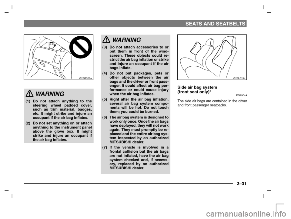
(1) Do not attach anything to the
steering wheel padded cover,
such as trim material, badges,
etc. It might strike and injure an
occupant if the air bag inflates.
(2) Do not set anything on or attach
anything to the instrument panel
above the glove box. It might
strike and injure an occupant if
the air bag inflates.
WARNING
(3) Do not attach accessories to or
put them in front of the wind-
screen. These objects could re-
strict the air bag inflation or strike
and injure an occupant if the air
bags inflate.
(4) Do not put packages, pets or
other objects between the air
bags and the driver or front pass-
enger. It could affect air bag per-
formance or could cause injury
when the air bag inflates.
(5) Right after the air bag inflation,
several air bag system compo-
nents will be hot. Do not touch
them; you could be burned.
(6) The air bag system is designed to
work only once. Once the air bags
have deployed, they will not work
again. They must promptly be re-
placed and the entire air bag sys-
tem inspected by an authorized
MITSUBISHI dealer.
(7) If the vehicle is involved in a
frontal collision but the air bags
are not inflated, have the air bag
system checked and, if necess-
ary, replaced by an authorized
MITSUBISHI dealer.
G28L015a
Side air bag system
(front seat only)*
EG29D-A
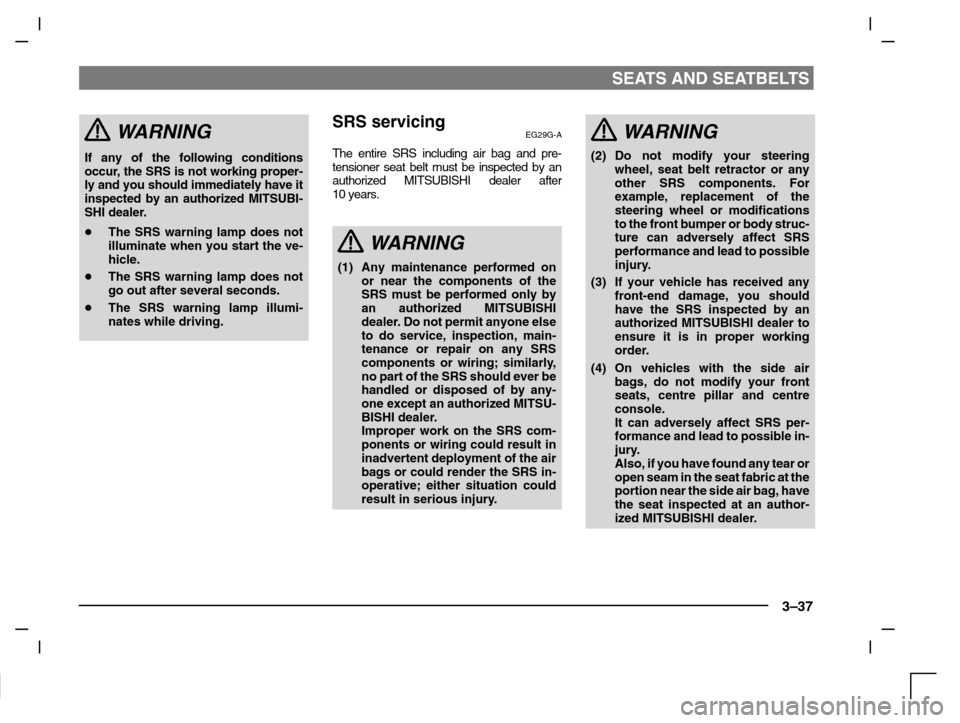
The side air bags are contained in the driver
and front passenger seatbacks.
Page 65 of 280

SEATS AND SEATBELTS
3–37
WARNING
If any of the following conditions
occur, the SRS is not working proper-
ly and you should immediately have it
inspected by an authorized MITSUBI-
SHI dealer.
�The SRS warning lamp does not
illuminate when you start the ve-
hicle.
�The SRS warning lamp does not
go out after several seconds.
�The SRS warning lamp illumi-
nates while driving.
SRS servicingEG29G-A
The entire SRS including air bag and pre-
tensioner seat belt must be inspected by an
authorized MITSUBISHI dealer after
10 years.
WARNING
(1) Any maintenance performed on
or near the components of the
SRS must be performed only by
an authorized MITSUBISHI
dealer. Do not permit anyone else
to do service, inspection, main-
tenance or repair on any SRS
components or wiring; similarly,
no part of the SRS should ever be
handled or disposed of by any-
one except an authorized MITSU-
BISHI dealer.
Improper work on the SRS com-
ponents or wiring could result in
inadvertent deployment of the air
bags or could render the SRS in-
operative; either situation could
result in serious injury.
WARNING
(2) Do not modify your steering
wheel, seat belt retractor or any
other SRS components. For
example, replacement of the
steering wheel or modifications
to the front bumper or body struc-
ture can adversely affect SRS
performance and lead to possible
injury.
(3) If your vehicle has received any
front-end damage, you should
have the SRS inspected by an
authorized MITSUBISHI dealer to
ensure it is in proper working
order.
(4) On vehicles with the side air
bags, do not modify your front
seats, centre pillar and centre
console.
It can adversely affect SRS per-
formance and lead to possible in-
jury.
Also, if you have found any tear or
open seam in the seat fabric at the
portion near the side air bag, have
the seat inspected at an author-
ized MITSUBISHI dealer.
Page 79 of 280

INSTRUMENTS AND CONTROLS
4–13
E11D026a
Turn/lane-change signalsEE11D-N
The turn-signal lamps flash when the switch
is operated (with the ignition switch “ON”). At
the same time, the turn signal indicator
flashes.
1-Turn-signals
When making a normal turn, use posi-
tion (1). The lever will return automati-
cally when cornering is completed.
There are times when the lever will not
return after cornering. This occurs
when the steering wheel is turned only
slightly.
In such cases, return the lever by
hand.
2-Lane-change signals
When changing lanes, use position
(2). It will return to the neutral position
when released.NOTE
If the lamp flashes unusually quickly, the bulb
in a turn–signal lamp may have burned out.
Have the vehicle inspected by an authorized
MITSUBISHI dealer.
E01G011a
Headlamp levelling switchEE01GMF
The angle of the headlamp beam varies
depending upon the load carried by the ve-
hicle.
The headlamp levelling switch can be
used to adjust the headlamp illumination
distance (when the lower beam is illumi-
nated) so that the headlamps’ glare does
not distract the drivers of approaching ve-
hicles. Set the switch (referring to the fol-
lowing table) to the appropriate position
according to the number of people and the
load in the vehicle.
Page 88 of 280
INSTRUMENTS AND CONTROLS
4–22
E23A001a
Horn switchEE23A-Ac
When the ignition switch is in the “ON” or
“ACC” position, pressing the “” mark on
the steering wheel, causes the horn to
sound.
E19A134a
Room lampsEE19AAZ
Vehicles without sunroof
Room lamp1(OFF)
-The lamp goes out.
2(�)
-The lamp illuminates when a
door or the tailgate is opened
and goes out when it is closed.
3(ON)
-The lamp illuminates.
F19A037a
Spot lamps*4 - The lamp goes out.
5 - The lamp illuminates.
Page 101 of 280

Starting and driving
Running-in recommendations 5–2. . . . . . . . . . . . . .
Fuel selection 5–3. . . . . . . . . . . . . . . . . . . . . . . . . . . . .
Filling the fuel tank 5–3. . . . . . . . . . . . . . . . . . . . . . . .
Catalytic converter 5–5. . . . . . . . . . . . . . . . . . . . . . . .
Economical driving 5–6. . . . . . . . . . . . . . . . . . . . . . . .
Tr ailer towing 5–7. . . . . . . . . . . . . . . . . . . . . . . . . . . . .
Ignition switch 5–9. . . . . . . . . . . . . . . . . . . . . . . . . . . .
Starting 5–12. . . . . . . . . . . . . . . . . . . . . . . . . . . . . . . . .
Manual transmission 5–14. . . . . . . . . . . . . . . . . . . . .
Automatic transmission INVECS–II 4A/T,
Sports Mode 4A/T
(Intelligent & Innovative Vehicle Electronic
Control System II) 5–16. . . . . . . . . . . . . . . . . . . . . . . .
Operation of the automatic transmission
INVECS-II 5–23. . . . . . . . . . . . . . . . . . . . . . . . . . . . . . .
Parking brake 5–25. . . . . . . . . . . . . . . . . . . . . . . . . . . .
Parking 5–26. . . . . . . . . . . . . . . . . . . . . . . . . . . . . . . . .
Braking 5–27. . . . . . . . . . . . . . . . . . . . . . . . . . . . . . . . .
Anti–lock brake system (ABS)* 5–28. . . . . . . . . . . .
Steering wheel height adjustment 5–30. . . . . . . . . .
Power steering system 5–31. . . . . . . . . . . . . . . . . . .
Inside rear-view mirror 5–31. . . . . . . . . . . . . . . . . . . .
Outside rear-view mirror 5–31. . . . . . . . . . . . . . . . . .
Manual remote-controlled outside rear-view
mirrors* 5–32. . . . . . . . . . . . . . . . . . . . . . . . . . . . . . . . .
Electric remote–controlled outside
rear–view mirrors* 5–32. . . . . . . . . . . . . . . . . . . . . . . .
Traction control (TCL)* 5–34. . . . . . . . . . . . . . . . . . . .
Auto–speed (cruise) control* 5–36. . . . . . . . . . . . . .
Page 109 of 280

STARTING AND DRIVING
5–9
(6) The heavier weight and higher rolling
and air resistance will increase fuel con-
sumption.
Additional precautions for vehicles
equipped with an automatic
transmission
The “2” position (INVECS–II 4A/T) or 2nd
gear (INVECS–II Sport Mode 4A/T) is re-
commended on slopes or at low speed. Use
the “L” position (INVECS–II 4A/T) or 1st gear
(INVECS–II Sport Mode 4A/T) in mountain-
ous areas in order to make better use of en-
gine braking and to assist the brake system.
However, be sure that the speed does not
exceed the maximum speed limit for the se-
lected gear.
For maximum speed of the vehicles
equipped with INVECS–II 4A/T, refer to the
description of the “Possible driving speed”
on page 5–24.Vehicles with automatic transmission
I21A070a
Ignition switchEI21AAGe
1-The engine is stopped, and the steer-
ing wheel is locked. The key can only
be inserted and removed only when
the switch is in this position.
2-The engine is stopped, but the radio,
cigarette lighter and other electrical
devices can be operated.
3-The engine is running and all the ve-
hicle’s electrical devices can be oper-
ated.
4-The starter motor operates. After the
engine has started, release the key
and it will automatically return to the
“ON” position.
Vehicles with manual transmission
I21A031a
Page 111 of 280

STARTING AND DRIVING
5–11
CAUTION
(1) Do not remove the ignition key
from the ignition switch while
driving. The steering wheel will
lock, causing loss of control.
(2) If the engine is stopped while
driving, the brake servomechan-
ism will cease to function and
braking efficiency will deterio-
rate. Also, the power steering
system will not function and it will
require greater manual effort to
operate the steering.
(3) Do not leave the key in the “ON”
position for a long time when the
engine is not running, doing so
will cause the battery to be dis-
charged.
(4) Do not turn the key to the
“START” position when the en-
gine is running, doing so could
damage the starter motor.
I01B015a
How to lock and unlock the steer-
ing wheel
EI01B-Kb
To lockRemove the key at the “LOCK” position.
Turn the steering wheel until it is locked.
To unlockTurn the key to the “ACC” position while
moving the steering wheel slightly.
CAUTION
Remove the key when leaving the ve-
hicle.
NOTEIf the front wheels are turned, the anti-theft
lock may sometimes make it difficult to turn
the key from “LOCK” to “ACC”. Firmly turn
the steering wheel to the left or to the right as
you turn the key.