Page 514 of 1111

EM±2
± ENGINE MECHANICAL (2JZ±GE)CO/HC
1356 Author�: Date�:
2000 LEXUS GS300/GS400 (RM718U)
If the CO/HC concentration does not comply with regulations,
troubleshoot in the order given below.
(a) Check heated oxygen sensors operation.
(See page DI±44)
(b) See the table below for possible causes, and then inspect
and correct the applicable causes if necessary.
HCCOPhenomenonCauses
HighNormalRough idle1. Faulty ignitions:
�Incorrect timing
�Fouled, shorted or improperly gapped plugs
�Open or crossed high±tension cords
2. Incorrect valve clearance
3. Leaky intake and exhaust valves
4. Leaky cylinder
HighLowRough idle
(Fluctuating HC reading)1. Vacuum leaks:
�PCV hose
�Intake manifold
�Throttle body
�Cylinder head gasket
2. Lean mixture causing misfire
HighHighRough idle
(Black smoke from exhaust)1. Restricted air filter
2. Plugged PCV valve
3. Faulty SFI systems:
�Faulty pressure regulator
�Faulty ECM
�Faulty injector
�Faulty throttle position sensor
�Faulty mass air flow meter
Page 516 of 1111
EM0D4±01
± ENGINE MECHANICAL (2JZ±GE)IDLE SPEED
EM±13
1367 Author�: Date�:
2000 LEXUS GS300/GS400 (RM718U)
IDLE SPEED
INSPECTION
1. INITIAL CONDITIONS
(a) Engine at normal operating temperature
(b) Air cleaner installed
(c) All pipes and hoses of air induction system connected
(d) All accessories switched OFF
(e) All vacuum lines properly connected
(f) SFI system wiring connectors fully plugged
(g) Ignition timing checked correctly
(h) Transmission in neutral position
2. CONNECT LEXUS HAND±HELD TESTER OR OBDII SCAN TOOL (See page EM±12)
3. INSPECT IDLE SPEED
(a) Race the engine speed at 2,500 rpm for approx. 90 seconds.
(b) Check the idle speed.
Idle speed: 700 ± 50 rpm
If the idle speed is not as specified, check the throttle body.
4. DISCONNECT LEXUS HAND±HELD TESTER OR OBDII SCAN TOOL
Page 518 of 1111

A11128
Accelerator Pedal Position Sensor Connector
Throttle Control Motor Connector
Throttle Body and Intake Air Connector Assembly
Water Bypass HoseVSV Connector
for EVAP
EVAP Hose
� Gasket Air Assist Hose Engine Wire
Oil Filler Cap
No.3 Timing Belt Cover
Gasket
No.2 Timing Belt Cover
GasketThrottle
Position
Sensor
Connector
Vacuum Hose
(from Actuator for ACIS)
Water Bypass Hose
Engine Wire Protector
High±Tension
Cord w/ Clamp
No.1 Cylinder
Head Cover
Gasket
Timing Belt
x 6
Timing Belt Guide
Gasket
x 5 No.1 Timing Belt Cover
Crankshaft
Pulley
21 (210, 15)
Drive Belt Tensioner
330 (3,300, 243)
Camshaft
Timing Pulley
(VVT±i Pulley)81 (810, 60)
Straight
Screw Plug
15 (150, 11)Seal Washer
Camshaft
Timing Oil
Control Valve
Camshaft Timing
Oil Control
Valve Connector� Gasket
Oil Control Valve Filter
� O±Ring
No.1 Oil PipeUnion Bolt
55 (550, 41)
Idler Pulley
Crankshaft Timing Pulley
Timing Belt Plate
Timing Belt Tensioner
N´m (kgf´cm, ft´lbf) : Specified torque
35 (350, 26)�
8.0 (80, 71 in.´lbf)
27 (270, 20)
� Non±reusable part
� Precoated part
Dust Boot
Engine Wire ClampPCV Hose
Vacuum Hose
(from No.2
Vacuum Pipe)
± ENGINE MECHANICAL (2JZ±GE)TIMING BELT
EM±15
1369 Author�: Date�:
2000 LEXUS GS300/GS400 (RM718U)
Page 521 of 1111

P11002
A11127
SST
A11126
5 mm
Hexagon
Wrench
A02662
Gasket
Union Bolt
Oil Control
Valve Filter
EM±18
± ENGINE MECHANICAL (2JZ±GE)TIMING BELT
1372 Author�: Date�:
2000 LEXUS GS300/GS400 (RM718U)
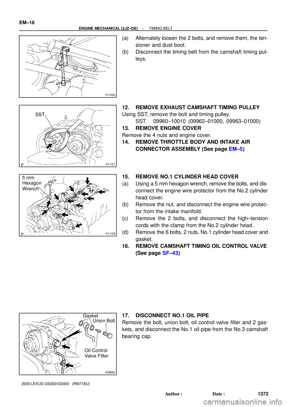
(a) Alternately loosen the 2 bolts, and remove them, the ten-
sioner and dust boot.
(b) Disconnect the timing belt from the camshaft timing pul-
leys.
12. REMOVE EXHAUST CAMSHAFT TIMING PULLEY
Using SST, remove the bolt and timing pulley.
SST 09960±10010 (09962±01000, 09963±01000)
13. REMOVE ENGINE COVER
Remove the 4 nuts and engine cover.
14. REMOVE THROTTLE BODY AND INTAKE AIR
CONNECTOR ASSEMBLY (See page EM±5)
15. REMOVE NO.1 CYLINDER HEAD COVER
(a) Using a 5 mm hexagon wrench, remove the bolts, and dis-
connect the engine wire protector from the No.2 cylinder
head cover.
(b) Remove the nut, and disconnect the engine wire protec-
tor from the intake manifold.
(c) Remove the 2 bolts, and disconnect the high±tension
cords with the clamp from the No.2 cylinder head.
(d) Remove the 6 bolts, 2 nuts, No.1 cylinder head cover and
gasket.
16. REMOVE CAMSHAFT TIMING OIL CONTROL VALVE
(See page SF±43)
17. DISCONNECT NO.1 OIL PIPE
Remove the bolt, union bolt, oil control valve filter and 2 gas-
kets, and disconnect the No.1 oil pipe from the No.3 camshaft
bearing cap.
Page 528 of 1111

A02726
Seal WasherSet BoltHold
Straight
Screw
Plug
A02722
Mesh Part
Frame Part
A11126
5 mm
Hexagon
Wrench
A02661
Front MarkSST
± ENGINE MECHANICAL (2JZ±GE)TIMING BELT
EM±25
1379 Author�: Date�:
2000 LEXUS GS300/GS400 (RM718U)
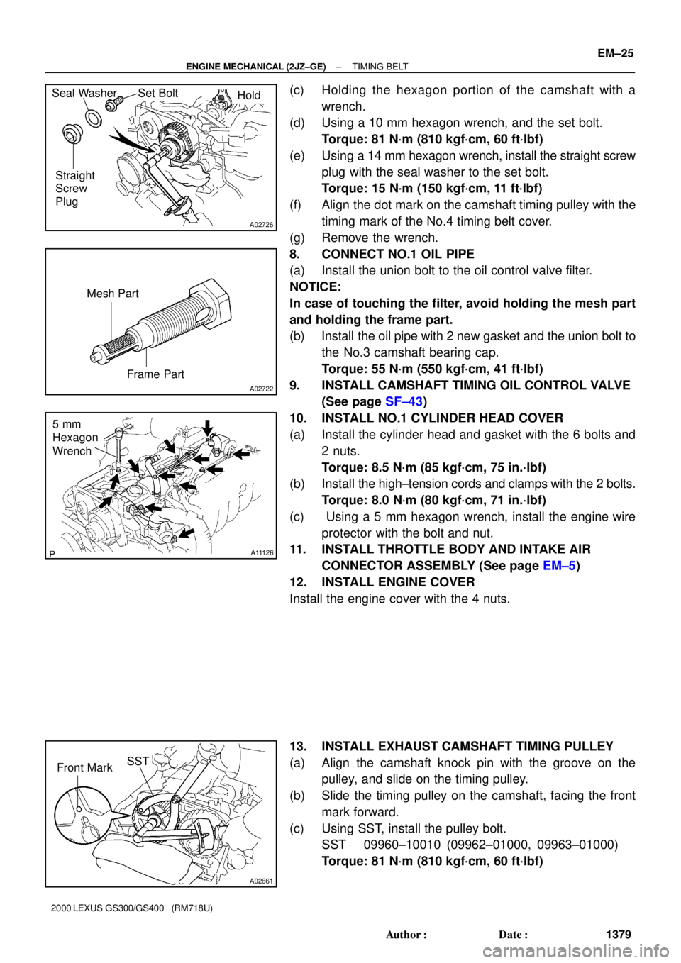
(c) Holding the hexagon portion of the camshaft with a
wrench.
(d) Using a 10 mm hexagon wrench, and the set bolt.
Torque: 81 N´m (810 kgf´cm, 60 ft´lbf)
(e) Using a 14 mm hexagon wrench, install the straight screw
plug with the seal washer to the set bolt.
Torque: 15 N´m (150 kgf´cm, 11 ft´lbf)
(f) Align the dot mark on the camshaft timing pulley with the
timing mark of the No.4 timing belt cover.
(g) Remove the wrench.
8. CONNECT NO.1 OIL PIPE
(a) Install the union bolt to the oil control valve filter.
NOTICE:
In case of touching the filter, avoid holding the mesh part
and holding the frame part.
(b) Install the oil pipe with 2 new gasket and the union bolt to
the No.3 camshaft bearing cap.
Torque: 55 N´m (550 kgf´cm, 41 ft´lbf)
9. INSTALL CAMSHAFT TIMING OIL CONTROL VALVE
(See page SF±43)
10. INSTALL NO.1 CYLINDER HEAD COVER
(a) Install the cylinder head and gasket with the 6 bolts and
2 nuts.
Torque: 8.5 N´m (85 kgf´cm, 75 in.´lbf)
(b) Install the high±tension cords and clamps with the 2 bolts.
Torque: 8.0 N´m (80 kgf´cm, 71 in.´lbf)
(c) Using a 5 mm hexagon wrench, install the engine wire
protector with the bolt and nut.
11. INSTALL THROTTLE BODY AND INTAKE AIR
CONNECTOR ASSEMBLY (See page EM±5)
12. INSTALL ENGINE COVER
Install the engine cover with the 4 nuts.
13. INSTALL EXHAUST CAMSHAFT TIMING PULLEY
(a) Align the camshaft knock pin with the groove on the
pulley, and slide on the timing pulley.
(b) Slide the timing pulley on the camshaft, facing the front
mark forward.
(c) Using SST, install the pulley bolt.
SST 09960±10010 (09962±01000, 09963±01000)
Torque: 81 N´m (810 kgf´cm, 60 ft´lbf)
Page 533 of 1111
A11125
Throttle Body and Intake Air Connector AssemblyWater Bypass Hose
PCV Hose
EVAP Hose
� Gasket
Air Assist Hose
Vacuum
Hose
PS Air Hose
Air Intake Chamber
Engine Wire
Clamp
Drive Belt
TensionerClamp Bracket
Ground StrapFuel Pressure
Pulsation Damper Clamp Bracket
Water Bypass
Outlet
No.1 Water Bypass Pipe
No.3 Timing Belt Cover� O±Ring
Oil Filler CapFuel Inlet Pipe
PS Air Hose
Hose
Clamp
Timing Belt
Tensioner
PS Pump Stay
Oil Dipstick
and Guide
for A/T
PS Vane Pump Water Bypass Hose
28 (280, 21)
Engine Wire
� O±Ring
No.2 Timing Belt Cover
GasketGasket
21 (210, 15)
32.5 (325, 24)
� Gasket
� Gasket
Engine Wire
Clamp
� O±Ring � O±RingOil Dipstick and
Guide for Engine
27 (270, 20)
58 (590, 43)39.2 (400, 29)N´m (kgf´cm, ft´lbf) : Specified torque
� Non±reusable Part
Dust BootEngine Wire
Clamp
No.2 Vacuum Pipe
Hose Clamp
Vacuum Control
Valve Set
EM±30
± ENGINE MECHANICAL (2JZ±GE)CYLINDER HEAD
1384 Author�: Date�:
2000 LEXUS GS300/GS400 (RM718U)
Page 539 of 1111

A02819
A09752
A02735
EM±34
± ENGINE MECHANICAL (2JZ±GE)CYLINDER HEAD
1388 Author�: Date�:
2000 LEXUS GS300/GS400 (RM718U)
(b) Remove the 3 bolts and nuts holding the front exhaust
pipe to the exhaust manifold.
(c) Remove the 2 bolts and pipe support bracket.
(d) Disconnect the front exhaust pipe from the exhaust man-
ifold, and remove the 2 gaskets.
10. REMOVE EXHAUST MANIFOLD
(a) Disconnect the 3 heated oxygen sensor connectors and
clamp.
(b) Remove the clamp and case clamp.
(c) Using a 14 mm deep socket wrench, remove the 8 nuts,
exhaust manifold and 2 gaskets.
11. REMOVE WATER BYPASS OUTLET AND NO.1
WATER BYPASS PIPE (See page CO±11)
12. REMOVE THROTTLE BODY AND INTAKE AIR
CONNECTOR ASSEMBLY (See page EM±5)
13. REMOVE OIL DIPSTICK AND GUIDE FOR ENGINE
(See page LU±6)
14. REMOVE OIL DIPSTICK AND GUIDE FOR A/T
(See page EM±62)
15. REMOVE AIR INTAKE CHAMBER (See page SF±46)
16. REMOVE VACUUM CONTROL VALVE SET AND NO.2
VACUUM PIPE
(a) Disconnect the VSV connector for the ACIS.
(b) Remove the 3 nuts, vacuum control valve set and No.2
vacuum pipe.
(c) Disconnect the engine wire clamp from the clamp bracket
of the No.2 vacuum pipe.
17. REMOVE NO.3 TIMING BELT COVER
18. REMOVE IGNITION COILS AND HIGH±TENSION
CORD SET ASSEMBLY (See page IG±7)
19. REMOVE SPARK PLUGS
Page 555 of 1111

EM0D2±04
A11131
(d) (g)
(f)
(e) (b)
(c)
A11130
(h)(i)
(j)
(k)
A11129
(o)
(n)
(o)
± ENGINE MECHANICAL (2JZ±GE)VALVE CLEARANCE
EM±5
1359 Author�: Date�:
2000 LEXUS GS300/GS400 (RM718U)
VALVE CLEARANCE
ADJUSTMENT
HINT:
Inspect and adjust the valve clearance when the engine is cold.
1. REMOVE ENGINE COVER
Remove the 4 nuts and engine cover.
2. DRAIN ENGINE COOLANT
3. REMOVE INTAKE AIR RESONATOR
4. REMOVE THROTTLE BODY AND INTAKE AIR
CONNECTOR ASSEMBLY
(a) Disconnect the accelerator cable from the throttle body.
(b) Disconnect the engine wire clamp from the clamp bracket
of the throttle body.
(c) Disconnect the engine wire from the clamp on the throttle
body bracket.
(d) Disconnect the accelerator pedal position sensor con-
nector.
(e) Disconnect the throttle control motor connector.
(f) Disconnect the throttle position sensor connector.
(g) Disconnect the air assist hose from the intake air connec-
tor.
(h) Disconnect the PCV hose from the intake air connector.
(i) Disconnect the VSV connector for EVAP.
(j) Disconnect the EVAP hose (from charcoal canister) from
the VSV for EVAP.
(k) Disconnect the vacuum hose (from No.2 vacuum pipe)
from the No.1 vacuum pipe.
(l) Remove the 2 nuts holding the throttle body bracket to the
cylinder head.
(m) Remove the 4 bolts and 2 nuts holding the intake air con-
nector to the air intake chamber.
(n) Disconnect the vacuum hose (from actuator for ACIS)
from the No.1 vacuum pipe.
(o) Disconnect the 2 water bypass hoses from the throttle
body, and remove the throttle body together with the in-
take air connector and gasket.