Page 920 of 1111
 or less
Engine Idling Engine Stopped SR±4
± STEERINGPOWER STEERING FLUID
2174 Author�: Date�:
2000 LEXUS GS300/GS400 (RM718U)
INSPECTI")
SR0DH±01
F03835
R07281
Normal Abnormal
R11361
5 mm (0.2 in.) or less
Engine Idling Engine Stopped SR±4
± STEERINGPOWER STEERING FLUID
2174 Author�: Date�:
2000 LEXUS GS300/GS400 (RM718U)
INSPECTION
1. CHECK FLUID LEVEL
(a) Keep the vehicle level.
(b) With the engine stopped, check the fluid level in the oil
reservoir.
If necessary, add fluid.
Fluid: ATF DEXRON® II or III
HINT:
Check that the fluid level is within the HOT LEVEL range on the
reservoir cap dipstick.
If the fluid is cold, check that it is within the COLD LEVEL range.
(c) Start the engine and run it at idle.
(d) Turn the steering wheel from lock to lock several times to
boost fluid temperature.
Fluid temperature: 80°C (176°F)
(e) Check for foaming or emulsification.
If there is foaming or emulsification, bleed power steering sys-
tem. (See page SR±3)
(f) With the engine idling, measure the fluid level in the oil
reservoir.
(g) Stop the engine.
(h) Wait a few minutes and remeasure the fluid level in the oil
reservoir.
Maximum fluid level rise: 5 mm (0.20 in.)
If a problem is found, bleed power steering system.
(See page SR±3)
(i) Check the fluid level.
Page 921 of 1111
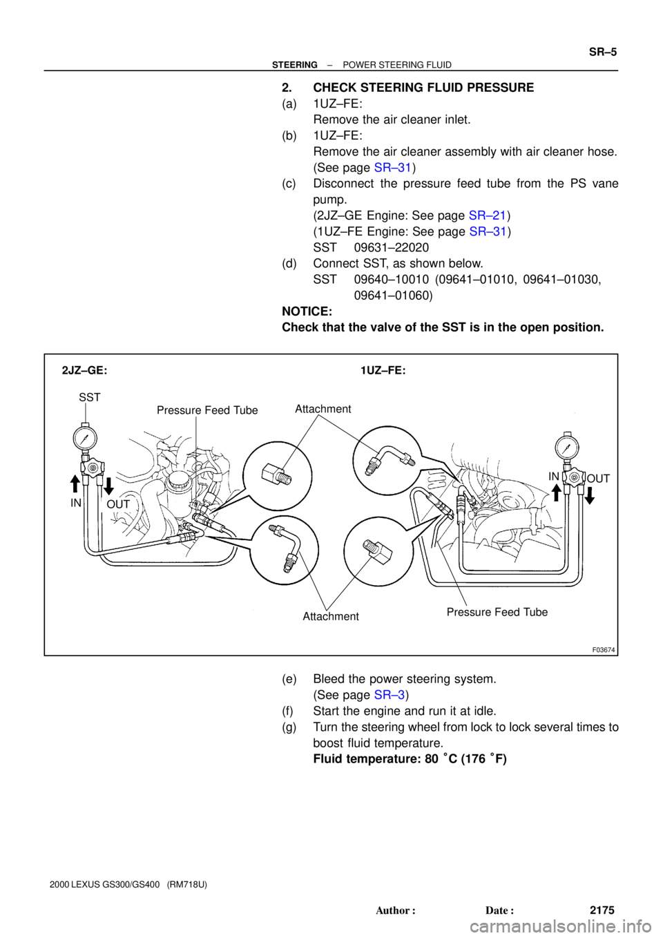
F03674
SST
IN
OUT
Pressure Feed Tube Attachment 2JZ±GE: 1UZ±FE:
Attachment
OUT IN Pressure Feed Tube
± STEERINGPOWER STEERING FLUID
SR±5
2175 Author�: Date�:
2000 LEXUS GS300/GS400 (RM718U)
2. CHECK STEERING FLUID PRESSURE
(a) 1UZ±FE:
Remove the air cleaner inlet.
(b) 1UZ±FE:
Remove the air cleaner assembly with air cleaner hose.
(See page SR±31)
(c) Disconnect the pressure feed tube from the PS vane
pump.
(2JZ±GE Engine: See page SR±21)
(1UZ±FE Engine: See page SR±31)
SST 09631±22020
(d) Connect SST, as shown below.
SST 09640±10010 (09641±01010, 09641±01030,
09641±01060)
NOTICE:
Check that the valve of the SST is in the open position.
(e) Bleed the power steering system.
(See page SR±3)
(f) Start the engine and run it at idle.
(g) Turn the steering wheel from lock to lock several times to
boost fluid temperature.
Fluid temperature: 80 °C (176 °F)
Page 922 of 1111

Z15498
PS Gear
Closed
SSTPS Vane
Pump Oil
Reservoir
Z15499
PS Gear
SSTPS Vane
Pump Oil
Reservoir
Open
Z15500
PS Gear
SSTPS Vane
Pump Oil
Reservoir
Open Lock Position SR±6
± STEERINGPOWER STEERING FLUID
2176 Author�: Date�:
2000 LEXUS GS300/GS400 (RM718U)
(h) With the engine idling, close the valve of the SST and ob-
serve the reading on the SST.
Minimum fluid pressure:
8,336 kPa (85 kgf/cm
2, 1,209 psi)
NOTICE:
�Do not keep the valve closed for more than 10 se-
conds.
�Do not let the fluid temperature become too high.
(i) With the engine idling, open the valve fully.
(j) Measure the fluid pressure at engine speeds of 1,000 rpm
and 3,000 rpm.
Difference fluid pressure:
490 kPa (5 kgf/cm
2, 71 psi) or less
NOTICE:
Do not turn the steering wheel.
(k) With the engine idling and valve fully opened, turn the
steering wheel to full lock.
Minimum fluid pressure:
8,336 kPa (85 kgf/cm
2, 1,209 psi)
NOTICE:
�Do not maintain lock position for more than 10 se-
conds.
�Do not let the fluid temperature become too high.
(l) Disconnect the SST.
(m) Connect the pressure feed tube.
(2JZ±GE Engine: See page SR±28)
(1UZ±FE Engine: See page SR±41)
(n) 1UZ±FE Engine:
Install the air cleaner assembly with air cleaner hose.
(See page SR±41)
(o) 1UZ±FE Engine:
Install the air cleaner inlet.
(p) Bleed the power steering system.
(See page SR±3)
Page 926 of 1111
SR0E3±03
F02565
± STEERINGPOWER STEERING GEAR
SR±45
2215 Author�: Date�:
2000 LEXUS GS300/GS400 (RM718U)
REMOVAL
NOTICE:
Remove the steering wheel assembly before the steering
gear removal, because there is possibility of breaking of
the spiral cable.
1. PLACE FRONT WHEELS FACING STRAIGHT AHEAD
2. REMOVE STEERING WHEEL PAD
(See page SR±11)
3. REMOVE STEERING WHEEL
(See page SR±11)
4. DISCONNECT RH AND LH TIE ROD ENDS
(See page SA±9)
5. DISCONNECT INTERMEDIATE SHAFT ASSEMBLY
(See page SR±11)
6. DISCONNECT PRESSURE FEED AND RETURN
TUBES
(a) Pressure feed tube:
Remove the union bolt and gasket.
(b) Return tube:
Remove the union bolt and 2 gaskets.
7. 2JZ±GE Engine:
DISCONNECT TUBE CLAMP
Remove the bolt.
8. 1UZ±FE Engine:
DISCONNECT 2 TUBE CLAMPS
Remove the bolt.
9. REMOVE PS GEAR ASSEMBLY
(a) Disconnect the connector.
(b) Remove the 4 gear assembly set bolts.
10. REMOVE BRACKET AND GROMMET
Page 937 of 1111

(c) Using a brass bar and hammer, stake the washer.")
R06400
Brass Bar
W00123
W04397
F02586
SSTFulcrum
Length
SR±56
± STEERINGPOWER STEERING GEAR
2226 Author�: Date�:
2000 LEXUS GS300/GS400 (RM718U)
(c) Using a brass bar and hammer, stake the washer.
NOTICE:
Avoid any impact to the rack.
14. INSTALL RH AND LH RACK BOOTS, CLAMPS AND
CLIPS
(a) Ensure that the tube hole is not clogged with grease.
HINT:
If the tube hole is clogged, the pressure inside the boot will
change after it is assembled and the steering wheel is turned.
(b) Install the boot.
NOTICE:
Be careful not to damage or twist the boot.
(c) Using pliers tighten a new clamp, as shown in the illustra-
tion.
15. INSTALL RH AND LH TIE ROD ENDS AND LOCK NUTS
(a) Screw the lock nut and tie rod end onto the rack end until
the matchmarks are aligned.
(b) After adjusting toe±in, torque the nut.
(See page SA±4)
Torque: 55 N´m (560 kgf´cm, 41 ft´lbf)
16. INSTALL 2 TURN PRESSURE TUBES
(a) Install a new union seat to the rack housing.
(b) Using SST, install the tube.
SST 09633±00020
Torque: 20 N´m (203 kgf´cm, 15 ft´lbf)
HINT:
�Use a torque wrench with a fulcrum length of 300 mm
(11.81 in.).
�This torque value is effective in case that SST is parallel
to a torque wrench.
Page 938 of 1111

INSTALLATION
1. INSTALL GROMMET AND BRACKET
2. INSTALL PS GEAR ASSEMBLY
(a) Torque the 4 g")
SR0E7±01
F02565
± STEERINGPOWER STEERING GEAR
SR±57
2227 Author�: Date�:
2000 LEXUS GS300/GS400 (RM718U)
INSTALLATION
1. INSTALL GROMMET AND BRACKET
2. INSTALL PS GEAR ASSEMBLY
(a) Torque the 4 gear assembly set bolts.
Torque: 65 N´m (660 kgf´cm, 48 ft´lbf)
(b) Connect the connector.
3. 2JZ±GE Engine:
CONNECT TUBE CLAMP
Torque the bolt.
Torque: 5 N´m (55 kgf´cm, 48 in.´lbf)
4. 1UZ±FE Engine:
CONNECT 2 TUBE CLAMPS
Torque the bolt.
Torque: 5 N´m (55 kgf´cm, 48 in.´lbf)
5. CONNECT INTERMEDIATE SHAFT ASSEMBLY
(See page SR±17)
6. CONNECT PRESSURE FEED AND RETURN TUBES
(a) Pressure feed tube:
Torque the union bolt over a new gaskets.
Torque: 42 N´m (430 kgf´cm, 31 ft´lbf)
(b) Return tube:
Torque the union bolt with a new gasket on each side of
the tube.
Torque: 42 N´m (430 kgf´cm, 31 ft´lbf)
7. CONNECT RH AND LH TIE ROD ENDS
(See page SA±9)
8. POSITION FRONT WHEELS FACING STRAIGHT
AHEAD
HINT:
Do it with the front of the vehicle jacked up.
9. CENTER SPIRAL CABLE
(See page SR±17)
10. INSTALL STEERING WHEEL
(a) Align the matchmarks on the wheel and steering column
main shaft.
(b) Temporarily tighten the wheel set nut.
(c) Connect the connector.
11. BLEED POWER STEERING SYSTEM
(See page SR±3)
12. CHECK STEERING WHEEL CENTER POINT
13. TORQUE STEERING WHEEL SET NUT
Torque: 35 N´m (360 kgf´cm, 26 ft´lbf)
14. INSTALL STEERING WHEEL PAD
(See page SR±17)
15. CHECK FRONT WHEEL ALIGNMENT
(See page SA±4)
Page 940 of 1111
F04512
2JZ±GE:
1UZ±FE:
Vacuum Hose
Vacuum Hose
SR0DI±01
± STEERINGAIR CONTROL VALVE
SR±7
2177 Author�: Date�:
2000 LEXUS GS300/GS400 (RM718U)
AIR CONTROL VALVE
INSPECTION
1. TURN AIR CONDITIONING SWITCH OFF
2. CHECK IDLE±UP
(a) Start the engine and run it at idle.
(b) Fully turn the steering wheel.
(c) Check that the engine rpm decreases when the vacuum
hose of the air control valve is pinched.
(d) Check that the engine rpm increases when the hose is re-
leased.
Page 941 of 1111

STEERING WHEEL
INSP")
F02558
SR0DJ±01
F02559
F03673
PPS Solenoid
Connector
2JZ±GE:
1UZ±FE:PPS Solenoid
Connector
SR±8
± STEERINGSTEERING WHEEL
2178 Author�: Date�:
2000 LEXUS GS300/GS400 (RM718U)
STEERING WHEEL
INSPECTION
1. CHECK STEERING WHEEL FREEPLAY
With the vehicle stopped and tires pointed straight ahead, rock
the steering wheel gently back and forth with light finger pres-
sure.
Freeplay should not exceed the maximum.
Maximum freeplay: 30 mm (1.18 in.)
2. CHECK STEERING EFFORT
(a) Center the steering wheel.
(b) Remove the steering wheel pad. (See page SR±11)
(c) Start the engine and run it at idle.
(d) Measure the steering effort in both directions.
Reference: 7 N´m (70 kgf´cm, 61 in.´lbf)
HINT:
Be sure to consider the tire type, pressure and contact surface
before making your diagnosis.
(e) Disconnect the PPS solenoid connector.
(f) Measure the steering effort in both directions and check
that the steering effort exceeds the reference value in (d),
and that the power assist is operating. If steering effort is
not heavier than (d), check the solenoid.
HINT:
Take the tire type, pressure and contact surface into consider-
ation before making your diagnosis.
(g) Connect the connector.
(h) Torque the steering wheel set nut.
Torque: 35 N´m (360 kgf´cm, 26 ft´lbf)
(i) Install the steering wheel pad.
(See page SR±17)