Page 797 of 1111

STEERING
SERVICE DATA
POWER STEERING FLUID
Fluid level rise Maximum5 mm (0.20 in.)
Fluid pr")
SS0F3±01
± SERVICE SPECIFICATIONSSTEERING
SS±57
213 Author�: Date�:
2000 LEXUS GS300/GS400 (RM718U)
STEERING
SERVICE DATA
POWER STEERING FLUID
Fluid level rise Maximum5 mm (0.20 in.)
Fluid pressure at idle speed with valve closed Minimum8,336 kPa (85 kgf/cm2, 1,209 psi)
STEERING WHEEL
Steering wheel freeplayMaximum30 mm (1.18 in.)
Steering effort at idle speedMaximum7 N´m (70 kgf´cm, 61 in.´lbf)
PS VANE PUMP
2JZ±GE Engine:
Vane pump rotating torqueMaximum0.25 N´m (2.5 kgf´cm, 2.2 in.´lbf)
Oil clearance between pump shaft and bushing STD0.03 ± 0.05 mm (0.0012 ± 0.0020 in.)
Oil clearance between pump shaft and bushingMaximum0.07 mm (0.0028 in.)
Vane plate heightMinimum8.6 mm (0.339 in.)
Vane plate thickness Minimum1.40 mm (0.0551 in.)
Vane plate lengthMinimum14.99 mm (0.5902 in.)
Clearance between the rotor groove and plateMaximum0.033 mm (0.0013 in.)
Vane plate length Pump rotor and cam ring mark
NONE14.999 ± 15.001 mm (0.59051 ± 0.59059 in.)
114.997 ± 14.999 mm (0.59043 ± 0.59051 in.)
214.995 ± 14.997 mm (0.59035 ± 0.59043 in.)
314.993 ± 14.995 mm (0.59027 ± 0.59035 in.)
414.991 ± 14.993 mm (0.59020 ± 0.59027 in.)
Spring free lengthMinimum33.2 mm (1.307 in.)
1UZ±FE Engine:
Vane pump rotating torqueMaximum0.25 N´m (2.5 kgf´cm, 2.2 in.´lbf)
Oil clearance between pump shaft and bushing STD0.03 ± 0.05 mm (0.0012 ± 0.0020 in.)
Oil clearance between pump shaft and bushingMaximum0.07 mm (0.0028 in.)
Vane plate heightMinimum8.0 mm (0.315 in.)
Vane plate thickness Minimum1.77 mm (0.0697 in.)
Vane plate lengthMinimum14.97 mm (0.5894 in.)
Clearance between the rotor groove and plateMaximum0.035 mm (0.0014 in.)
Vane plate length Pump rotor and cam ring mark
NONE14.996 ± 14.998 mm (0.59039 ± 0.59047 in.)
114.994 ± 14.996 mm (0.59032 ± 0.59039 in.)
214.992 ± 14.994 mm (0.59024 ± 0.59032 in.)
314.990 ± 14.992 mm (0.59016 ± 0.59024 in.)
414.988 ± 14.990 mm (0.59008 ± 0.59016 in.)
Spring free lengthMinimum36.0 mm (1.42 in.)
POWER STEERING GEAR
Steering rack runout Maximum0.30 mm (0.0118 in.)
Total preload (Control valve rotating torque)0.5 ± 1.7 N´m (4.7 ± 17.2 kgf´cm, 4.1 ± 14.9 in.´lbf)
PROGRESSIVE POWER STEERING (PPS)
PPS solenoid valve resistance6 ± 11 W
Page 798 of 1111

TORQUE SPECIFICATION
Part tightenedN´mkgf´cmft´lbf
STEERING COLUMN
Steering wheel pad set")
SS0F4±03
SS±58
± SERVICE SPECIFICATIONSSTEERING
214 Author�: Date�:
2000 LEXUS GS300/GS400 (RM718U)
TORQUE SPECIFICATION
Part tightenedN´mkgf´cmft´lbf
STEERING COLUMN
Steering wheel pad set screw (Torx screw)8.89078 in.´lbf
Steering wheel set nut3536026
Intermediate shaft assembly x Control valve shaft3536026
No.2 intermediate shaft assembly x Intermediate shaft assembly3536026
Column assembly set nut2526019
No.2 intermediate shaft assembly x Main shaft3536026
Column tube support set bolt2020415
Tilt slider assembly set bolt2323017
POWER STEERING VANE PUMP
2JZ±GE Engine:
Union bolt4950036
Pump assembly set bolt5859043
Vane pump pulley set nut4344032
Front housing x Rear housing2424017
Oil reservoir set bolt Front131309
Rear2424017
Solenoid valve x Front housing51 (69)524 (700)38 (51)
1UZ±FE Engine:
Union bolt4950036
Pump assembly set bolt4344032
Pump assembly set nut4344032
Vane pump pulley set nut4344032
Front housing x Rear bracket3940029
Suction port union set bolt131309
Air control valve2930022
Solenoid valve x Front housing51 (69)524 (700)38 (51)
POWER STEERING GEAR
Intermediate shaft assembly x Control valve shaft3536026
Pressure feed and return tube set union bolt4243031
PS gear assembly set bolt6566048
Tube clamp set bolt55548 in.´lbf
Turn pressure tube20 (25)203 (250)15 (18)
Tie rod end Lock nut5556041
Rack end x Steering rack76 (103)770 (1,050)56 (76)
Rack guide spring cap lock nut51 (69)521 (700)38 (51)
Rack guide spring cap2525018
Control valve assembly set bolt1818513
Bearing guide nut2525018
Cylinder end stopper5960043
( ): For use without SST
Page 799 of 1111
SS0FC±03
± SERVICE SPECIFICATIONSSUPPLEMENTAL RESTRAINT SYSTEM
SS±59
215 Author�: Date�:
2000 LEXUS GS300/GS400 (RM718U)
SUPPLEMENTAL RESTRAINT SYSTEM
TORQUE SPECIFICATION
Part tightenedN´mkgf´cmft´lbf
Steering wheel3536026
Steering wheel pad7.17263 in.´lbf
Front passenger airbag assembly x Instrument panel5.65749 in.´lbf
Front passenger airbag assembly x Instrument panel reinforcement2020515
Seatback assembly x Seat adjuster6162245
Seat cushion assembly x Seat adjuster1919414
Front seat x body3737527
Front seat outer belt x Front seat4243031
Airbag sensor assembly2020014
Front airbag sensor2020014
Side airbag sensor assembly2020014
Page 805 of 1111
± SERVICE SPECIFICATIONSBODY
SS±65
221 Author�: Date�:
2000 LEXUS GS300/GS400 (RM718U) INSTRUMENT PANEL
±±±
Steering wheel nut3536026
Front passenger airbag assembly x reinforcement5.65750 in.´lbf
FRONT SEAT±±±
Side airbag assembly x Seatback frame5.45548 in.´lbf
Seat x Body3737527
Seatback x Seat adjuster6162245
Seat cushion x Seat adjuster1919414
REAR SEAT±±±
Seatback x Body1818513
SEAT BELT±±±
Front Seat Belt:±±±
Adjustable anchor x Body4243031
Shoulder anchor x Adjustable anchor4243031
Outer belt x Front seat4243031
Retractor x Body Upper Bolt:7.57666 in.´lbf
Lower Bolt:4243031
Inner belt x Seat4243031
Rear Seat Belt:±±±
Floor anchor x Body4243031
Inner belt x Body4243031
Retractor x Body4243031
Tether anchor x Body2020414
Page 900 of 1111

SR0DL±04
F03675
Screw
Case Torx
Screw
F02560
Airbag Connector
Correct Wrong
F02561
Matchmarks
SST
± STEERINGPOWER TILT AND POWER TELESCOPIC STEERING
COLUMNSR±11
2181 Author�: Date�:
2000 LEXUS GS300/GS400 (RM718U)
REMOVAL
1. REMOVE STEERING WHEEL PAD
NOTICE:
�If the airbag connector is disconnected with the igni-
tion switch at ON or ACC, DTCs will be recorded.
�Never use airbag parts from another vehicle. When
replacing parts, replace with new ones.
(a) Place the front wheels facing straight ahead.
(b) Remove the steering wheel lower No.2 and No.3 covers.
(c) Using a torx socket wrench, loosen the 2 torx screws.
HINT:
Loosen the 2 screws until the groove along the screw circumfer-
ence catches on the screw case.
(d) Pull the pad out from the steering wheel and disconnect
the airbag connector.
CAUTION:
�When storing the wheel pad, keep the upper surface
of the pad facing upward.
�Never disassemble the wheel pad.
NOTICE:
When removing the wheel pad, take care not to pull the air-
bag wire harness.
2. REMOVE STEERING WHEEL
(a) Disconnect the connector.
(b) Remove the steering wheel set nut.
(c) Place matchmarks on the steering wheel and main shaft
assembly.
(d) Using SST, remove the wheel.
SST 09950±50012 (09951±05010, 09952±05010,
09953±05020, 09954±05020)
Page 907 of 1111

12. CENTER SPIRAL CABLE
(a) Check that t")
F02564Mark
F03676
Torx ScrewScrew Case
SR±18± STEERINGPOWER TILT AND POWER TELESCOPIC STEERING
COLUMN
2188 Author�: Date�:
2000 LEXUS GS300/GS400 (RM718U)
12. CENTER SPIRAL CABLE
(a) Check that the front wheels are facing straight ahead.
(b) Turn the cable counterclockwise by hand until it becomes
harder to turn the cable.
(c) Then rotate the cable clockwise about 3 turns to align the
mark.
HINT:
The cable will rotate about 3 turns to either left or right of the
center.
13. INSTALL STEERING WHEEL
(a) Align the matchmarks on the wheel and main shaft.
(b) Torque the wheel set nut.
Torque: 35 N´m (360 kgf´cm, 26 ft´lbf)
(c) Connect the connector.
14. INSTALL STEERING WHEEL PAD
NOTICE:
�Make sure the wheel pad is installed to the specified
torque.
�If the wheel pad has been dropped, or there are
cracks, dents or other defects in the case or connec-
tor, replace the wheel pad with a new one.
�When installing the wheel pad, take care that the wir-
ings do not interfere with other parts and are not
pinched between other parts.
(a) Connect the airbag connector.
(b) Install the pad after confirming that the circumference
groove of the torx screw is caught on the screw case.
(c) Using a torx socket wrench, torque the 2 screws.
Torque: 8.8 N´m (90 kgf´cm, 78 in.´lbf)
(d) Install the steering wheel lower No.2 and No.3 covers.
15. CHECK STEERING WHEEL CENTER POINT
Page 910 of 1111

TROUBLESHOOTING
PROBLEM SYMPTOMS TABLE
Use the table below to help you find the cause of the problem.")
SR0DF±03
SR±2
± STEERINGTROUBLESHOOTING
2172 Author�: Date�:
2000 LEXUS GS300/GS400 (RM718U)
TROUBLESHOOTING
PROBLEM SYMPTOMS TABLE
Use the table below to help you find the cause of the problem. The numbers indicate the priority of the likely
cause of the problem. Check each part in the order shown. If necessary, repair or replace these parts.
SymptomSuspect AreaSee page
Hard steering
3. Tires (Improperly inflated)
4. Power steering fluid level (Low)
5. Drive belt (Loose)
6. Front wheel alignment (Incorrect)
7. Steering system joints (Worn)
8. Suspension arm ball joints (Worn)
9. Steering column (Binding)
10.Power steering gear
11. PPS systemSA±2
SR±4
±
SA±4
±
SA±27
SA±37
±
SR±42
SR±59
Poor return
1. Tires (Improperly inflated)
2. Front wheel alignment (Incorrect)
3. Steering column (Binding)
4. Power steering gearSA±2
SA±4
±
SR±42
Excessive play
1. Steering system joints (Worn)
2. Suspension arm ball joints (Worn)
3. Intermediate shaft, Universal joint, Sliding yoke (Worn)
4. Front wheel bearing (Worn)
5. Power steering gear
6. PPS system±
SA±27
SA±37
±
SA±10
SR±42
SR±59
Abnormal noise
1. Power steering fluid level (Low)
2. Steering system joints (Worn)
3. Power steering gearSR±4
±
SR±42
HINT:
When the problem occurs on the power tilt and telescopic steering system, refer to the DI section.
(See page DI±517)
Page 919 of 1111
SR0DG±01
R07281
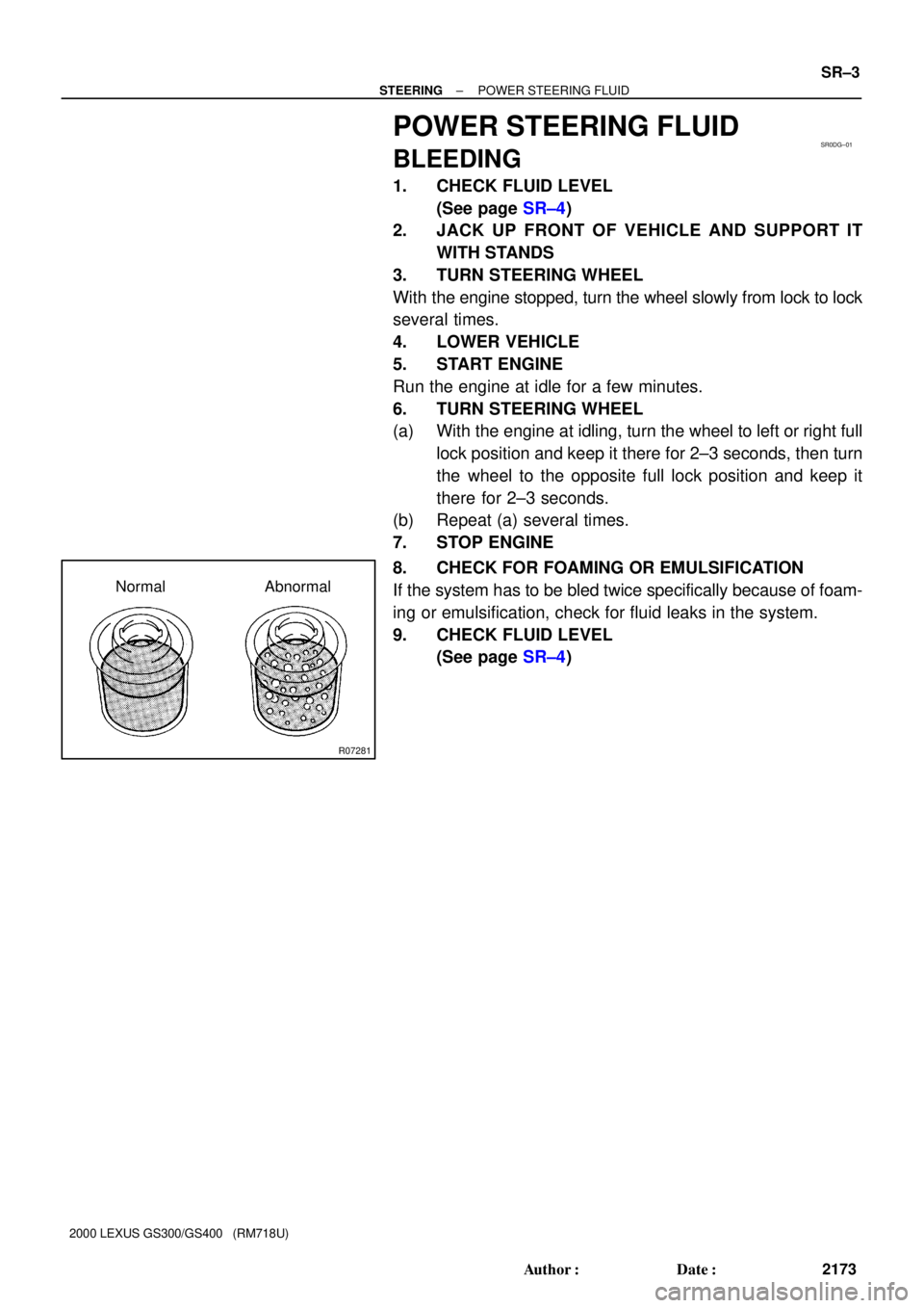
Normal Abnormal
± STEERINGPOWER STEERING FLUID
SR±3
2173 Author�: Date�:
2000 LEXUS GS300/GS400 (RM718U)
POWER STEERING FLUID
BLEEDING
1. CHECK FLUID LEVEL
(See page SR±4)
2. JACK UP FRONT OF VEHICLE AND SUPPORT IT
WITH STANDS
3. TURN STEERING WHEEL
With the engine stopped, turn the wheel slowly from lock to lock
several times.
4. LOWER VEHICLE
5. START ENGINE
Run the engine at idle for a few minutes.
6. TURN STEERING WHEEL
(a) With the engine at idling, turn the wheel to left or right full
lock position and keep it there for 2±3 seconds, then turn
the wheel to the opposite full lock position and keep it
there for 2±3 seconds.
(b) Repeat (a) several times.
7. STOP ENGINE
8. CHECK FOR FOAMING OR EMULSIFICATION
If the system has to be bled twice specifically because of foam-
ing or emulsification, check for fluid leaks in the system.
9. CHECK FLUID LEVEL
(See page SR±4)