Page 489 of 1111
B02035
ECT Switch
Connector
ECT
Switch
O±Ring
CO0AJ±01
P05962
Ohmmeter
± COOLING (2JZ±GE)ENGINE COOLANT TEMPERATURE (ECT) SWITCH
CO±31
1569 Author�: Date�:
2000 LEXUS GS300/GS400 (RM718U)
ENGINE COOLANT
TEMPERATURE (ECT) SWITCH
INSPECTION
1. DRAIN ENGINE COOLANT
2. REMOVE ECT SWITCH
(a) Disconnect the connector.
(b) Remove the ECT switch.
(c) Remove the O±ring from the ECT switch.
3. INSPECT ECT SWITCH
(a) Using an ohmmeter, check that there is no continuity be-
tween the terminals when the coolant temperature is
above 93°C (199°F).
If there is continuity, replace the switch.
(b) Using an ohmmeter, check that there is continuity be-
tween the terminals when the coolant temperature is be-
low 83°C (181°F).
If there is no continuity, replace the switch.
4. REINSTALL ECT SWITCH
(a) Install a new O±ring to the ECT switch.
(b) Install the ECT switch.
(c) Connect the connector.
5. REFILL WITH ENGINE COOLANT
6. START ENGINE AND CHECK FOR COOLANT LEAKS
Page 519 of 1111
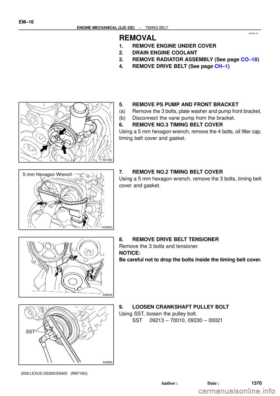
EM0D6±04
A01482
A02663
5 mm Hexagon Wrench
A02649
A02690
SST
EM±16
± ENGINE MECHANICAL (2JZ±GE)TIMING BELT
1370 Author�: Date�:
2000 LEXUS GS300/GS400 (RM718U)
REMOVAL
1. REMOVE ENGINE UNDER COVER
2. DRAIN ENGINE COOLANT
3. REMOVE RADIATOR ASSEMBLY (See page CO±18)
4. REMOVE DRIVE BELT (See page CH±1)
5. REMOVE PS PUMP AND FRONT BRACKET
(a) Remove the 3 bolts, plate washer and pump front bracket.
(b) Disconnect the vane pump from the bracket.
6. REMOVE NO.3 TIMING BELT COVER
Using a 5 mm hexagon wrench, remove the 4 bolts, oil filler cap,
timing belt cover and gasket.
7. REMOVE NO.2 TIMING BELT COVER
Using a 5 mm hexagon wrench, remove the 3 bolts, timing belt
cover and gasket.
8. REMOVE DRIVE BELT TENSIONER
Remove the 3 bolts and tensioner.
NOTICE:
Be careful not to drop the bolts inside the timing belt cover.
9. LOOSEN CRANKSHAFT PULLEY BOLT
Using SST, loosen the pulley bolt.
SST 09213 ± 70010, 09330 ± 00021
Page 531 of 1111
TIMING BELT
1382 Author�: Date�:
2000 LEXUS GS300/GS400 (RM718U)
20. INSTALL NO.2 TIMING BELT COVER
(a) Install the gasket on the timing")
A02803Plate Washer
A
B
A EM±28
± ENGINE MECHANICAL (2JZ±GE)TIMING BELT
1382 Author�: Date�:
2000 LEXUS GS300/GS400 (RM718U)
20. INSTALL NO.2 TIMING BELT COVER
(a) Install the gasket on the timing belt cover.
(b) Using a 5 mm hexagon wrench, install the timing belt cov-
er with the 3 bolts.
Torque: 8.0 N´m (80 kgf´cm, 71 in.´lbf)
21. INSTALL NO.3 TIMING BELT COVER
(a) Install the gasket on the timing belt cover.
(b) Using a 5 mm hexagon wrench, install the timing belt cov-
er with the 4 bolts.
Torque: 8.0 N´m (80 kgf´cm, 71 in.´lbf)
(c) Install the oil filler cap.
22. INSTALL PS PUMP AND FRONT BRACKET
(a) Temporarily install the vane pump to the bracket.
(b) Install the plate washer and front bracket with the 3 bolts.
Torque: 58 N´m (590 kgf´cm, 43 ft´lbf) for A bolts
52 N´m (530 kgf´cm, 38 ft´lbf) for B bolt
23. INSTALL DRIVE BELT (See page CH±1)
24. INSTALL RADIATOR ASSEMBLY (See page CO±23)
25. FILL ENGINE WITH COOLANT
26. START ENGINE CHECK FOR LEAKS
27. INSTALL ENGINE UNDER COVER
28. ROAD TEST
Check for abnormal noise, shock, slippage, correct shift points
and smooth operation.
29. RECHECK ENGINE COOLANT LEVEL
Page 538 of 1111
CYLINDER HEAD
EM±33
1387 Author�: Date�:
2000 LEXUS GS300/GS400 (RM718U)
REMOVAL
1. REMOVE ENGINE UNDER COVER
2. DRAI")
EM0DA±03
A02823
A02802
B01935
Wire
Grommet
Clamp
± ENGINE MECHANICAL (2JZ±GE)CYLINDER HEAD
EM±33
1387 Author�: Date�:
2000 LEXUS GS300/GS400 (RM718U)
REMOVAL
1. REMOVE ENGINE UNDER COVER
2. DRAIN ENGINE COOLANT
3. DISCONNECT UPPER RADIATOR HOSE FROM WA-
TER OUTLET
4. REMOVE ENGINE COVER
Remove the 4 nuts and engine cover.
5. REMOVE AIR CLEANER INLET
6. REMOVE AIR CLEANER, MAF METER AND INTAKE
AIR RESONATOR ASSEMBLY (See page EM±62)
7. REMOVE DRIVE BELT (See page CH±1)
8. DISCONNECT PS PUMP WITHOUT DISCONNECTING
HOSES
(a) Disconnect the PS air hose from the No.4 timing belt cov-
er.
(b) Disconnect the PS air hose from the air intake chamber.
(c) Remove the 2 bolts and pump rear stay.
(d) Remove the 2 bolts, and disconnect the vane pump from
the pump bracket.
HINT:
Put aside the vane pump, and suspend it.
9. DISCONNECT FRONT EXHAUST PIPE FROM EX-
HAUST MANIFOLD
(a) Disconnect the wire grommet and sensor wire of the
heated oxygen sensor (bank 2 sensor 2) from the hole
and clamp on the floor.
Page 555 of 1111
 (g)
(f)
(e) (b)
(c)
A11130
(h)(i)
(j)
(k)
A11129
(o)
(n)
(o)
± ENGINE MECHANICAL (2JZ±GE)VALVE CLEARANCE
EM±5
1359 Author�: Date�:
2000 LEXUS GS300/GS400 (RM718U)
VALVE CLEAR")
EM0D2±04
A11131
(d) (g)
(f)
(e) (b)
(c)
A11130
(h)(i)
(j)
(k)
A11129
(o)
(n)
(o)
± ENGINE MECHANICAL (2JZ±GE)VALVE CLEARANCE
EM±5
1359 Author�: Date�:
2000 LEXUS GS300/GS400 (RM718U)
VALVE CLEARANCE
ADJUSTMENT
HINT:
Inspect and adjust the valve clearance when the engine is cold.
1. REMOVE ENGINE COVER
Remove the 4 nuts and engine cover.
2. DRAIN ENGINE COOLANT
3. REMOVE INTAKE AIR RESONATOR
4. REMOVE THROTTLE BODY AND INTAKE AIR
CONNECTOR ASSEMBLY
(a) Disconnect the accelerator cable from the throttle body.
(b) Disconnect the engine wire clamp from the clamp bracket
of the throttle body.
(c) Disconnect the engine wire from the clamp on the throttle
body bracket.
(d) Disconnect the accelerator pedal position sensor con-
nector.
(e) Disconnect the throttle control motor connector.
(f) Disconnect the throttle position sensor connector.
(g) Disconnect the air assist hose from the intake air connec-
tor.
(h) Disconnect the PCV hose from the intake air connector.
(i) Disconnect the VSV connector for EVAP.
(j) Disconnect the EVAP hose (from charcoal canister) from
the VSV for EVAP.
(k) Disconnect the vacuum hose (from No.2 vacuum pipe)
from the No.1 vacuum pipe.
(l) Remove the 2 nuts holding the throttle body bracket to the
cylinder head.
(m) Remove the 4 bolts and 2 nuts holding the intake air con-
nector to the air intake chamber.
(n) Disconnect the vacuum hose (from actuator for ACIS)
from the No.1 vacuum pipe.
(o) Disconnect the 2 water bypass hoses from the throttle
body, and remove the throttle body together with the in-
take air connector and gasket.
Page 559 of 1111
VALVE CLEARANCE
EM±9
1363 Author�: Date�:
2000 LEXUS GS300/GS400 (RM718U)
15. REINSTALL SPARK PLUGS
16. REINSTALL IGNITION COILS AND HIGH±TENSION
CORD SET ASSEMBLY (S")
± ENGINE MECHANICAL (2JZ±GE)VALVE CLEARANCE
EM±9
1363 Author�: Date�:
2000 LEXUS GS300/GS400 (RM718U)
15. REINSTALL SPARK PLUGS
16. REINSTALL IGNITION COILS AND HIGH±TENSION
CORD SET ASSEMBLY (See page IG±9)
17. REINSTALL NO.3 TIMING BELT COVER
(a) Install the gasket to the timing belt cover.
(b) Using a 5 mm hexagon wrench, install the timing belt cov-
er with the 4 bolts.
Torque: 8.0 N´m (80 kgf´cm, 71 in.´lbf)
(c) Install the oil filler cap.
18. REINSTALL THROTTLE BODY AND INTAKE AIR CON-
NECTOR ASSEMBLY
(a) Install a new gasket to the air intake chamber.
(b) Place the throttle body together with the intake air con-
nector on the cylinder head.
(c) Connect the vacuum hose (from actuator for ACIS) to the
No.1 vacuum pipe.
(d) Connect the 2 water bypass hoses to the throttle body.
(e) Install the 4 bolts and 2 nuts holding the intake air connec-
tor to the air intake chamber.
Torque: 28 N´m (280 kgf´cm, 21 ft´lbf)
(f) Install the 2 nuts holding the throttle body bracket to the
cylinder head.
Torque: 21 N´m (210 kgf´cm, 15 ft´lbf)
(g) Connect the air assist hose to the intake air connector.
(h) Install the PCV hose to the intake air connector.
(i) Install the EVAP hose (from charcoal canister) to the VSV
for EVAP.
(j) Install the vacuum hose (from No.2 vacuum pipe) to the
No.1 vacuum pipe.
(k) Install the throttle position sensor connector.
(l) Install the accelerator pedal position sensor connector.
(m) Install the throttle control motor connector.
(n) Install the VSV connector for EVAP.
(o) Secure the engine wire with the clamp on the throttle body
bracket.
(p) Install the engine wire clamp with the clamp bracket of the
throttle body.
(q) Connect the accelerator cable to the throttle body.
19. REINSTALL INTAKE AIR RESONATOR
20. REINSTALL ENGINE COVER
Install the engine cover with the 4 nuts.
21. REFILL WITH ENGINE COOLANT
22. START ENGINE AND CHECK FOR LEAKS
Page 570 of 1111
CYLINDER HEAD
1412 Author�: Date�:
2000 LEXUS GS300/GS400 (RM718U)
Torque: 44 N´m (440 kgf´cm, 32 ft´lbf)
(d) Connect the wi")
B01935
Wire
Grommet
Clamp
A02802
EM±58
± ENGINE MECHANICAL (2JZ±GE)CYLINDER HEAD
1412 Author�: Date�:
2000 LEXUS GS300/GS400 (RM718U)
Torque: 44 N´m (440 kgf´cm, 32 ft´lbf)
(d) Connect the wire grommet and sensor wire of the the
heated oxygen sensor (bank 2 sensor 2) to the hole and
clamp on the floor.
23. INSTALL PS PUMP
(a) Install the vane pump with the 2 bolts.
Torque: 58 N´m (590 kgf´cm, 43 ft´lbf)
(b) Install the pump rear stay with the 2 bolts.
Torque: 39.2 N´m (400 kgf´cm, 29 ft´lbf)
(c) Connect the PS air hose to the No.4 timing belt cover.
(d) Connect the PS air hose to the air intake chamber.
24. INSTALL DRIVE BELT (See page CH±1)
25. INSTALL AIR CLEANER, MAF METER AND INTAKE
AIR RESONATOR ASSEMBLY (See page EM±68)
26. INSTALL AIR CLEANER INLET
27. CONNECT UPPER RADIATOR HOSE TO WATER OUT-
LET
28. INSTALL ENGINE COVER
Install the engine cover with the 4 nuts.
29. FILL WITH ENGINE COOLANT
30. START ENGINE AND CHECK FOR LEAKS
31. INSTALL ENGINE UNDER COVER
32. ROAD TEST
Check for abnormal noise, shock, slippage, correct shift points
and smooth operation.
33. RECHECK ENGINE COOLANT LEVEL
Page 574 of 1111
ENGINE UNIT
1416 Author�: Date�:
2000 LEXUS GS300/GS400 (RM718U)
REMOVAL
1. REMOVE HOOD
NOTICE:
Be ca")
EM0DH±05
A02753
EVAP
Hose
Clamp
MAF Meter
Connector
A02751
EM±62
± ENGINE MECHANICAL (2JZ±GE)ENGINE UNIT
1416 Author�: Date�:
2000 LEXUS GS300/GS400 (RM718U)
REMOVAL
1. REMOVE HOOD
NOTICE:
Be careful not to damage the body or glass with the hood
end.
2. REMOVE ENGINE UNDER COVER
3. DRAIN ENGINE COOLANT
4. DRAIN ENGINE OIL
5. REMOVE ENGINE COVER
Remove the 4 nuts and engine cover.
6. REMOVE AIR CLEANER INLET
7. REMOVE AIR CLEANER, MAF METER AND INTAKE
AIR RESONATOR ASSEMBLY
(a) Disconnect the MAF meter connector.
(b) Disconnect the engine wire clamp from the air cleaner
case.
(c) Disconnect the EVAP hose from the air cleaner case.
(d) Disconnect the PS air hose from the No.4 timing belt cov-
er.
(e) Disconnect the PCV hose from the No.2 cylinder head
cover.
(f) Loosen the hose clamp bolt holding the intake air resona-
tor to the throttle body.
(g) Remove the 3 bolts, the air cleaner, MAF meter and intake
air resonator assembly.
8. DISCONNECT ACCELERATOR CABLE FROM EN-
GINE
9. REMOVE RADIATOR ASSEMBLY (See page CO±18)
10. REMOVE DRIVE BELT (See page CH±1)
11. REMOVE FRONT SUSPENSION MEMBER BRACE
Remove the 6 bolts and brace.