Page 366 of 1111
I04250
� Combination Meter Wiring Circuit ± 1
:Speedometer
:Tachometer
:Fuel Receiver Gauge
:Engine Coolant
Temperature
Receiver Gauge
Speed Control Unit
CLOCK
to GAUGE Fuse
to MPX±B Fuse
to SRS Fuse
Tilt and Telescopic ECU
Body ECU NO.2ECM (GS400)
Ignitor (GS300)
Fuel Main Sender GaugeGround
Fuel Sub Sender Gauge
Light Control Rheostat
Illuminations
ABS, TRAC and VSC ECU
ABS, TRAC and VSC ECU Speed Signal Passenger seat
belt warning
Rr LIGHTS
SEAT BELT
OIL PRESS
OIL LEVEL
DOOR IG+
SRS +BA/T P
A/T R
A/T N
A/T D
A/T 4
A/T 3
A/T 2
A/T L
CRUISE MPX+BIG+IG+
5V
+B
to ECUto
PANEL
Fuse B4
B5
B6
B9
A5
A17A3A8 B16
LCDECU S
T
F
E
Power Source
Brake
Buzzer A11A2 A1 A6
B1
B13
B14A4
B22 ECU
ECU
ECU
S
T
F
E
CHARGE
FUEL LVL
ECT PWR
ECT SNOW TAIL or HEAD
Ground IG+IG+ IG+ IG+
+B
± BODY ELECTRICALCOMBINATION METER
BE±83
2384 Author�: Date�:
2000 LEXUS GS300/GS400 (RM718U)
Page 370 of 1111
I04252
Engine
Coolant
Temperature
Receiver
Gauge
Tachometer
Speedometer
Fuel
Receiver
GaugeRight Turn Indicator Left Turn Indicator
ODO/TRIP Switch
RESET Switch TECOS+
TESIN+
TECOS± TESIN±
TACOS+
TASIN±
TASIN+
TACOS±
SPCOS±
SPSIN+
SPSIN±
SPCOS+
FUCOS±
FUSIN+TURN L
Power
Earth
TURN R
ODO/TRIP
RESET
HEAT±
Signal
Earth
Thermistor
SRS +B
C/C ±
C/C +
HEAT±
SRS +B Power
Earth O1
O2
O3
O4
P1
P2
P3
P4
Q1
Q2
Q3
Q4
R1
R2
R3G2 G1
G3
G4
G5
G6
G7
G8
L1
L2
L3
L4
L8
L12
K1
K3
K4
R4FUSIN±
FUCOS+C/C ±
C/C +K8
K12 Combination Meter ECU � Meter Circuit Plate ± 1
± BODY ELECTRICALCOMBINATION METER
BE±87
2388 Author�: Date�:
2000 LEXUS GS300/GS400 (RM718U)
Page 372 of 1111
BE0HJ±08
I04254
Meter Glass Decoration Plate Fuel Receiver Gauge
and Engine Coolant
Temperature Gauge SpeedometerTachometer
Cold Cathode Tube with PlateMeter Body ECU Plate Meter Cover
Buzzer
Telltale Light Assembly Connector
Clips
± BODY ELECTRICALCOMBINATION METER
BE±89
2390 Author�: Date�:
2000 LEXUS GS300/GS400 (RM718U)
COMPONENTS
Page 374 of 1111
I04259
I04260
I04261
I04262
I04263
± BODY ELECTRICALCOMBINATION METER
BE±91
2392 Author�: Date�:
2000 LEXUS GS300/GS400 (RM718U)
5. REMOVE METER GLASS
Remove the 3 screws and the meter glass.
6. REMOVE DECORATION PLATE
7. REMOVE SPEEDOMETER
Remove the 2 screws.
8. REMOVE TACHOMETER, FUEL RECEIVER GAUGE
AND ENGINE COOLANT TEMPERATURE RECEIVER
GAUGE
Remove the 4 screws.
9. REMOVE COLD CATHODE TUBE WITH PLATE
Page 377 of 1111

I04080
Connector
ºOº, ºPº, ºQº, ºRº BE±94
± BODY ELECTRICALCOMBINATION METER
2395 Author�: Date�:
2000 LEXUS GS300/GS400 (RM718U)F5 (±) ± F12 (+)
A/T shift indicator light (R)Continuity
F2 (±) ± F12 (+)A/T shift indicator light (N)Continuity
F1 (±) ± F12 (+)A/T shift indicator light (D)Continuity
G1 (+) ± G5 (±)Left turn signal indicator lightContinuity
G6 (+) ± G5 (±)Right turn signal indicator lightContinuity
If circuit is not as specified, replace the bulb or circuit plate.
3. INSPECT COMBINATION METER CIRCUIT PLATE
From combination meter ECU to gauges:
TerminalResistance (W)
O1 ± O3
(Engine coolant temperature receiver gauge)Approx. 164.2
O2 ± O4
(Engine coolant temperature receiver gauge)Approx. 151.8
P1 ± P4 (Tachometer)Approx. 164.2
P2 ± P3 (Tachometer)Approx. 151.8
Q1 ± Q4 (Speedometer)Approx. 164.2
Q2 ± Q3 (Speedometer)Approx. 151.8
R1 ± R4 (Fuel receiver gauge)Approx. 164.2
R2 ± R3 (Fuel receiver gauge)Approx. 151.8
If circuit is not as specified, inspect the gauge or meter.
Then recheck system.
If circuit is not as specified, replace the circuit plate.
Page 381 of 1111

I04091
F
E1
2
1/2
I04094
A
D
C
B
I01277
Battery Ignition
SwitchWarning Light
Wire Harness Side
1 BE±98
± BODY ELECTRICALCOMBINATION METER
2399 Author�: Date�:
2000 LEXUS GS300/GS400 (RM718U)
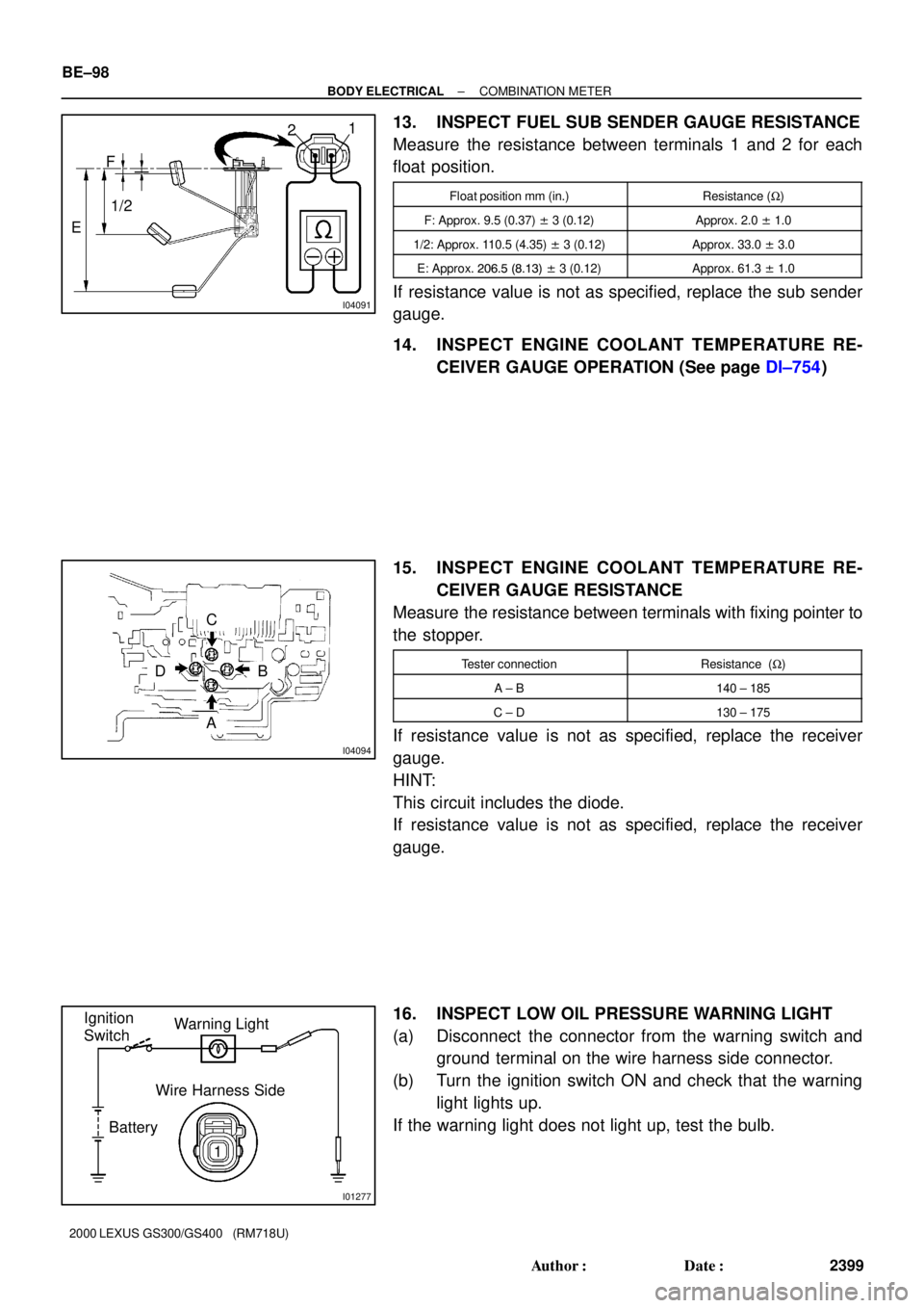
13. INSPECT FUEL SUB SENDER GAUGE RESISTANCE
Measure the resistance between terminals 1 and 2 for each
float position.
Float position mm (in.)Resistance (W)
F: Approx. 9.5 (0.37) ± 3 (0.12)Approx. 2.0 ± 1.0
1/2: Approx. 110.5 (4.35) ± 3 (0.12)Approx. 33.0 ± 3.0
E: Approx. 206.5 (8.13) ± 3 (0.12)Approx. 61.3 ± 1.0
If resistance value is not as specified, replace the sub sender
gauge.
14. INSPECT ENGINE COOLANT TEMPERATURE RE-
CEIVER GAUGE OPERATION (See page DI±754)
15. INSPECT ENGINE COOLANT TEMPERATURE RE-
CEIVER GAUGE RESISTANCE
Measure the resistance between terminals with fixing pointer to
the stopper.
Tester connectionResistance (W)
A ± B140 ± 185
C ± D130 ± 175
If resistance value is not as specified, replace the receiver
gauge.
HINT:
This circuit includes the diode.
If resistance value is not as specified, replace the receiver
gauge.
16. INSPECT LOW OIL PRESSURE WARNING LIGHT
(a) Disconnect the connector from the warning switch and
ground terminal on the wire harness side connector.
(b) Turn the ignition switch ON and check that the warning
light lights up.
If the warning light does not light up, test the bulb.
Page 464 of 1111
CO09W±03
± COOLING (2JZ±GE)COOLANT
CO±1
1539 Author�: Date�:
2000 LEXUS GS300/GS400 (RM718U)
COOLANT
INSPECTION
1. CHECK ENGINE COOLANT LEVEL AT RESERVOIR
The engine coolant level should be between the ºLOWº and ºFULLº lines, when the engine is cold.
If low, check for leaks and add ºToyota Long Life Coolantº or equivalent up to the ºFULLº line.
2. CHECK ENGINE COOLANT QUALITY
There should not be any excessive deposits of rust or scale around the radiator cap or radiator filler hole,
and the coolant should be free from oil.
If excessively dirty, replace the coolant.
Page 466 of 1111
CO0A3±01
B01940
± COOLING (2JZ±GE)THERMOSTAT
CO±11
1549 Author�: Date�:
2000 LEXUS GS300/GS400 (RM718U)
REMOVAL
HINT:
Removal of the thermostat would have an adverse effect, caus-
ing a lowering of cooling efficiency. Do not remove the thermo-
stat, even if the engine tends to overheat.
1. DRAIN ENGINE COOLANT
2. DISCONNECT WATER INLET FROM WATER PUMP,
AND REMOVE THERMOSTAT
(a) Remove the 2 nuts holding the water inlet to the water
pump, and disconnect the water inlet from the water
pump.
(b) Remove the thermostat.
(c) Remove the gasket from the thermostat.