Page 428 of 1111

AIR BLEED
FRONT
REARActuator Checker (SST) BR±6
± BRAKEBRAKE FLUID
2114 Author�: Date�:
2000 LEXUS GS300/GS400 (RM718U)
(b) Connect the act")
F02821
Hydraulic Brake
BoosterSub±Wire harness S (SST)
AIR BLEED
FRONT
REARActuator Checker (SST) BR±6
± BRAKEBRAKE FLUID
2114 Author�: Date�:
2000 LEXUS GS300/GS400 (RM718U)
(b) Connect the actuator checker (SST) to the hydraulic
brake booster side wire harness via the sub±wire harness
S (SST), as shown in the chart below.
SST 09990±00150, 09990±00480
HINT:
Connect the connector with the label of ºAIR BLEEDº attached
to the connector of actuator checker.
(c) Connect the red cable of the actuator checker to the bat-
tery positive (+) terminal and the black cable to the nega-
tive (±) terminal.
(d) Turn the ignition switch OFF, depress the brake pedal
more than 40 times.
HINT:
When a pressure in power supply system is released, reaction
force becomes heavy and stroke becomes shorter.
(e) Turn the ignition switch ON, check that the pump stops af-
ter approx. 30 to 40 seconds.
NOTICE:
When the pump does not stop, repeat step (d) and (e) again.
(f) With the ignition switch remained ON, depress the brake
pedal more than 20 times.
(g) Observe the procedure in step 4 and bleed the right and
left front wheel caliper.
(h) Holding the brake pedal depressed, bleed the right and
left rear wheel caliper.
HINT:
It is not necessary to depress the pedal continuously, as brake
fluid flows out by first depressing.
Page 429 of 1111

(i) Bleed right front brake line.
(1) Turn the selector switch of the actuator checker to
the ºFR")
F02823
F02824
F02825
± BRAKEBRAKE FLUID
BR±7
2115 Author�: Date�:
2000 LEXUS GS300/GS400 (RM718U)
(i) Bleed right front brake line.
(1) Turn the selector switch of the actuator checker to
the ºFRONT RHº position.
(2) Push and hold in MAIN push switch, depress the
brake pedal and hold it to bleed the right front brake
caliper.
NOTICE:
Do not keep the MAIN switch pushed in for more than 10 se-
conds. When operating it continuously, set the interval of
more than 20 seconds.
(3) Repeat step (2) until there are no more air bubbles
in the fluid.
(j) Bleed left front brake line.
(1) Turn the selector switch of the actuator checker to
the ºFRONT LHº position.
(2) Push and hold in the MAIN push switch, depress the
brake pedal and hold it to bleed the left front brake
caliper.
NOTICE:
Do not keep the MAIN switch pushed in for more than 10 se-
conds. When operating it continuously, set the interval of
more than 20 seconds.
(3) Repeat step (2) until there are no more air bubbles
in the fluid.
(k) Bleed right rear brake line.
(1) Push and hold in the ºSUB LHº and ºSUB RHº
switches, bleed the right rear brake caliper.
NOTICE:
Do not keep the MAIN switch pushed in for more than 10 se-
conds. When operating it continuously, set the interval of
more than 20 seconds.
(2) Repeat step (1) until there are no more air bubbles
in the fluid.
Page 430 of 1111

(l) Observe the procedure in step (k) and bleed left rear
brake line.
(m) Disconnect the actuator checker (SST)")
F02851
BR±8
± BRAKEBRAKE FLUID
2116 Author�: Date�:
2000 LEXUS GS300/GS400 (RM718U)
(l) Observe the procedure in step (k) and bleed left rear
brake line.
(m) Disconnect the actuator checker (SST) and sub±wire har-
ness (SST) from the actuator.
SST 09990±00150, 09990±00480
(n) Connect the 2 connectors to the hydraulic brake booster.
(o) Clear the DTC (See page DI±389).
4. BLEED BRAKE LINE
(a) Connect the vinyl tube to the brake caliper.
(b) Depress the brake pedal several times, then loosen the
bleeder plug with the pedal held down.
(c) At the point when fluid stops coming out, tighten the
bleeder plug, then release the brake pedal.
(d) Repeat (b) and (c) until all the air in the fluid has been bled
out.
(e) Repeat the above procedure to bleed the brake line for
each wheel.
Torque: 11 N´m (110 kgf´cm, 8 ft´lbf)
5. CHECK FLUID LEVEL IN RESERVOIR
(a) With the ignition switch OFF, depress the brake pedal
more than 40 times.
HINT:
When a pressure in power supply system is released, reaction
force becomes heavy and stroke becomes shorter.
(b) Remove the reservoir cap. Add brake fluid up to the
ºMAXº line.
Fluid: SAE J1703 or FMVSS NO. 116 DOT3
Page 431 of 1111
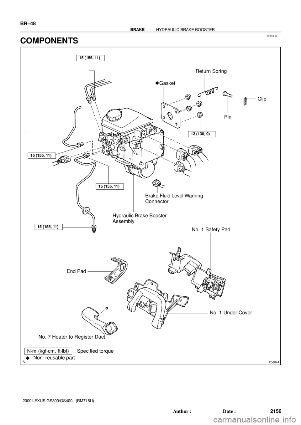
BR0K8±09
F06044Non±reusable part
��Gasket
Hydraulic Brake Booster
Assembly
13 (130, 9)
End PadBrake Fluid Level Warning
ConnectorReturn Spring
No. 7 Heater to Register DuctNo. 1 Under Cover No. 1 Safety Pad
15 (155, 11)
15 (155, 11)
15 (155, 11)
15 (155, 11)
N´m (kgf´cm, ft´lbf) : Specified torquePin
Clip BR±48
± BRAKEHYDRAULIC BRAKE BOOSTER
2156 Author�: Date�:
2000 LEXUS GS300/GS400 (RM718U)
COMPONENTS
Page 433 of 1111

REMOVAL
NOTICE:
�Before starting the work, make sure that the ignit")
BR0K9±04
F06046
SST
F01655
SST
F06047
BR±50
± BRAKEHYDRAULIC BRAKE BOOSTER
2158 Author�: Date�:
2000 LEXUS GS300/GS400 (RM718U)
REMOVAL
NOTICE:
�Before starting the work, make sure that the ignition
switch is OFF and depress the brake pedal more than
40 times.
�As high pressure is applied to the brake actuator tube
No. 1, never deform it.
�Until the work is over, do not turn the ignition switch
ON.
1. DRAW OUT FLUID WITH SYRINGE
NOTICE:
Do not let brake fluid remain on a painted surface. Wash it
off immediately.
2. REMOVE NO. 1 UNDER COVER (See page BO±88)
3. REMOVE END PAD AND NO. 1 SAFETY PAD
4. REMOVE NO. 7 HEATER TO REGISTER DUCT
5. DISCONNECT BRAKE LINES
Using SST, disconnect the 4 brake lines.
SST 09023±00100
Torque: 15 N´m (155 kgf´cm, 11 ft´lbf)
6. DISCONNECT LEFT FRONT WHEEL BRAKE LINE
Using SST, disconnect the left front wheel brake line from the
flexible hose.
SST 09023±00100
Torque: 15 N´m (155 kgf´cm, 11 ft´lbf)
7. REMOVE 2 BRAKE LINE CLAMPS
8. DISCONNECT LEVEL WARNING SWITCH CONNEC-
TOR
9. DISCONNECT 4 CONNECTORS
10. REMOVE PEDAL RETURN SPRING, CLIP AND CLE-
VIS PIN
11. REMOVE HYDRAULIC BRAKE BOOSTER ASSEMBLY
(a) Loosen the lock nut, then remove the clevis and lock nut.
Torque: 25 N´m (260 kgf´cm, 19 ft´lbf)
(b) Remove the 4 booster installation nuts.
Torque: 13 N´m (130 kgf´cm, 9 ft´lbf)
(c) Remove the booster assembly and gasket.
Page 439 of 1111
BR0KD±05
BR±56
± BRAKEHYDRAULIC BRAKE BOOSTER
2164 Author�: Date�:
2000 LEXUS GS300/GS400 (RM718U)
INSTALLATION
Installation is in the reverse order of removal (See page BR±50).
HINT:
�After installation, fill the brake reservoir with brake fluid and bleed brake system (See page BR±4).
�Check for leaks.
Page 639 of 1111

TERMS
ABBREVIATIONS USED IN THIS MANUAL
AbbreviationsMeaning
ABSAnti±Lock Brake System
ACAlternating Current")
IN04Q±07
IN±36
± INTRODUCTIONTERMS
36 Author�: Date�:
2000 LEXUS GS300/GS400 (RM718U)
TERMS
ABBREVIATIONS USED IN THIS MANUAL
AbbreviationsMeaning
ABSAnti±Lock Brake System
ACAlternating Current
ACCAccessory
ACISAcoustic Control Induction System
ACSDAutomatic Cold Start Device
A.D.D.Automatic Disconnecting Differential
A/FAir±Fuel Ratio
AHCActive Height Control Suspension
ALRAutomatic Locking Retractor
ALTAlternator
AMPAmplifier
ANTAntenna
APPROX.Approximately
A/TAutomatic Transmission (Transaxle)
AT FAutomatic Transmission Fluid
AUTOAutomatic
AUXAuxiliary
AV GAverage
AV SAdaptive Variable Suspension
BABrake Assist
BACSBoost Altitude Compensation System
BATBattery
BDCBottom Dead Center
B/LBi±Level
B/SBore±Stroke Ratio
BTDCBefore Top Dead Center
BVSVBimetallic Vacuum Switching Valve
Calif.California
CBCircuit Breaker
CCoCatalytic Converter For Oxidation
CDCompact Disc
CFCornering Force
CGCenter Of Gravity
CHChannel
COMB.Combination
CPECoupe
CPSCombustion Pressure Sensor
CPUCentral Processing Unit
CRSChild Restraint System
CTRCenter
C/VCheck Valve
CVControl Valve
Page 671 of 1111

UNDER HOOD
GENERAL MAINTENANCE
1. GENERAL NOTES
�Maintenance items may vary from country to country. Chec")
MA003±06
MA±4
± MAINTENANCEUNDER HOOD
47 Author�: Date�:
2000 LEXUS GS300/GS400 (RM718U)
UNDER HOOD
GENERAL MAINTENANCE
1. GENERAL NOTES
�Maintenance items may vary from country to country. Check the owner's manual supplement in which
the maintenance schedule is shown.
�Every service item in the periodic maintenance schedule must be performed.
�Periodic maintenance service must be performed according to whichever interval in the periodic main-
tenance schedule occurs first, the odometer reading (miles) or the time interval (months).
�Maintenance service after the last period should be performed at the same interval as before unless
otherwise noted.
�Failure to do even one item an cause the engine to run poorly and increase exhaust emissions.
2. WINDSHIELD WASHER FLUID
Check that there is sufficient fluid in the tank.
3. ENGINE COOLANT LEVEL
Check that the coolant level is between the ºFULLº and ºLOWº lines on the see±through reservoir.
4. RADIATOR AND HOSES
(a) Check that the front of the radiator is clean and not blocked with leaves, dirt or bugs.
(b) Check the hoses for cracks, kinks, rot or loose connections.
5. BATTERY ELECTROLYTE LEVEL
Check that the electrolyte level of all battery cells is between the upper and lower level lines on the case.
6. BRAKE FLUID LEVEL
Check that the brake fluid levels are near the upper level line on the see±through reservoirs.
7. ENGINE DRIVE BELT
Check drive belt for fraying, cracks, wear or oiliness.
8. ENGINE OIL LEVEL
Check the level on the dipstick with the engine turned off.
9. POWER STEERING FLUID LEVEL
�Check the level on the dipstick.
�The level should be in the ºHOTº or ºCOLDºrange depending on the fluid temperature.
10. AUTOMATIC TRANSMISSION FLUID LEVEL
(a) Park the vehicle on a level surface.
(b) With the engine idling and the parking brake applied, shift the selector into all positions from ºPº to ºLº,
and then shift into ºPº position.
(c) Pull out the dipstick and wipe off the fluid with a clean rag. Re±insert the dipstick and check that the
fluid level is in the HOT range.
(d) Do this check with the fluid at normal driving temperature (70 ± 80°C, 158 ± 176°F).
HINT:
Wait until the engine cools down (approx. 30 min.) before checking the fluid level after extended driving at
high speeds, in hot weather, in heavy traffic or pulling a trailer.
11. EXHAUST SYSTEM
If any change in the sound of the exhaust or smell of the exhaust fumes is noticed, have the cause located
and corrected.