2000 HONDA CR-V Connection
[x] Cancel search: ConnectionPage 348 of 1395
PGM-FI System
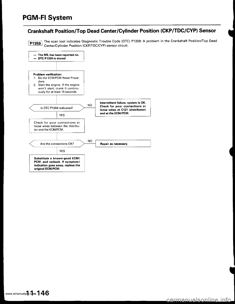
Crankshaft Position/Top Dead Center/Cylinder Position (CKP/TDC/CYP) Sensor
The scan tool indicates Diagnostic Trouble Code (DTC)
Center/Cvlinder Position tCKP/TDC/CYP) sensor circuit.
P1359:A problem in the Crankshaft Position/Top Dead
- The MIL has been reoorted on.- DTC P1359 is stored.
Problem verific.tion:1. Do the ECM/PCM Reset Proce-dure.2. Start the engine. lf the enginewon't start, crank it continu-ouslyfor at least 15 seconds.
Intermitteni lailure, system is OK.Check for ooor connections orloos€ wires al C121 {distributor}and at the ECM/PCM.
ls DTC P1359 indicated?
Check for poor connections orloose wires between the distribu'tor and the EcM/PcM.
Substitute a known-good ECM/PCM, and recheck. ll symplom/indication goes away, replace theoriginal ECM/PCM.
11-146
www.emanualpro.com
Page 377 of 1395
Fuel Tube/Ouick-Gonnect Fittings
Procautions
@ Do not smoke whils working on the fuel
syst6m, Koop open flames away from your work ar9a.
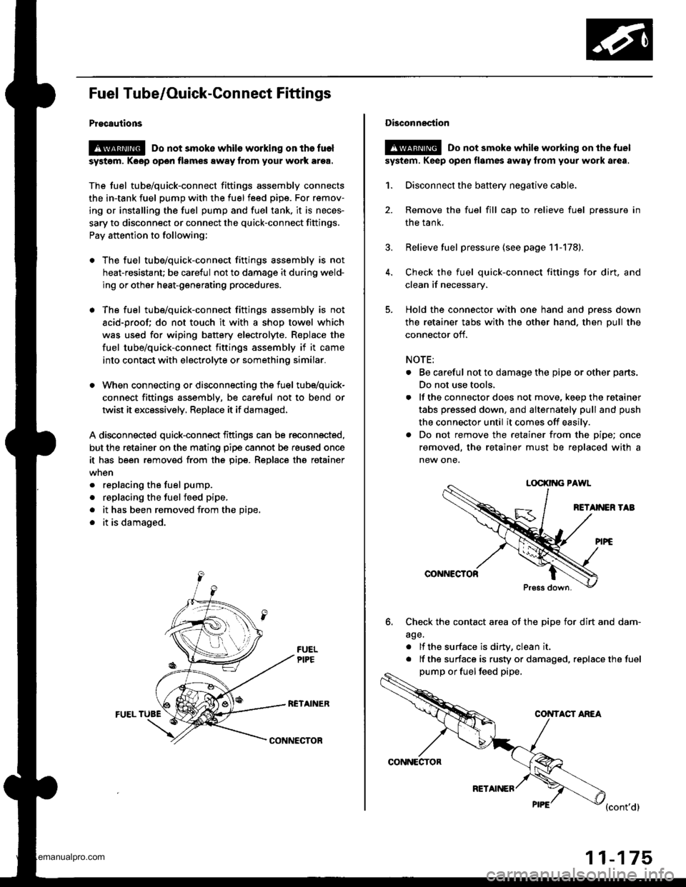
The fuel tube/quick-connect fittings assembly connects
the in-tank fuel pump with the fuel feed pipe. For remov-
ing or installing the fuel pump and fuel tank, it is neces-
sary to disconnect or connect the quick-connect fittings.
Pay attention to following;
. The fuel tube/quick-connect fittings assembly is not
heat-resistant; be careful not to damage it during weld-
ing or other heat-generating procedures.
. The fuel tube/quick-connect fittings assembly is not
acid-proof; do not touch it with a shop towel which
was used for wiping battery electrolyte. R€place the
fuel tube/quick-connect fittings assembly if it came
into contact with electrolyte or somethino similar.
. When connecting or disconnecting the fuel tube/quick-
connect fittings assembly, be careful not to bend or
twist it excessively, Replace it if damaged,
A disconnected quick-connect fittings can be reconnected,
but the retainer on the mating pipe cannot be reused once
it has been removed from the pipe. Replace tha retainer
. replacing the fuel pump.
. replacing the fuelfeed pipe,
. it has been removed from the Dioe,
. it is damaged.
RCTAINERFUEL TUBE
CONNECTOR
CONNECTOR
RETAINER
11-175
Disconnection
!@ Do not smoke while working on the fuel
syst6m. Keep open flames away from your work area.
1. Disconnect the battery negative cable.
2. Remove the fuel fill cap to relieve fuel pressure in
the tank.
3. Relieve fuel pressure (see page 11-178).
4. Check the fuel quick-connect fittings for dirt, and
clean if necessary.
5. Hold the connector with one hand and press down
the retainer tabs with the other hand. then pull the
connector off.
NOTE:
. Be careful not to damage the pipe or other parts.
Do not use tools,
. lf the connector does not move, keep the retainer
tabs pressed down, and alternately pull and push
the connector until it comes off easily.
. Do not remove the retainer from the pipe; once
removed, the retainer must be replaced with a
new one.
LOCKII{G PAWL
RETANEN TAB
@NNCCTOR
Press down.
6. Check the contact area of the pipe for dirt and dam-
age.
. lf the surface is dirW, clean it
. lf the surface is rusty or damaged, replace the fuel
pump or fuel feed pipe,
CONTACT ANEA
{cont'd}
www.emanualpro.com
Page 378 of 1395
Fuel Supply System
Fuel Tube/Ouick-Connect Fittings {cont'd)
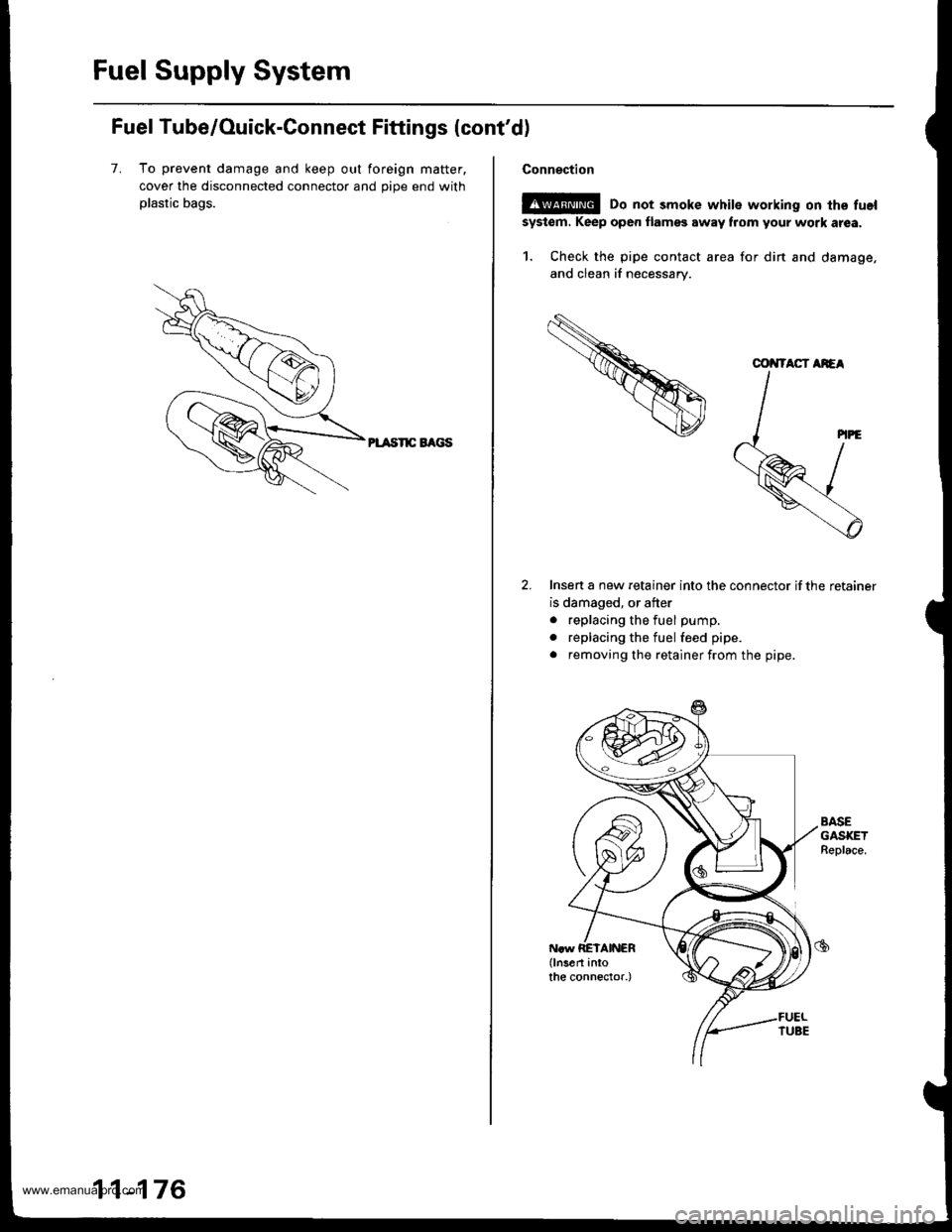
7. To prevent damage and keep out foreign matter.
cover the disconnected connector and oioe end with
plastic bags.
PL TSnC EAGS
11-176
Connection
E!@ Do not smoke white working on the fuel
system. Keep oper flamss away flom your work atea.
1. Check the pipe contact area for din and damage,
and clean if necessary.
Insen a new retainer into the connector if the retainer
is damaged, or after
. replacing the fuel pump.
. replacing the fuel feed pipe.
. removing the retainer from the pipe.
AASEGASKETBeplace.
COiITACT AiEA
www.emanualpro.com
Page 379 of 1395
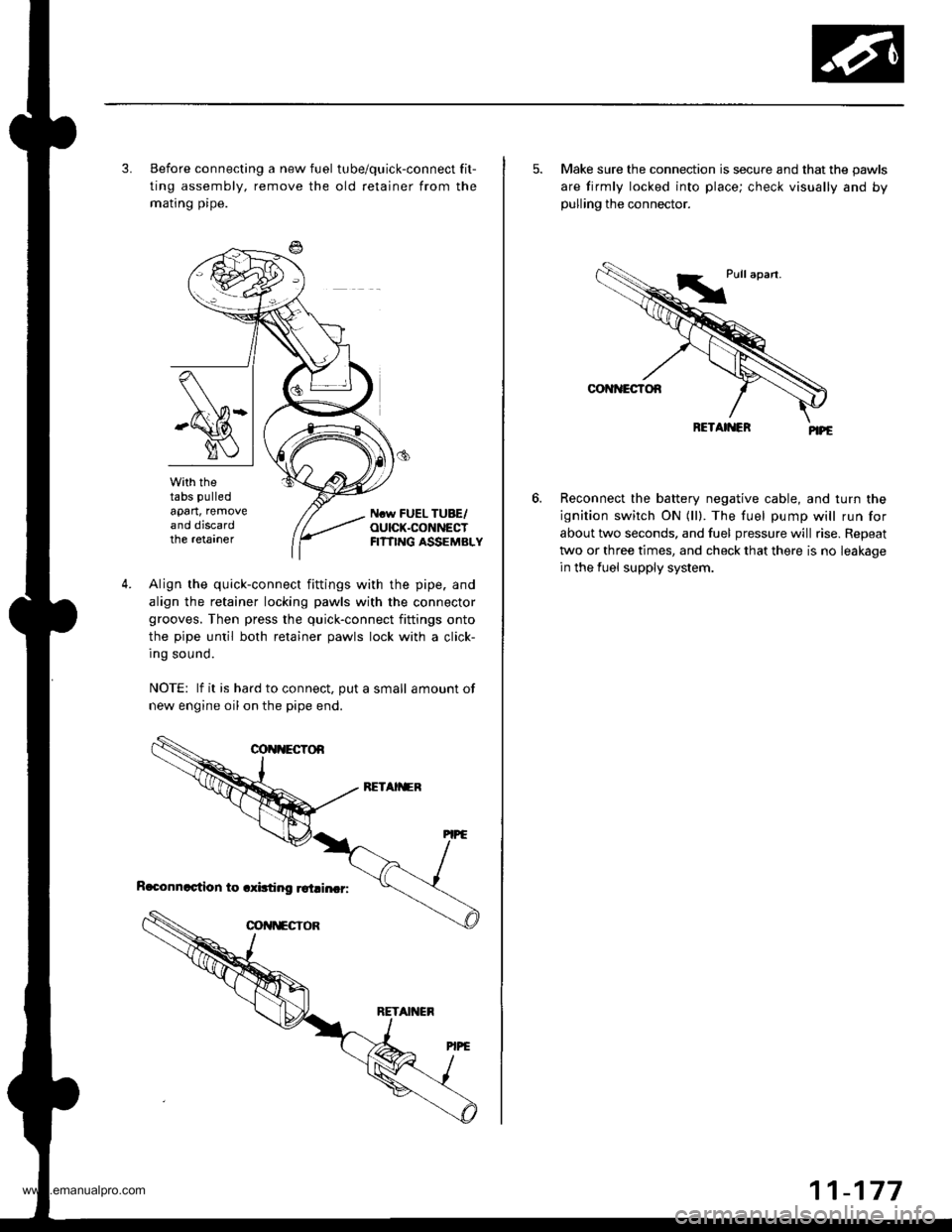
3. Before connecting a new fuel tube/quick-connect fit-
ting assembly, remove the old retainer from the
mating pipe.
with thetabs pulled
apart, removeand discardthe retarner
Ncw FUEL TUBE/OUICK.CONNECTFI?TING ASSEMBLY
4.Align the quick-connect fittings with the pipe. and
align the retainer locking pawls with the connector
grooves. Then press the quick-connect fittings onto
the pipe until both retainer pawls lock with a click-
Ing sound.
NOTE: lf it is hard to connect, put a small amount of
new engine oil on the pipe end.
5. Make sure the connection is secure and that the pawls
are firmly locked into place; check visually and bypulling the connector.
Reconnect the battery negative cable, and turn the
ignition switch ON (ll). The fuel pump will run for
about two seconds, and fuel pressure will rise. Repeat
two or three times, and check that there is no leakage
in the fuel supply system.
6.
www.emanualpro.com
Page 403 of 1395
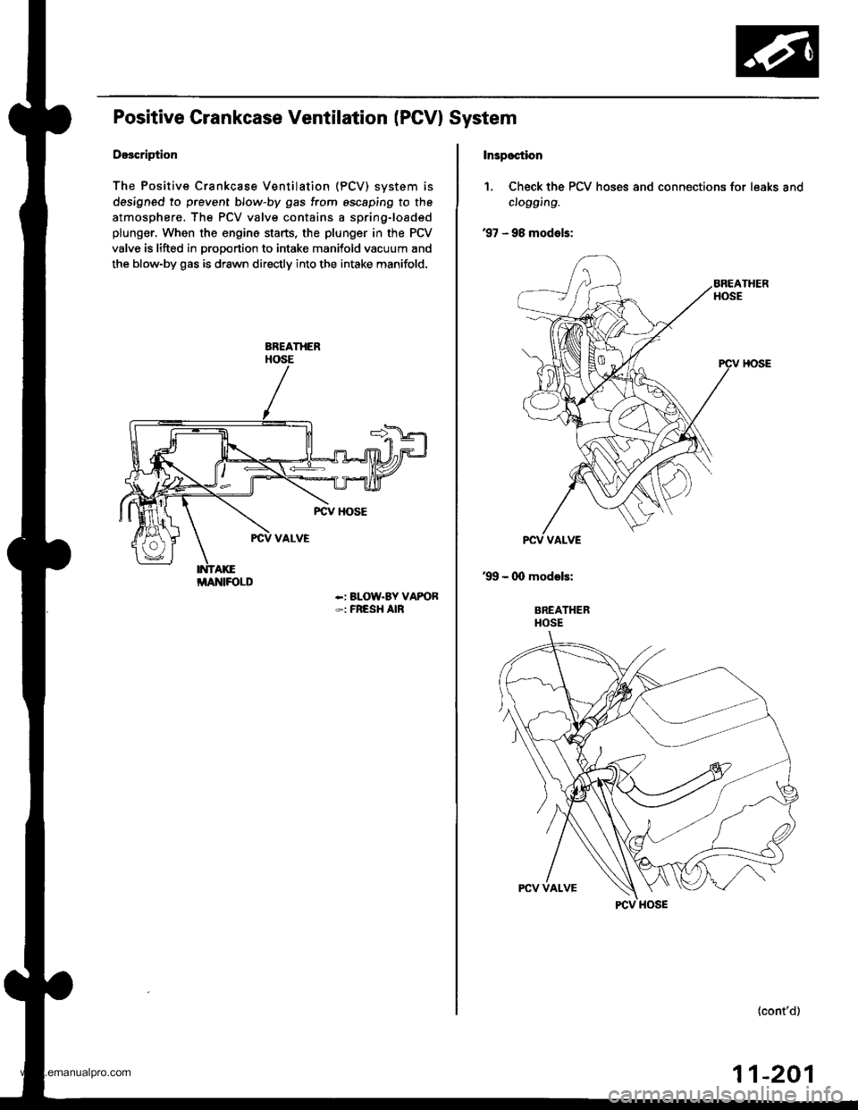
Positive Grankcase Ventilation (PGVI System
Description
The Positive Crankcase Ventilation (PCV) svstem is
designed to prevent blow-by gas from escaping to the
atmosphere. The PCV valve contains a spring-loaded
plunger, When the engine starts, the plunger in the PCV
valve is lifted in proportion to intake manitold vacuum and
the blow-by gas is drawn directly into the intake manifold.
-: BLOW.BY VAPOR-: FRESH AIR
i/lAlrllFOLD
Inspoction
1. Check the PCV hoses and connections for leaks and
clogging.
'97 - 98 models:
'99 - (X) models:
BREATHERHOSE
(cont'd)
11-201
www.emanualpro.com
Page 419 of 1395

EVAP control canister vent shut
valve l€st,lThe conlinualion ot DTC P1456
troubleshooting.)
Check the EVAP control cankter
vent 3hut valve:1. Disconnect the vacuum hose
from the EVAPthree way valve,
and connect a vacuum PUmPto the hose.2. Turn the ignition switch ON (ll).
3. Apply vacuum to the hose
EVAP control crnisier vent lhul
valve is OK. Do the v.cuum
hoses and connections te3l lseepage 11-218).
Does the valve hold vacuum?
Chock the EVAP control canbtel
vent shul valvo:1. Turn the ignition sw;tch OFF.
2. Disconnect the EVAP controlcanister vent shut valve 2P
connector.3. Check for continuity betlveen
the EVAP control canister vent
shut valve 2P connector termi-nal No. 1 snd body ground.
Roplac€ the EVAP contlol canbt€]venl shut valve and O-ring.
Chock lor a short in the wire(VSV lino)r1. Disco n nect the EcM/PCN4connoctor A (32P).
2. Check for continuity betweenthe EVAP control canister vent
shut valve 2P connector termi-
nal No. 1 and body ground.
Reorir 3hort in tho wiro bgtweonthe EC1I/I/PCM lAal .nd the EVAP
codrol canbtor vent shut valv6.
Substitute a known.good ECM/
PCM and recheck. lf symptom/indicrtion goes awaY, replace
the original ECM/PCM.
VACUUMPUMP/GAUGE,0 - 30 in.Hg
A973X - 041 -
XXXXX
EVAPTHREE
VALVEEVAPCONTROLCANISTER
EVAP CONTROLCANISTER VENT SHUTVALVE 2P CONNECTOR IC361)
r+l1t2l
f1 VSV
(o) tLT cnrulwxrt
1
Wire side of female terminals
EVAPCONTROLCANISTERVENTSHUTVALVE
O.RINGReplace.
ILT GRN/WHT)
(cont'd)
-21711
www.emanualpro.com
Page 420 of 1395

Emission Control System
Evaporative Emission IEVAPI Controls (cont'd)
lTi,t56l ("onto)
Vacuum hoses and connectionstelit.(The continuarion of DTC P1456troubleshooiing.l
Check the vacuum ho3es andconnect|ons:Check the following parts forleaks at atmospheric p ressu re{see page 11-204).. Fueltank. Fuel fill cap. Fuelfill pipe. EVAP two way valve. Fueltank pressure sensor
Repair or replaco the parts.
Substitute a known-good ECM/PCM and recheck. lf symptom/indication goes away, replac€the original ECM/PCM.
11-218
www.emanualpro.com
Page 517 of 1395

Automatic Transmission
Special Tools . 14'2OescriptionGeneral Operation . .... 14 3Power Flow . . .. '14_6
Electronic Control System .. .. . . .. .14_15Hydraulic Control .. 14 24Hydraulic Flow....-....... .. . .... .. .. . 14_29Lock'up Syslem .. .'t4'39Electrical SystemComponenl Locdlrons 14 45
PCM Circuil Dragram (A/T Control Svstem)'97 Model ....................... . . .. - . ... .14-46'98Model ................. . ... .. .. .1450'99 00Models.... . .... . . . 1452
PCM Terminal Voltage/Measuring ConditionsA"/T Control System-'97Model ...... ..14'48A,/T Control System -'98 00 Models . . .. . . 14 54
Troubleshooting Procedures .. ..... ... - 14_56Svmotom to comoonent CharlEiectr,cal Syslem -'97 Model . . 14 60Electrical System -'98 - OO Models . .. . . 14_62Electrical Troubleshooting ('97 Model)Troubleshooting Flowaharts .... ..... . .. . . 14_64
Electrical Troubleshooting ('98 - 00 Models)Troubleshootinq Flowclt"n" .... . ....- . .14-93ElectricalTroublesliooting('99 00Models)Troubleshootino FlowchartO/D OFF Indicator Light Does Not Come On 14 131
O/D OFF Indicator Liaht On ConstantlY . . . .1!-132O/D OFF Indicator Light Does Not Come OnEven Though O/D Switch ls Pressed . .... - 14_133
Lock up Control Solenoid Valve A,/B AssemblyTest....................-......... . .14-135Replacement . .ll_135Shifr ControlSolenoid Valve Ay'B Assembl,Test .............................. . .. 14-136
Replacement..............- . .14'136Linear Solenoid AssemblYTest.............................................. .. .... . 14_137Replacement .. . 14138Marnshaftlcountershafl Speed SensorsReplacement ...-... 14_138A/T Gear Position SwitchTest ..........................-... . .. 14-139ReplacementA/T Gear Positionlndicator.................. 14-140
Valve Eodynepair ............................... ..... . . .. - . .. ... 14 192
Assembly .................... .. 1{_193
Valve CapsDesciiption....-........................ .. ...... 14194
tnspeition ................... .. 14' 195
N4ain Valve BodyDisassembly/lnspection/Reassemblv - ...... .. 14_196
Secondarv Valve BodYDisassemblv4nspectron/ReassemblY .. . 14 198
Reoulator Valve Bodvbisassembtv,lnspiction/Reassemblv . 14199
Servo EodvDisassembly/lnspection/Reassembly ... ....14'200
Lock'uo Valve BodYDis;ssembly/lnspection/Reassembly .... . 14_201
MainshaftDisassembly/lnspection/Reassembly .. .. .. ..14'202
Inspection ....-.............. ..11_203
Sealing RingsReilaceient ...... ..... . 14'204
CountershaftDisassembly/lnspection/Reassembly .. . . . . . 11-205
Disassembly/Reassemb|y . . ........ ...... . .. 14_206Inspedron ................ . .... . 14 207
One wav ClutchDisassembly/lnspection/ReassemblY ... 11_209
Sub-shaftDisassembly/lnspection/Reassembly ... . .. . 14-210
oisassembly/Re6ssembly . . ... .-...... . . ..14-211
Sub-shaft BearingsReplacement .......14'212
Clutchllfustrated Index .......... . . .14-213
Disassembly .... .. .....14-216Reassembfy .... . .. .. . 14'218
Differentialllfustrated Index " 14-222Backlash Inspection . .... . .14'223
Bearing Repiacement .. 11-223
Differe-ntial Carrier Replacement .. .. . . . .. ..11-2?4
OifSeal Replacement. . .. 14'225
Side Clearance lnspection . . - .. ... . - ...... . .. 11'226
Transmission Housing BearingsMainshaJVCountershaft EearingsRepfacement .......14221Sub'siralt Eearing Replacement . . . . . . . . . ..11'224
Toroue Converter Housing BearingsMainshattEearing/OilSe6lReplacement . .. l4229
Countershaft Bea;ing Replacement.. .... .. ..14-230
Input Test - '97 - 98 ModelsInput Test '99 - 00 Models
Symptom to-Component ChartHydraulic System ...............
Checking
Removal ...,lllustrated Index (4WD)
Interlock SystemInterlock ControlUnit lnputTest. -..... -.. .... . - 14 144* Key Interlock Solenoid Test .- .. . . . - . . . ..... 14_146* Shift Lock Solenoid Test ..............-.-. . .. . ... .... 14 147*Shift LockSolenoidReplacement...... .. . .. .. 14 148* park pin Switch Test ......... 14 119' Park Pin Switch Replacement- '97 - 98 Models ....... 14-150* Park Pin Swirch/Over Drive (O/Di SwitchReplacemenl '99-00Models . .. 14_151over-Drive (O/D) Switch {'99 00 [4odels]Test........_..................... .......14-152Hydr.ulic System
..............._............... t4 142.................................. 14-143
Control Lever AssemblyR6placement ......,.,Reverse ldler Gear
lllustrated lndex
.......... 14-230
14 231
11-231
1nsta1|ation ..................Park StopInspeclion/AdjustmenlTransfer AssemblY.......14.232
RoadTest.............-.... ........ .StallSpeedTest ....._........................ ....... 14-159Fluid Level......_................... 14'160
Disessembly .................... 14-235Transfer Drive Gear BearingReplacementTrans{er Driven Gesf Shaft BearingReplacementTransfer Housing Roller BearingReplacementTransfer Cov€r A Bearing Outer RaceReplacementTransfer Housing Bearing Outer RaceReplacement ......-..,,,,,.....ReassemblvTransmassaonBeassembly ... -.. .... .14 250
Torque Converier/Drive Plate . .-. .... .. . ... .....14_258
Transmissionlnstatlation .................. ....... 14'259
Cooler Flushing . . ......11-261ATF Cooler HosesConnection.................. ....... 14-266I Shift LeverRemoval/lnstallation . .. 14'261
Disassemblv/Reassemblv - '97 - 98 Models . . 14_264
Disassembli/Reassemblv -'99 - 00 Models . 14-269
Over'Orive (O/D) Switch WireClearanceAdjustment. - ... . . . .. .. . 14'270
Detent Spring Replscement . . -.. ... .14'271*Shift CableAdiustment ....... 14'272
Repfacement.............. . 11'273
14 15711-237
11-237
14-238
$-234
11-23914-240
Transmigrion
Inspeclron ....., ...........Transfer AssemblyRemova1,.,,,..............,lnstallalion ........... .. ...Transmission
14 164
14-16514,167
14-169
End Cover/Transmissio . 14'174Transmission Housing .... ... .. . . .... .. 14-176Torque Converter Housingly'alve Body.. - ... -. 14 178
lllustrated lndex (2WD)End Cover/Transmissio ....... 14 180Transmission Housing . . ... . .. .... ... 14'182Torque Convener Housing/r'alve Body ......- 14-184
End CovefRemovat ...................... ....... 14'186Transmission HousingRemoval ...................... .. 14_188Torque Convener HousingA/alve BodYRemovat ................-..... .-..... 14-190
www.emanualpro.com