Page 1131 of 1395
Mode Control Motor
Replacement
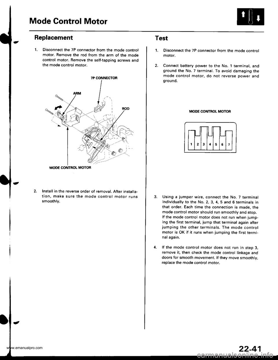
1. Disconnect the 7P connector from the mode control
motor. Remove the rod from the arm of the mode
control motor, Remove the self-tapping screws and
the mode control motor.
2.Install in the reveGe order of removal. After installa-
tion, make sure the mode control motor runssmoothlv.
7P CONNECTOR
MODE CONTROL MOTOR
Test
1.Disconnect the 7P connector from the mode control
motor.
Connect battery power to the No. 1 terminal, andground the No. 7 terminal. To avoid damaging the
mode control motor, do not reverse power andgrouno.
MODE CONTROL MOTOR
Using a jumper wire. connect the No. 7 terminalindividually to the No, 2,3, 4,5 and 6 terminals in
that order. Each time the connection is made. the
mode control motor should run smoothly and stop.
lf the mode control motor does not run when jump-
ing the first terminal, jump that terminal again afterjumping the other terminals. The mode control
motor is OK it it runs when jumping the first termi-
nal again.
lf the mode control motor does not run in step 3,remove it, then check the mode control linkage and
doors for smooth movement. lf they move smoothly,
reDlace the mode control motor.
www.emanualpro.com
Page 1133 of 1395
Air Mix Gontrol Motor
Replacement
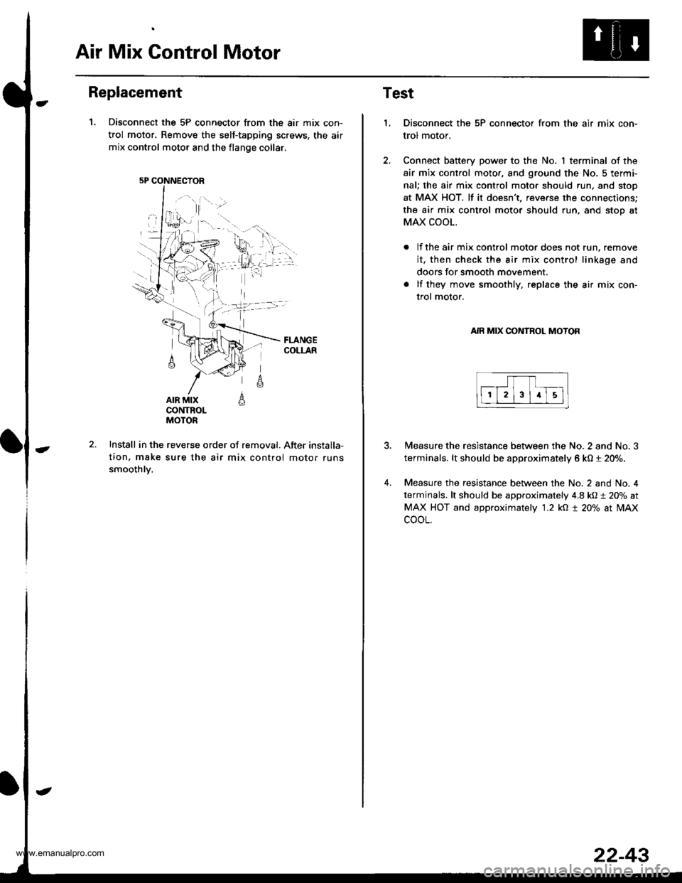
1. Disconnect the 5P connector from the air mix con-
trol motor. Remove the self-tapping screws, the air
mix control motor and the flange collar.
AIR MIXCONTROLMOTOR
A
6
Install in the reverse order of removal. After installa-
tion. make sure the air mix control motor runs
smoothlv.
5P CONNECTOR
22-43
Test
1.Disconnect the 5P connector from the air mix con-
trol motor.
Connect battery power to the No. I terminal of the
air mix control moto., and ground the No, 5 termi-
nal; the air mix control moto. should run, and stop
at MAX HOT. lf it doesn't, reverse the connections;
the air mix control motor should run, and stoo at
MAX COOL.
lf the air mix control motor does not run, remove
it, then check the air mix control linkage and
doors for smooth movement.
lf they move smoothly, replace the air mix con-
trol motor.
AIR MIX CONTROL MOTOR
4.
Measure the resistance between the No. 2 and No. 3
terminals. lt should be approximately 6 kO t 20%.
Measure the resistance between the No. 2 and No, 4
terminals, lt should be approximately 4.8 kO:t 20% at
MAX HOT and approximately '1.2 kO t 20% at lilAx
cooL.
www.emanualpro.com
Page 1163 of 1395
Troubleshooting
Tips and Precautions
Bef ore Troubleshootin g
. Check applicable fuses in the appropriate fuse/relay
box.
. Check the battery for damage, state of charge, and
clean. and tight connections.
. Check the alternator belt tension.
CAUTION:
. Do not quick-charge a battery unless the battery
ground cable has been disconnected, otherwise you
will damage the alternator diodes.
. Do not attempt to crank thc engins wilh the battery
ground cable loosely connected or you will severely
damage the wiring.
Handling Connestors
. Make sure the connectors are clean and have no loose
wire terminals,
. N4ake sure multiple cavity connectors are packed with
grease (except water-tight connectors).
. All connectors have push-down release type locks.
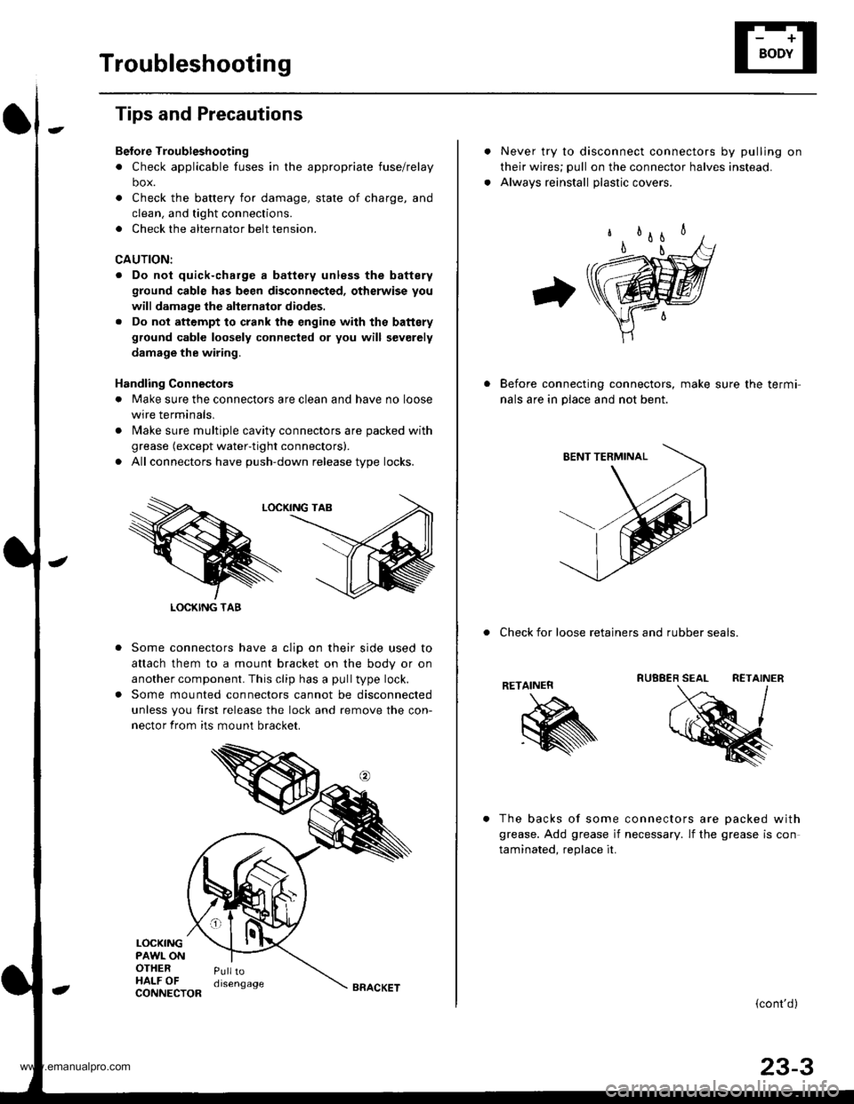
Some connectors have a clip on their side used to
attach them to a mount bracket on the body or on
another component. This clip has a pull type lock.
Some mounted connectors cannot be disconnected
unless you first release the lock and remove the con-
nector from its mount bracket.
LOCKINGPAWL ONOTHERHALF OFPulltodisengage
LOCKING TAB
CONNECTORBRACKET
Never try to disconnect connectors by pulling on
their wires; pull on the connector halves instead.
Alwavs reinstall olastic covers.
Before connecting connectors, make sure the termi-
nals are in place and not bent.
. Check for loose retainers and rubber seals.
RETAINER
The backs of some connectors are oacked with
grease. Add grease if necessary. lf the grease is con
taminated. reolace it.
{cont'd}
23-3
www.emanualpro.com
Page 1310 of 1395
)
Supplemental Restraint System (SRS)
Special Tools .."....."" 24-14
Component/Wring Location
lndex - '97 model ..........'.." '.....""" 24-15
Component/Wiring Location
lndex - '98 - 00 models ..............." 24-16
Description .'.........."'.24'17
Circuit Diagram .........24'14
Precautions/Procedures
General Precautions ......".."'........... 24-19
Airbag/Seat Belt Tensioner
Handling and Stolage ....''........... 24-19
SRS Unit Precautions ...............'...... 24-20
lnspeciion After Deployment .......'.24'20
)
SpringJoaded Lock Connector
with Built-in Short Contact '...'....24-21
Spring-loaded Lock Connectors .."' 24-22
BackProbing SPring-loaded Lock
Conneetors ,.......24-22
Disconnecting the Airbag Connectors and
the Seat Beh Tensioner
Connectors ....'....24-23
Steering-lelated Precautions .......... 24-25
Troubleshooting
Self -diagnostic Procedures ............. 24-26
Reading the DTC .................. .....".."' 24'26
Erasing the DTC Memory ................24-28
Troubleshooting lntermittent
Faifures "'...........24'24
Diagnostic Trouble Gode {DTC}
Chart -'97 model ....""....... "......24-29
Diagnostic Trouble Gode (DTCI
Chart -'98 - 00 models ............. 24-31
SRS Indicator Light Wire
Connections ','," 24'33
Ff owcharts ....-........24'34
Driver's Airbag
Repf acement ..'......21'87
Front Passenger's Airbag
Repfacement .....'.',24'AS
Gable Reel
Replacement .......'.24-91
SRS Unit
Replacement .........24-95
Airbag/Seat Belt Tensioner
Disposaf .................24'97
)-e
www.emanualpro.com
Page 1330 of 1395
SRS Indicator Light Wire Connections
SRS Indicator Light Power Circuit
DASHBOARD WIRE HARNESS
YEL
BLK
To UNDER-DASHFUSE/RELAY BOX <_
20P CONNECTOR
To GAUGEcsog + assEMBLy
SRS Indicator Light Control Circuit
SRS MAIN HARNESS
)-MAIN WIRE HARNESS
VAIVBIt
To UNDER-DASHFUSE/BELAY BOX2P CONNECTOR
c414MAIN WIRE HARNESS 3P CONNECTORTerminal side of msle t€rminals
c415MAIN wlRE HARNESS 24P CONNECTORTerminal aide of male terminals
c502DASHBOARD WIRE HARNESS 2OP CONNECTORWire side of lemslo terminsls
c503OASHBOARD WIRE HARNESS 24P CONNECTORWire side of female t€rminal3
c509DASHBOABD WIRE HARNESS 5P CONNECTORWire sid€ ot lemale te.minals
c801SRS MAIN HARNESS 2P CONNECTORwire side ol f.male terminals
c803SRS MAIN HARNESS 3P CONNECTORWire side ol female terminals
c806SRS MAIN HARNESS T8P CONNECTORWire side of lomrle terminals
)
24-33
www.emanualpro.com
Page 1364 of 1395
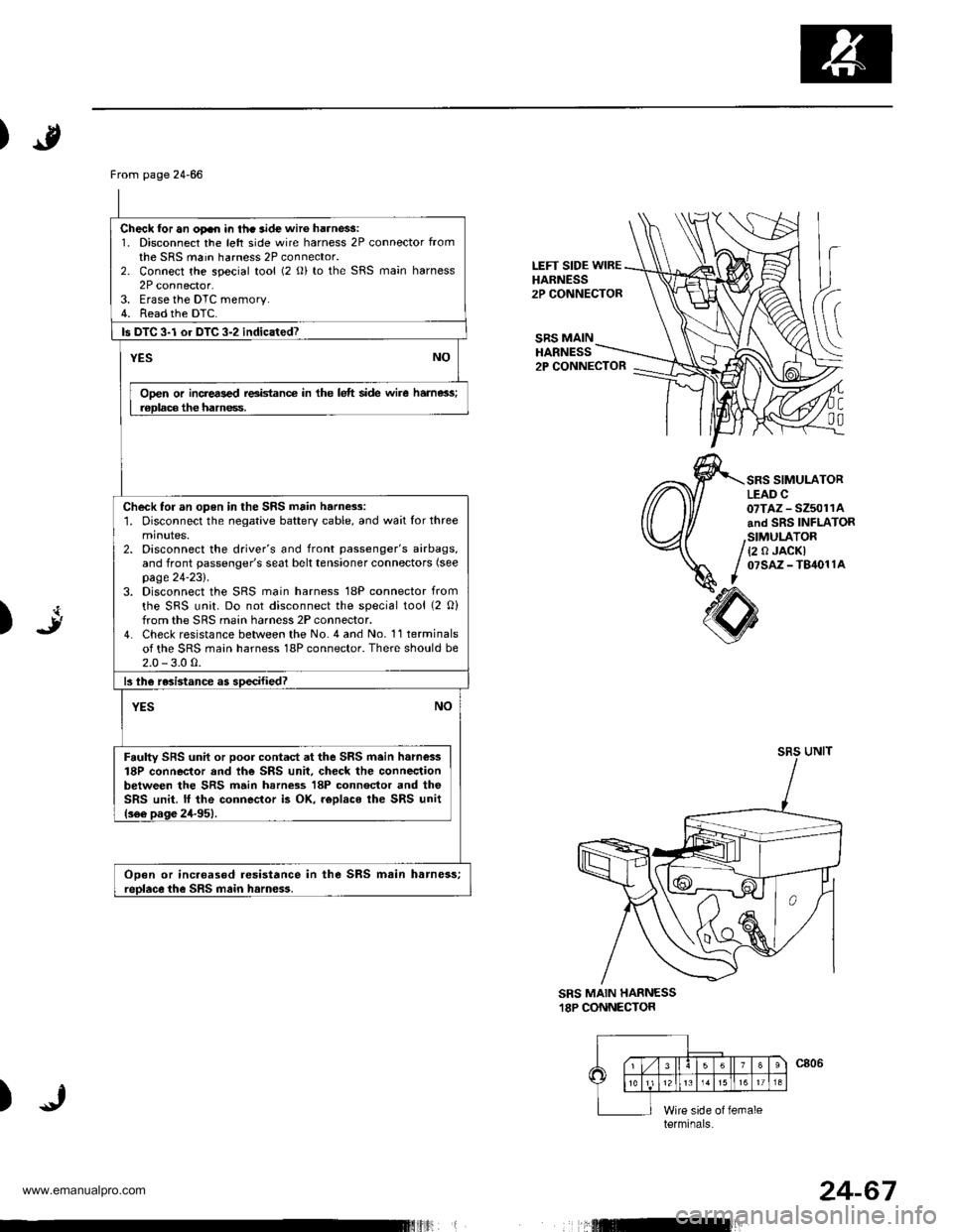
)
LEFT SIDE WIREHARNESS2P CONNECTOR
SRS MAINHARNESS2P CONNECTOR
C
00
SRS SIMULATORLEAD C07TAZ - SZ5011Aand SRS INFLATOR
{2 0 JACKI07sAz - T84011A
art)
sRsUNIT
SRS MAIN HARNESS.I8P CONNECTOR
)
From page 24-66
Check for an oFn in thc aide wir6 harne$:1. Disconnect the left side wire harness 2P connector fromthe SRS main harness 2P connector.2. Connect the special tool (2 o) to the SRS main harness2P connector.3. Erase the DTC memory.4. Read the DTC.
ls DTC 3-l or DTC 3-2 indicated?
YESNO
Ooen or incrers€d reeidance in the lelt side wire hame3s;r€Dlaca the hamess.
Check for an open in the SRS main harness:1. Disconnect the negative battery cable, and wait for threeminutes.2. Disconnect the driver's and front passenger's airbags,and front passenger's seat belt tensioner connectors (see
page 24-231.3. Disconnect the SRS main harness 18P connector from
the SRS unit. Do not disconnect the special tool (2 O)from the SRS main harness 2P connector.4. Check resistance between the No. 4 and No. 11 terminalsof the SRS main harness 18P connector. There should be2.0 - 3.0 0.
13lhe resistance as soecified?
NOYES
Faulty SFS unil or poor contad at the SRS main h.m€ss18P connector and th€ SRS unit. check the connectionbetween the SRS main harn$s 18P connector and theSRS unit. lf the connector i3 OK. r€Dlaco ihe SRS unit(s66 pas6 24-951.
ODen or incaoased resistance in the SRS msin harness;reolace the SRS main harn€ss.
terminals
24-67
www.emanualpro.com