Page 229 of 1395
System Description
Electrical Connections - '98 - 00 Models (cont'dl
!to2srficSECOiD hYHO2a (aE toh 2)
11-26
G]-l
ct sEt{goh
' c14t
I J/C
llo23 (SEltgOi O
l-
www.emanualpro.com
Page 231 of 1395
System Description
Electrical Connections -'98 - 00 Models lcont,dl
+lM
- + sL( yEL JJ{FiE-l
l-- sLU wnf - li,"+l_ 8rk _{lr]]]]]]] |
i
w;i-nu -
--- t_.1rq-vJK
CONOEflSER FANRELAY
rlrA/T.2: USA*4: '99 - 00 models
F >rt
-4.
" l---r'a
11-28
www.emanualpro.com
Page 235 of 1395
System Description
Electrical Connections -'98 - 00 Models (cont,dl
OVE&ORVE OFF[{DtcatoR LlfP
C UqE AASEr|ELY
A/I GEAA PO3MON SWITCH
*tnzaeo' ) ,r*ear_oo,
11-32
@lillFo|. ur{tT
*1: Nf*4: '99 - 00 modets
www.emanualpro.com
Page 237 of 1395
System Description
Electrical Connections -'98 - 00 Models (cont'dl
PGU.FIMAII{ BEIAY
cssr
cs6-2 ,z-_\-YEL/GBN-
-f p \-BLx-- l ./| - "---.,
_L FUEL PUI{P
11-34
www.emanualpro.com
Page 280 of 1395

Troubleshooting
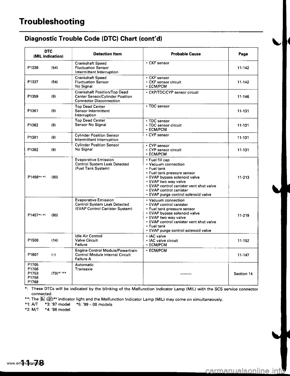
Diagnostic Trouble Code (DTCI Ghart (cont'd)
r: These DTCS will be indicated by the blinking oJ the Malfunction Indicator Lamp (MlL) with the SCS service connectorconnected.**: The Di (E)*5 indicator light and the Malfunction tndicator Lamp (MlL) may come on simultaneously.*1: A[f *3;'97 model *5: '99 - 00 models*21M/f *4: '98 model
11-78
DTC
{MlL indication}Detection ltemProbable CausePagc
P1336 154)Crankshaft SpeedFluctuation SensorIntermittent Interruption
. CKF sensor
11-142
P1337 i54)Crankshaft SpeedFluctuation SensorNo Signal
CKF sensorCKF sensor circuitECM,FCM11-142
P1359 (8)Crankshaft Position/Too DeadCenter Sensorrcylinder PositionConnector Disconnection
' CKP/TDC/CYP sensor circuit11-146
P1361 (8)Top Dead CenterSensor IntermittentInterruption11-131
P1362 (8)Top Dead CenterSensor No SignalTDC sensorTDC sensor circuitECM/PCM11-131
P1381 (9)Cylinder Position SensorIntermittent Interruption
. CYP sensor11-131
P1382 (9)Cylinder Position SensorNo SignalCYP sensorCYP sensor circuitECM/PCM11-131
P1456n.* {90}
Evaporative EmissionControl System Leak Detected(FuelTank System)
Fuelfill capVacuum connectionFueltankFuel tank prossure sensorEVAP bypass solenoid valveEVAP two way valveEVAP control canister vent shut valveEVAP control canisterEVAP purge controlsolenoid valve
11-213
Pr457n.s {90)
Evaporative EmissionControl System Leak Detected(EVAP Control Canister Svstem)
Vacuum connectionEVAP control canisterFuel tank pressure sensorEVAP bypass solenoid valveEVAP two way valveEVAP control canister vent shut valveFueltankEVAP purge controlsolenoid valve
11-219
P1508 (14)ldle Air ControlValve CircuitFailure
IAC valveIAC valve circuitECM/PCM11-152
Pr607(-)Engine Control Module,PowertrainControl Module Internal CircuitFailure A
. ECM,FCM11-147
P1705P1706P1753P1758P1768
AutomaticTransaxle
Section '14
www.emanualpro.com
Page 281 of 1395

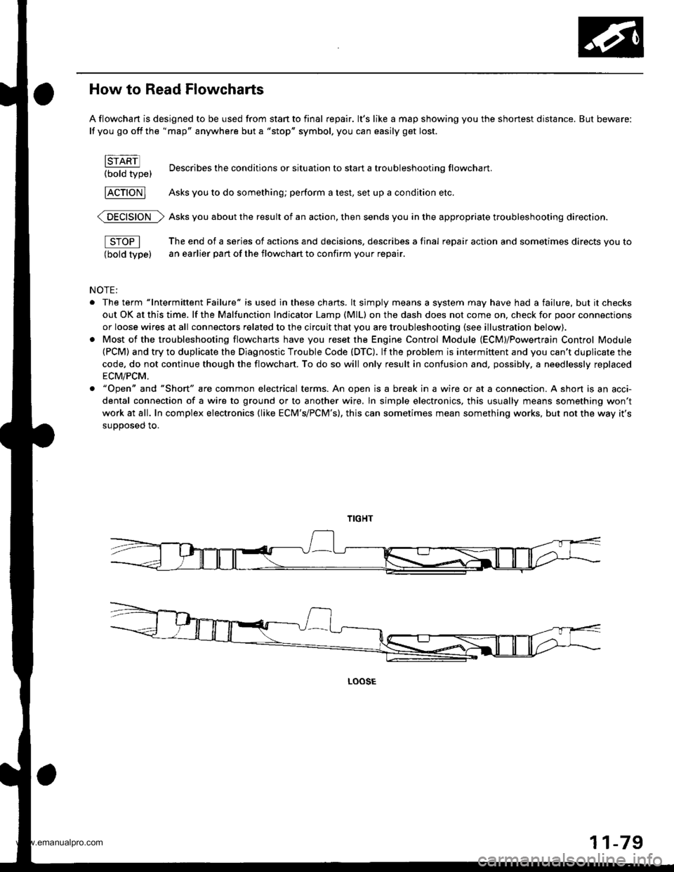
How to Read Flowcharts
A flowchart is designed to be used from start to final repair. lt's like a map showing you the shortest distance. But beware:
lf you go off the "map" anywhere but a "stop" symbol, you can easily get lost.
brARn
t.-OotO tw"t Describes the conditions or situation to start a troubleshooting flowchart.
FcTloNl Asks you to do something; perform a test, set up a condition etc.
@ Asks you about the result of an action, then sends you in the appropriate troubleshooting direction.
fS-OPl The end of a series of actions and decisions, describes a final repair action and sometimes directs you to
(bold type) an earlier part of the flowchart to confirm your repair.
NOTE:
. The term "lntermittent Failure" is used in these charts. lt simply means a system may have had a failure, but it checks
out OK at this time. lf the Malfunction Indicator Lamp (MlL) on the dash does not come on, check for poor connections
or loose wires at all connectors related to the circuit that you are troubleshooting (see illustration below).
. Most of the troubleshooting flowcharts have you reset the Engine Control Module (EcM)/Powertrain Control Module(PCM) and try to duplicate the Diagnostic Trouble Code (DTC). lf the problem is intermittent and you can't duplicate the
code, do not continue though the flowchart. To do so will only result in confusion and, possibly, a needlessly replaced
ECM/PCM,
o "Open" and "Short" are common electrical terms. An open is a break in a wire or at a connection. A short is an acci-
dental connection of a wire to ground or to another wire. ln simple electronics, this usually means something won't
work at all. In complex electronics (like ECM'S/PCM'S), this can sometimes mean something works, but not the way it's
suooosed to.
LOOSE
11-79
www.emanualpro.com
Page 284 of 1395

PGM-FI System
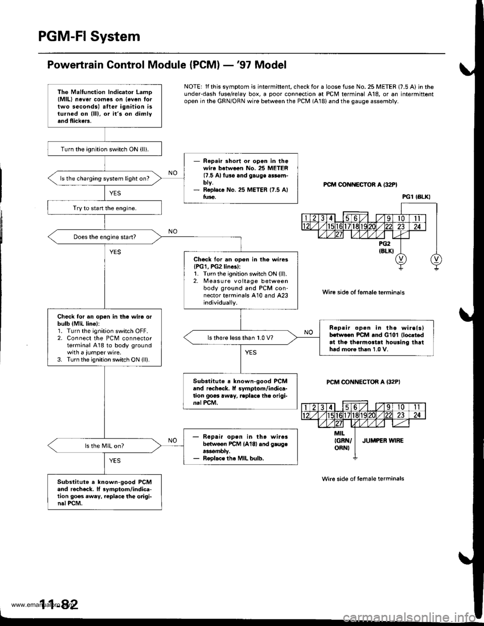
Powertrain Control Module {PCM} -'97 Model
NOTE: lf this symptom is intermiftent, check for a loose fuse No. 25 METER (7.5 A) in theunderdash f{rse/relay box, a poor connection at PCM terminal A18, or an intermittentopen in the GRN/ORN wire between the PCM (A18) and the gauge assembly.
PCM OON ECTOR A {32P}
Wire side of female terminals
PCM CONNECTOR A {32PI
Wire side ot temale terminals
11-42
The Malfunction lndicator LamD(MlL) nev6r comes on {even lortwo seconds) after ignition isturned on (lll, or it's on dimlyand flickers.
Turn the ignition switch ON {ll}.
- Rep.ir short or opon in thowire batween No. 25 METER(7.5 Alfuso and gauge a$€m-bty.- R6pl.c€ No. 25 METER 17.5 Alfus€.
ls the charging system light on?
Try to stan the engine.
Does the engine start?
Chock tor.n open in th6 wire3{PG1, PG2linesl:1. Turn the ignition switch ON (ll).2. Measure voltage betweenbody ground and PCM con-nector terminals A10 and A23individually.
Check for an op€n in the wir6 orbulb (MlL lin€l:1. Turn the ignition switch OFF.2. Connect the PCM connectorterminal A18 to body groundwith a iumper wire.3. Turn the ignition switch ON {ll).
n€peir open in tho wirelslhwoon PCM and Glol (loc!t.d
at thc tha.mo3tat houling thrthtd moro th.n 1.0 V.
ls thore l€ss than 1.0 V?
Substituto . known-good PCMand r€check. ll symptom/indica-tion goss away, rcplaca the origi-nal PCM.
- R6pai. open in th. wileibelwoon rcM lAl8l dnd g.ugea3rombly.- Roolac€ the MIL bulb.
ls the MIL on?
Substitut6 a known-good PCMand rocheck. ll 3ymptom/indica-tion goes away, replace the o.igi-n.l PCM.
PGl IBLKI
www.emanualpro.com
Page 287 of 1395

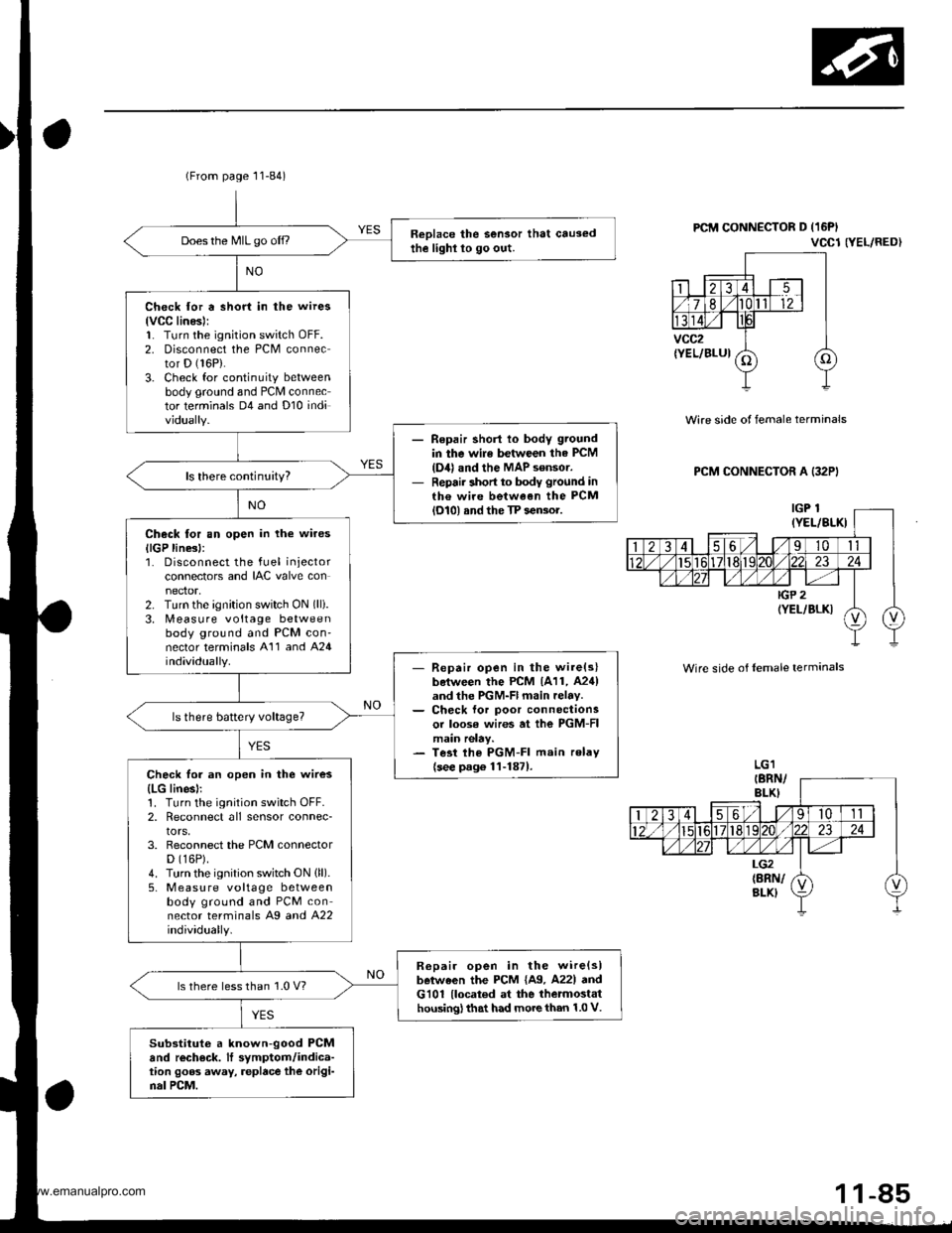
(From page 11-84)
Reolace the Sensor that causedthe lighl lo go out.Does the MIL go off.,
Check for a short in the wires
lvCC linesl:1. Turn the ignition switch oFF.2. Disconnect the PCM connector D (16P).
3. Check for continuity betweenbody ground and PCM connector terminals D4 and Dl0 individually.
Repair shorl lo body ground
in the wile between the PCM
{D4} and the MAP sensor.Repair short to body ground inth€ wire between the PCMlol0l and the TP sensor.
Check tor an open in the wires
llGP line3l:1. Disconnect the fuel injectorconnectors and IAC valve con
2. Turn the ignition switch ON (lli.
3. [,4easure voltage betweenbody ground and PCM con'nector terminals A'11 and A24individually.- Repair open in the wire(slboiween the PCM 1A11, A24)and the PGM-Fl main relav.- Ch€ck lor poor connectionsor loose wires at ihe PGM-FImain relay.- Tesi lhe PGM-FI main relav
{see p.g6 1l-1871.Check for an open in the wires
{LG linesl:1. Turn the ignition switch OFF.2, Reconnect all sensor connec-tors,3. Reconnect the PCM connectorD (16P).
4. Turn the ignition switch ON (ll).
5, M easu re voltage betweenbody ground and PCM connector terminals Ag a^d 422individually.
R6pair open in the wire{slbetween the PCM {A9. A22l andG101 {located at the thetmostathousing) that had more than 1.0 V.
ls there less than 1.0 V?
Substituto a known-good PCMand rech€ck. It symptom/indica-tion goos away, replace the origi-nal PCM.
PCM CONNECTOR D (16PI
VCCl NEL/RED}
Wire side of female terminals
PCM CONNECTOR A (32PI
Wire side of lemale terminals
1 1-85
www.emanualpro.com