2000 HONDA CR-V Start
[x] Cancel search: StartPage 520 of 1395

Description
General Operation (cont'dl
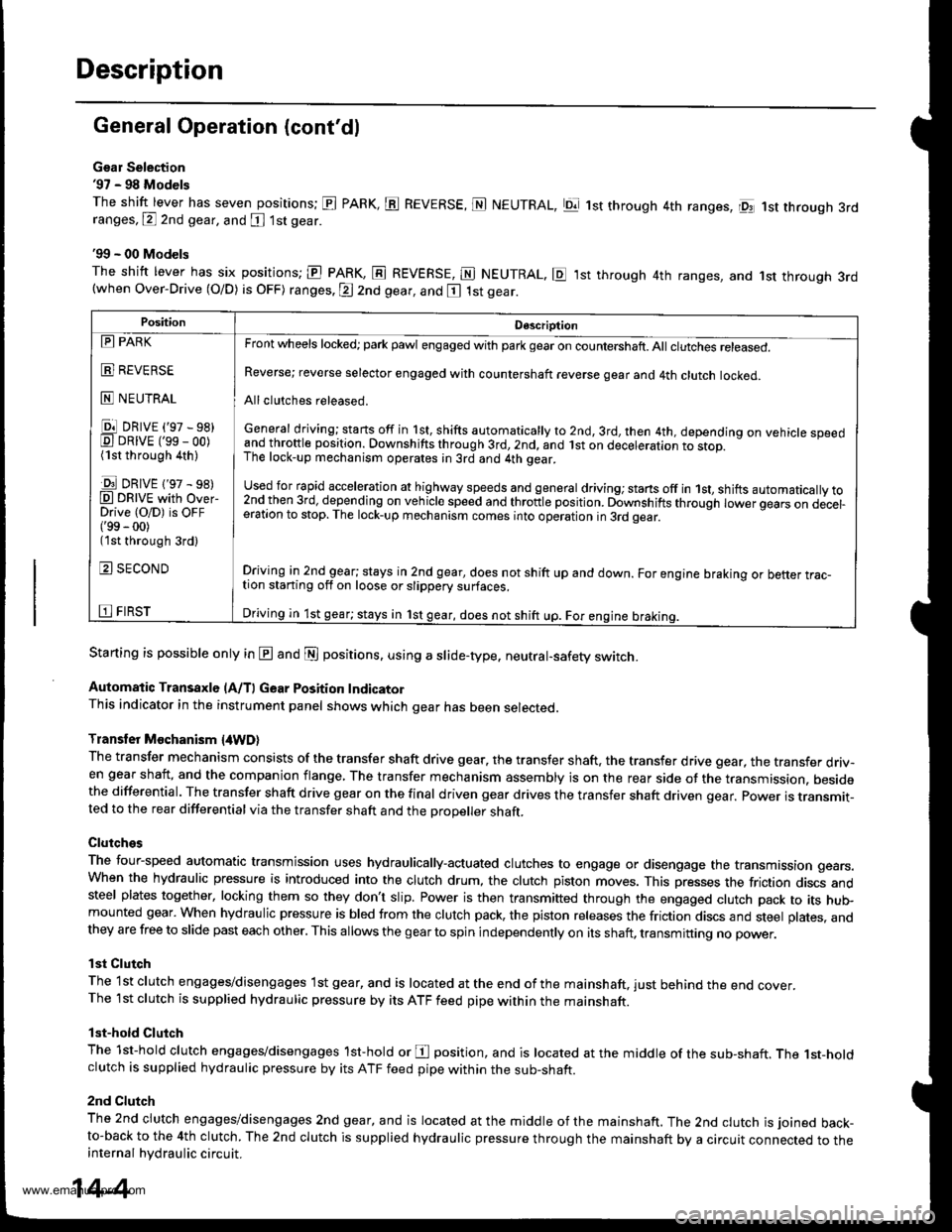
Gsar Selection'97 - 98 Models
The shift lever has seven positions; El PARK, ts REVERSE, N NEUTRAL, Ell 1st through 4th ranges, lpq 1st th.ough 3rdranges, P 2nd gear, and [ 1st gear
'99 - 00 Models
The shitt lever has six positions; El PARK, E REVERSE, E NEUTRAL. E ,lst through 4th ranges, and 1st through 3rd(when Over-Drive (O/D) is OFF) ranges. @ 2nd gear, and E 1st gear.
Starting is possible only in @ and @ positions. using a slide-type. neutral-safety switch.
Automatic Transaxle (A/T) Gear Position IndicatorThis indicator in the instrument panel shows which gear has been selected.
Transler Mochanism {4WD}
The transfer mechanism consists of the transfer shaft drive gear. the transfer shaft. the transfer drive gear, the transfer driv-en gear shaft, and the companion flange, The transfer mechanism assembly is on the rear side ot the transmission. besidethe differential. The transfer shaft drive gear on the final driven gear drives the transfer shaft driven qear. power is transmit-ted to the rear differential via the transfer shaft and the Drooeller shaft.
Clutches
The four-speed automatic transmission uses hydraulically-actuated clutches to engage or disengage the transmission gears.When the hydraulic pressure is introduced into the clutch drum, the clutch piston moves. This presses the friction discs andsteel plates together, locking them so they don't slip. Power is then transmifted through the engaged clutch pack to its hu$mounted gear. When hydraulic pressure is bled from the clutch pack, the piston releases the friction discs and steel plates, andthey are free to slide past each other. This allows the gearto spin independently on its shaft, transmitting no power.
lst Clutch
The 1st clutch engages/disengages lst gear, and is located at the end ofthe mainshaft, just behind the end cover.The 1st clutch is supplied hydraulic pressure by its ATF feed pipe within the mainshaft.
lst-hold Clutch
The 1st-hold clutch engages/disengages 1st-hold or E position, and is located at the middle of the sub-shaft. The 1st-holdclutch is supplied hydraulic pressure by its ATF feed pipe within the sub-shaft.
2nd Clutch
The znd ciutch engages/disengages 2nd gear, and is located at the middle of the mainshaft. The 2nd clutch is joined back-to-back to the 4th clutch. The 2nd clutch is supplied hydraulic pressure through the mainshaft by a circuit connected to theinternal hydraulic circuit.
PositionDescription
Reverse; reverse selector engaged with countershaft reverse gear and 4th clutch locked.
Allclutches released.
General driving; starts off in 1st, shifts automatically to 2nd, 3rd, then 4th, depending on vehicle speedand throftle position. Downshifts through 3rd,2nd, and lst on deceleration to stop.The lock-up mechanism operates;n 3rd and 4th gear.
used for rapid €cceleration at highway speeds and general driving; stans off in 1st, shifts automatically to2nd_then 3rd, dejending on vehicle speed and throttle position. Downshifts through lower gears on decel-eration to stop. The lock-up mechanism comes into operation in 3rd gear.
Driving in 2nd_gear; stays in 2nd gear, does not shift up and down. For engine braking or better trac_tion starting off on loose or slippery surfaces.
Driving in 1st gear; stays in 1st gear, does not shift up. For engine braking.
tll PARK
t!!l l|EvEn>E
E NEUTRAL
Ell DRrvE ('97 - sB)E DRrvE ('ss - oo)(1st through 4th )
E DRrvE {'97 - s8)O DRTVE with over-Drive (O/D) is OFF('99 - 00)(1st through 3rd)
E SECOND
E FIRST
14-4
www.emanualpro.com
Page 546 of 1395

Description
Hydraulic Flow (cont'dl
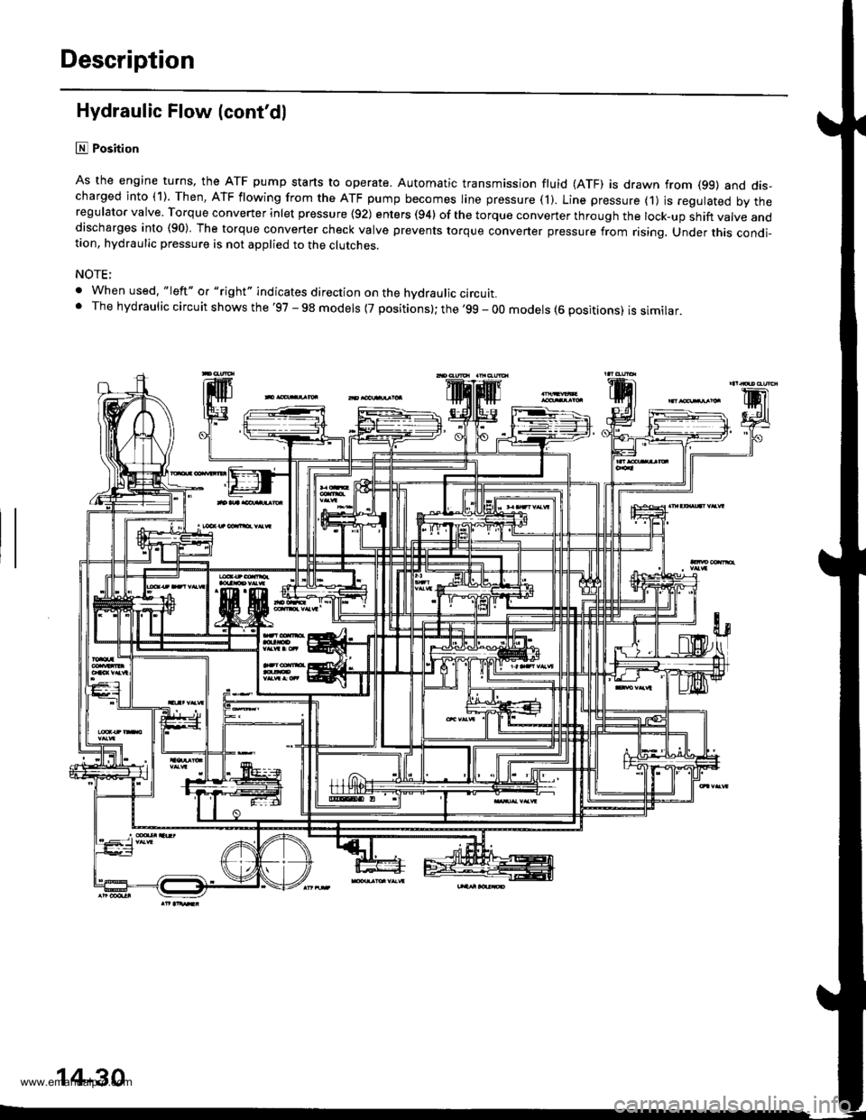
lll Position
As the engine turns, the ATF pump starts to operate. Automatic transmission fluid (ATF) is drawn from (99) and dis-charged into (1). Then, ATF flowing from the ATF pump becomes line pressure ('l). Line pressure (1) js regulated by theregulator valve. Torque converter inlet pressure {92) enters (94) of the torque conveTter through the lock-up shift valve anddischarges into (90) The torque converter check valve prevents torque converter pressure from rising. Under this condi-tion, hydraulic pressure is not applied to the clutches.
NOTE;
. When used. "|eft" o. "right" indicates direction on the hvdraulic circutt.. The hydraulic circuit shows the '97 - 98 models {7 positions}; the '99 - 00 models (6 positions) is similar.
'lF'.j.l
14-30
www.emanualpro.com
Page 657 of 1395
![HONDA CR-V 2000 RD1-RD3 / 1.G Workshop Manual
8. Set the control shaft to E] position. then install the
A,/T gear position switch on it.
CONTROL SHAFT
Install the AyT gear position switch cover and har-
ness clamp on the end cover.
Connect the HONDA CR-V 2000 RD1-RD3 / 1.G Workshop Manual
8. Set the control shaft to E] position. then install the
A,/T gear position switch on it.
CONTROL SHAFT
Install the AyT gear position switch cover and har-
ness clamp on the end cover.
Connect the](/manual-img/13/5778/w960_5778-656.png)
8. Set the control shaft to E] position. then install the
A,/T gear position switch on it.
CONTROL SHAFT
Install the Ay'T gear position switch cover and har-
ness clamp on the end cover.
Connect the A,/T gear position switch connector.
then install it on the connector bracket.
Turn the ignition switch ON (ll). Move the shift lever
through all gears, and check the AfI gesr position
switch synchronization with the A/T gear position
indicator.
9.
10.
11.
A/TGEARPOSMON A/T GEAR POSITIONINDICATOR INDICATOR'99 - 00 MODELS '�97 - 98 MOOELS
12, Start the engine. Move the shift lever through all
gears. and verify the following:
. The shift lever cannot be moved to E] position
from E position unless the shift lever is pulled.
. The engine will not start in any position other
than E or E.. The back-up lights come on when the shift lever
is in El position.
14-141
www.emanualpro.com
Page 669 of 1395

Symptom-to-Component Chart
Hydraulic System
Before troubleshooting a problem on Hydraulic system, check the self-diagnosis Dl ('97 - 98) or Lq ('99 - 00) indicator
light indication. lf the El or E indicator light indicates a trouble code, perform the electrical troubleshooting according to
the Electrical System-to-Component Chart. lf the Ol or E indicator light does not indicate a trouble code and failure is not
found on the electrical troubleshooting, perform the hydraulic troubleshooting following the chart.
SYMPTOMCheck these items on the
PROBABLE CAUSE List
Check these items on
the NOTES List
Engine runs, but vehicle does not move in any gear.1r2FAt?82?K,L.R,S
Vehicle moves in El. @, but not in lE. E, E, or E, position6, 8, 9, 10, 29, 52c,M,o
Vehicle moves in [D!. E, E. E, E, but not in E] position.al
Vehicle moves in .&1, E. E, E, E, but not in E position4,6, 14, 15c,L.o
Vehicle moves in E position.10 , 12, 13, '�l4, '16, 2A, 32, 33, 34
Excessive idle vibration1,2, 18,3'1,35, 44, 46, 41B,K,L
Poor acceleration; flares on starting off in E, Di position
or E position
Stall rpm hish in El, El, E, E, E Position
Stall rpm hiqh in E, E, E, E position
1,2,3,6,37, 40K,L,R
6, 8, 10C,D
Stall rpm high in E positionc,D
Stall rpm high in hl position14N
Stall rpm low17,31, 44, 46, 47R
No shift18, 19, 39, 47, 48G,L
Fails to shift in Pr, E position or E position; from 1st to
3rd gear
21, 48
Fails to shift in EJ, E position or E position; from 1st to
4th gear
21,22, 47
Erratic upshifting
fz upshlft. ,3 ripshlft, 3r. up+ilft57
ffi20, 47
il21, 4A
3-4 upshift22, 47
Harsh upshift ('l-2)12, 18, 19,2A,49, 50, 56, 57
Harsh upshift (2-3)13, 1A, 19,23,26,28, 49, 50, 56, 57C,D.E,H,L
Harsh upshift {3-4)14,1A, 19,24,27,28, 49, 50, 56. 57C, D, E, I,L
Harsh downshitt (2-1)18, 19,23, 42,53,56,51o
Harsh downshift (3-2)12, 18,19,24,41,42, 54. 56, 57, 58
Harsh downshift (4-3)13,'1A, 19, 25, 41, 42, 55, 56, 57C, D, E, I
Flares on 2-3 upshift13,1A,19,23,26,50FI
Flares on 3-4 upshift14, 1A, 19,24,27,50E,L,N
Excessive shock on 2-3 upshift13. '18, 19 , 23, 26, 42, 49 , 50, 51E.L.N
Excessive shock on 3-4 upshift14, 1A, 19,24,27 , 42, 49,50,51E,L,N
Late shift from N position to ld or Erl position. or to E
position
10, 29M
Late shift from E position to E position4, 14,20,51o
Noise from transmission in all shift lever positions2,36K,L.O
Vehicle does not accelerate more than 3l mph (50 km/h).11
(cont'd)
14-153
www.emanualpro.com
Page 673 of 1395

Road Test
NOTE: Warm up the engine to normal operating temperature (the radiator tan comes on).
1. Before testing, check the transmission fluid level, see page 14-160.
2. Apply the parking brake and block the wheels. start the engine, then shift to E {'97 - 98) or E {'gg - 00) position
while pressing the brake pedal. Press the accelerator pedal and release it suddenly. The engine should not stall.
3. Repeat same test in E position ('97 - 98 models).
4. Test-drive the vehicle on a flat road in the E or E position. Check that the shift points occur at approximate speeds
shown on a flat road. Also check for abnormal noise and clutch slippage.
Throttle position sensor voltage represents the throttle opening. Monitor it with the Honda PGM Tester or as follows:
a. Unbolt the PCM for road testing; reJer to page 14-58.
b. Set the digital multimeter to check throttle position sensor voltage between these terminals on the PCM:
. '97 Model: Between terminals D'! (+) and A9 (-) or A22 {-}
. '98 - OO Models; Between terminals C27 (+) and 820 (-) or 822 {-)
BACKPROBE ADAPTER
BACKPROBE SETorsAz - 001moA(two roquircdl
STACKING PATCH
CORD
DIGiTAL MULTIMETER
{Comm€rcirllY .vailablc}KS-AHM-32-003,or equival.nt
'97 Model:PCM CONNECTORS
'98 - 0O Models:
A l32Pt
Wire side of female terminals
PCM CONNECTORS
B {25Pt c l31P}
(cont'd)
LGl (BRN/BLK)
'. //B 1 l'o ti , jl. to a 2r / / 11111t1.t nait la t1 t213tr / t6t, tl / / / / 1 3 / 10n v
t-'a:IM-&E -Llfiffi-fl)\"".'E
Wire side ot female termanals14-157
www.emanualpro.com
Page 675 of 1395

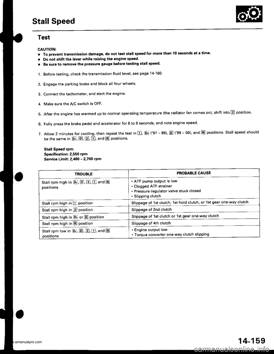
Stall Speed
Test
CAUTION:
. To prevent transmission damage, do not te3t stall speed for mors than 10 s€€onds at a time'
. Do not shift the lever while raising th€ engine spsed.
. Be sure to remove tho pressuro gauge bofore testing stall speed,
1. Before testing, check the transmission fluid level, s€e page 14-160.
2. Engage the parking brake and block all four wheels
3. Connect the tachometer, and start the engane.
4. Make sure the Ay'C switch is OFF
5. After the engine haswarmed upto normal operating temperature (the radiator fan comes on),shiftinto@ position.
6. Fully press the brake pedal and accelerator for 6 to 8 seconds, and note engine speed '
j. A|ow 2 minutes for cooling, then repeat the test in E, E ('97 - 98). E {'99 - 00}, and E positions. Stall speed should
be the same in E, E, E, tr. and E positions
Stall Speed rpm:
Specitication: 2,550 rpm
S€rvice Limit: ?,400 - 2.700 rpm
TROUBLEPROBAELE CAUSE
Stall rpm high in El, E, E, E and E
positions
ATF pump output is low
Clogged ATF strainer
Pressure regulator valve stuck closed
Slipping clutch
Stall rpm high in E positionSlippage of 1st clutch, 1st-hold clutch, or 1st gear one-way clutch
Stall rpm high in E positionSlippage of 2nd clutch
stall rpm high in E! or E positionSlippage of 1st clutch or 1st gear one-way clutch
Stall rpm high in E positionSlippage of 4th clutch
Stall rpm low in [dd, E. E, E, ana E
positions
. Engine output low
. Torque converter one-way clutch slipping
14-159
www.emanualpro.com
Page 678 of 1395

Pressure Testing
(cont'd)
Line Proslure, lst Clutch, lst.hold Clutch prsssuro Measuromont
1. Start the engine, and shift to E or @ position.
2. Run the engine at 2,000 rpm, then measure line pressure. Higher pressure may be indicated if measurements aremade in shift lever positions other than E or @ position.
shift to E ('97 - 98) or E ('99 - oo) position and hold the engine at 2.ooo rpm, then measure 1st clutch pressure.
Shift to E position and hold the engine at 2,000 rpm, then measure lst-hotd ctutch Dressure.
LOCK.UP CONTROLSOLENOID VALVEA/B ASSEMBLY
4.
PRESSURESHIFT LEVER
POSmONSYMPTOMPROBABLE CAUSEFLUID PRESSURE
StandaldService Limit
LineEor@No (or low)
line pressure
Torque converter.
ATF pump, pres-
sure regulator,
torque converter
check valve
830 - 880 kPa(8.5 * 9.0 kgflcm,,
120 - '130 psi)
780 kPa
{8.0 kgf/cm,, 'l10 psi)
1st ClutchE (97 - 98)
E ('se - oo)
No or low 1st
pressurelst Clurch
lst-hold
ClutchtrNo or low lst-
hold pressure1st-hold Clutch
14-162
www.emanualpro.com
Page 679 of 1395

znd, 3rd, and ,lth Clutch Pressurs Measuremenl'97 - 98 Modols:
1. Stan the engine, and shift to E position.
2. Run the engine at 2,000 rpm, then measure 2nd
clutch pressure.
3. Shift to E position, and hold the engine at 2'000
rpm, then measure 3rd clutch pressure.
4. Shift to E position, and hold the engine at 2,000
rpm, then measure 4th clutch pressure.
5. Shift to @ position, and hold the engine at 2,000
rpm, then measure 4th clutch pressure.
4TH CLUTCH PRESSUREINSPECTION HOLE
'99 - 00 Models:
1. Start the engine, and shift to El position.
2. Run the engine at 2,000 rpm. then measure 2nd
clutch pressure.
3. Shift to E position, and turn the Over-Drive (O/D)
OFF by pressing the O/D switch (O/O OFF indicator
light comes on).
4. Hold the engine at 2,000 rpm, then measure 3rd
clutch Pressure.
5. Turn the Over-Drive ON by pressing the O/D switch
(O/D OFF indicator light goes out), and hold the
engine at 2,000 rpm, then measure 4th clutch pres-
sure.
6. Shift to E position, and hold the engine at 2,000
rpm, then measure 4th clutch prgssure
2ND CLUTCH PRESSUREINSPECTION HOLE
3RD CLUTCH PRESSUREINSPECTION HOLE
'"r.,-ur"" "..#
- -t"1' -.
INSPECTION HOLE
PRESSURESHIFT LEVER
POSmONSYMPTOMPROBABLE CAUSE
FLUID PRESSURE
StandardServico Limit
2nd ClutchtrNo or low 2nd
pres$ure
2nd Clutch800 - 850 kPa
\A.2 - 8.1 kgtlcm2,'120 - '124 psil
760 kPa
(7.7 kgf/cm'�, 110 psi)
3rd ClutchE (97 - s8)
Elwith Over-
Drive is OFF(99 - 00)
No or low 3rd
pressure
3rd clutch
4th clutchE (97 ,98)
E (99 - oo)
No or low 4th
pressure
4th Clutch
EServo Valve or 4th
Clutch
14-163
www.emanualpro.com