Page 1516 of 2189
Connector ldentification and Wire Harness Routing
Rear Wire Harness (Halchbackl
Connector or
Terminal
Number of
CavitissLocationConnects toNotes
c601
c601
c602
c603
c604
c605
c606
c607
c608
14
20
2
2
6
Left quarter panel
Left quarter panel
Left quaner panel
Left quarter panel
Left side of cargo area
Right side of cargo area
Right quarter panel
Right quarter panel
Right quaner panel
Floor wire harness {C562}
Floor wire harness (C562)
Floof wire harness (C563)
Left rear speaker
Left outer taillight
Right outer taillight
Right rear speaker
Hatch wire harness (C761)
Hatch wire harness (C762)
Optional
Optional
G601Middle of cargo areaBody ground, via rear wire harness
*1: '96 - 98 models*2: '99 - 00 models
REAR WIRE
s\
23-46
Page 1517 of 2189
D
Rear Wire Harness {Coupe: '96 - 99 models/Sedan; '96 - 98 modelsl
Connector or
Torminal
Numbsr of
CaviiiesLocationConnects toNotes
c601
c601
c602
c603
c604
c605
c606
c609
c610
LOtl
c612
c613
c6'1 4
c616
c617
to
20
1)
1
4
2
2
2
4
Left quarter panel
Left quarter panel
Left quarter panel
Left quarter panel
Left side of trunk
Right side of trunk
Right quarter Panel
Left side of rear window
Middle of rear shelf
Middle of rear shelf
Right side of rear window
Left side of trunk
Middle of trunk
Middle of trunk
Middle of trunk
Right side of trunk
Floor wire harness (C562)
Floor wire harness (C562)
Floor wire harness (C563)
Left rear speaker
Left outer taillight
Right outer taillight
Right rear speaker
Rear window defogger (+)
High mount brake light
Trunk light
Rear window defogger (-l
Left inner taillight
Left Iicense plate light
Trunk latch switch
Right license Plate light
Right inner taillight
G601Middle of trunkBody ground, via rear wire harness
REAR WIRE HARNESS
23-47
Page 1518 of 2189

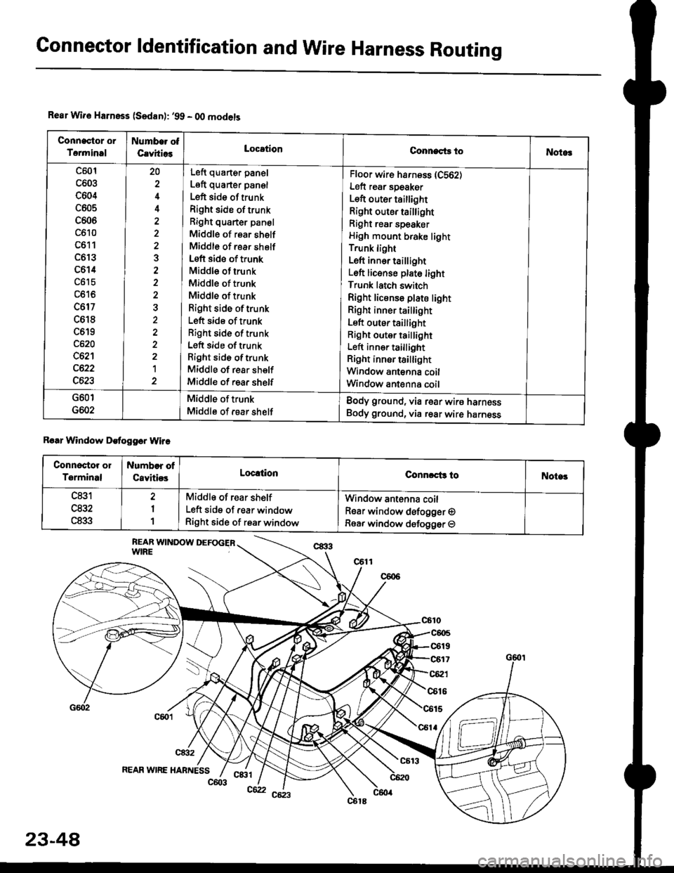
Connector ldentification and WireHarness Routing
Rear Wir€ Harnsss (Sedan): '99 - O0 models
Connactor or
Torminal
Numb€r ot
CavhiosLocationConnects toNotog
c501
c603
c604
c605
c606
c610
c611
c6r3
c614
c617
c618
c619
c620
c621
c622
c623
20
4
3
2a
1
Left quarter panel
Left quarter pan€l
Left side of trunk
Right side of trunk
Right quarter panel
Middle of rear shelf
Middle of rear shelf
Left side of trunk
Middle of trunk
Middle of trunk
Middle of trunk
Right side oftrunk
Left side of trunk
Right side of trunk
Left side of trunk
Right side oftrunk
Middle of rear shelf
Middle of rear shelf
Floor wir€ harness (C562)
Left rear speaker
Left outer taillight
Right outer taillight
Right rear speaker
High mount brake light
Trunk light
Left inn6r taillight
Left licenso plate light
Trunk latch switch
Right license plate light
Right inner tai ight
Left outer taillight
Right outer taillight
Left inner taillight
Right inner tsillight
Window antenna coil
Window ant€nna coil
G601
G602
Middle of trunk
Middle of rsar shelf
Body ground, via rear wire harness
Body ground, via rear wire harness
Roar Window Detogger Wire
Connectot or
Terminal
Numbor of
CavitiosLoc!tionConnrct3 toNote!
c831
u65Z
c833
2
1
1
Middle of rear shelf
Left side of rear window
Right side of rear window
Window antenna coil
Rear window defogger O
Rear window defogger O
REAR WIRE HABNESSc&tl
23-48
c603c62
Page 1526 of 2189
Connector ldentificationand Wire Harness Routing
Hatch Wiro Harness (Hatchbackl
Connector or
T€rminal
Number of
CavitiesLocationConnects toNotes
c761
c762
c764
c768
6
2'|
2
2
Right quaner panel
Right quaner panel
Rear of roof
Right side of hatch
Middle of hatch
Middle ot hatch
lViddle of hatch
Middle of hatch
Rear wire harness (C607)
Rear wire harness (C608)
High mount brake light
Rea. window defogger (+)
Right license light
Left license light
Rear window wiper motor
Hatch latch switch
Middle of tailgateBody ground, via tailgate wire harness
Rear Window D€fogg€r cround Wir€ (Hatchbackl
Connoctor or
Terminal
Number oI
CavitiesLocationConnects toNotes
Left side ot hatchRear window defogger (-)
G171Left side of hatchBody ground, via rear window defoggerground wire
23-56
Page 1531 of 2189
rt
SRS Main Harness
Conneclor or
Terminal
Number of
CavitiesLocationConnects toNotes
c801
c802
c803
c804
c805
c806
c807
2?
2
2
2
18
Under left side of dash
Above under-dash fuse/relaY
DOX
Right side of under-dash fuse/
relay Dox
Under left side of dash
Under right side of dash
Middle of floor
Middle of floor
Under-dash fuse/relay box (C911)
N4ain wire harness (C412)
Memory erase signal {MES) connector
Cable reel
Passenger's airbag assemblY
Dummy resastor connector
SRS unit
USA
Canada
G801Middle of floorBody ground, via SRS main harness
SRS MAIN HARNESS
23-61
Page 1560 of 2189

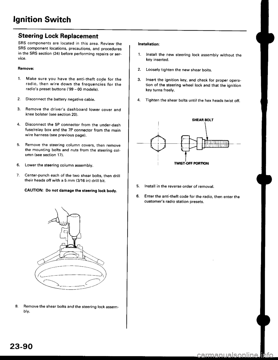
lgnition Switch
Steering Lock Replacement
SRS components are located in this area. Review theSRS component locations. precautions, and procedures
in the SRS section (24) before performing repairs or ser-vtce.
Remove:
LMake sure you have the anti-theft code for theradio, then wire down the frequencies for theradio's preset buttons ('99 - 00 models).
Disconnect the battery negative cable.
Remove the driver's dashboard lower cover andknee bolster (see section 20).
Disconnect the 5P connector from the under-dash
fuse/relay box and the 7P connector from the mainwire harness (see previous page).
Remove the steering column covers, then removethe mounting bolts and nuts from the steering col-umn (see section l7).
Lower the steering column assembly,
Center-punch each of the two shear bolts, then drilltheir heads off with a 5 mm (3/16 in) dritt bit.
CAUTION: Do not damago the steering lock body.
Remove the shear bolts and the steering lock assem,oty.
2.
1.
23-90
Installation:
l. Install the new steering lock assembly without thekey insened.
Loosely tighten the new shear bolts-
Insert the ignition key, and check for proper opera-tion of the steering wheel lock and that the ignitionkey turns freely.
Tighten the shear bolts untilthe hex heads twist off.
TWIST.OFF FORTION
Install in the reverse order of removar.
Enter the anti-theft code for the radio, then enter thecustomer's radio station presets.
sr{€aR SroLT
Page 1571 of 2189

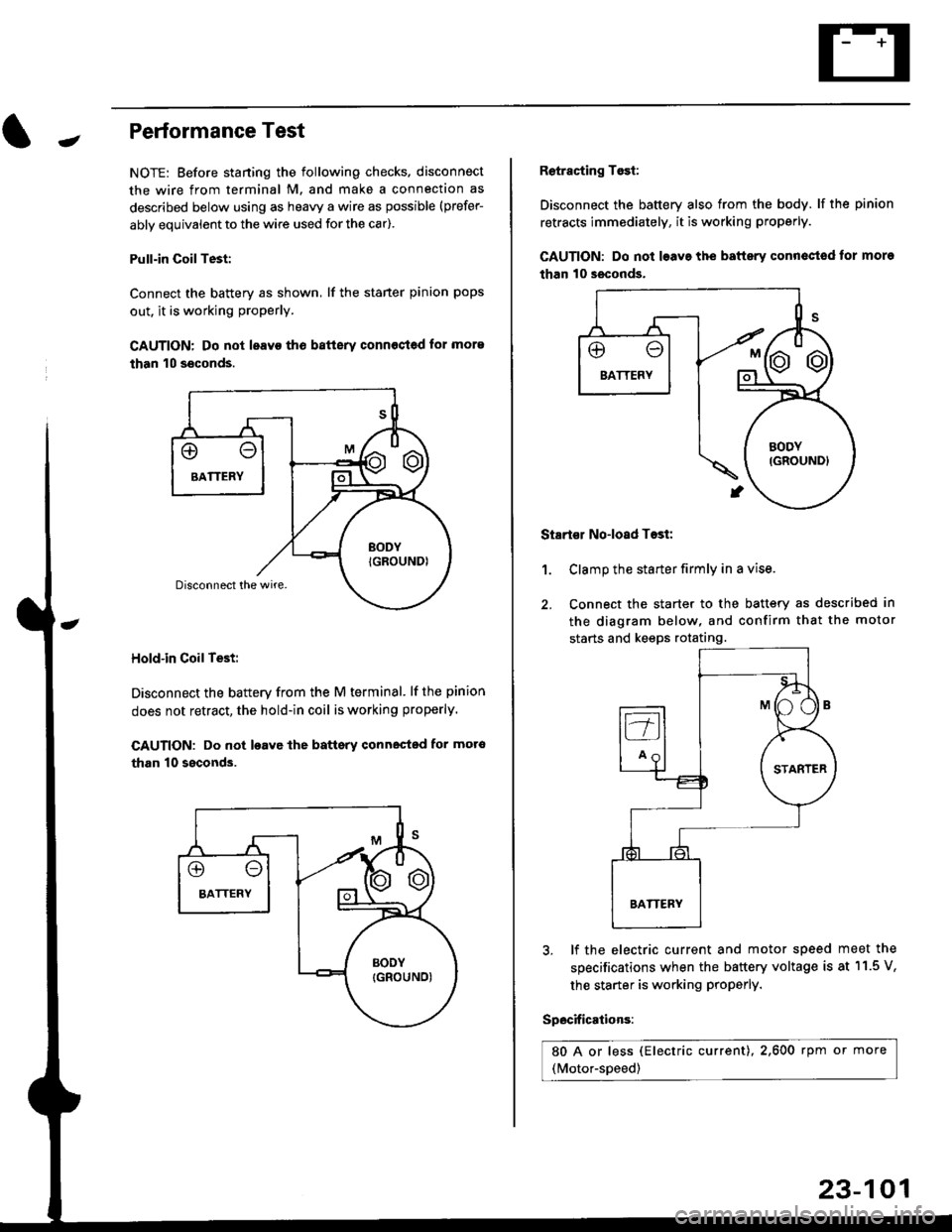
-Performance Test
NOTE: Before staning the following checks. disconnect
the wire from terminal M. and make a connection as
described below using as heavy a wire as possible (prefer-
ably equivalent to the wire used for the car).
Pull-in CoilTest:
Connect the battery as shown, lf the staner pinion pops
out. it is working proPerly.
CAUTION: Do not leavo tho batterv connost€d for more
than 10 seconds.
Hold-in Coil Test:
Disconnect the battery from the M terminal' lf the pinion
does not retract, the hold-in coil is working properly.
CAUTION: Do not loavc lhe battsry connected for mot6
than 10 ssconds.
Retracting Tosi:
Disconnect the battery also from the body. lf the pinion
retracts immediately, it is working properly.
GAUTION: Do not loave the baftery conn€ctod tor more
than 10 seconds.
Startor No-load Tost:
Clamp the starter firmly in a vise.
Connect the starter to the battery as described in
the diagram below, and confirm that the motor
starts and keeps rotating.
1.
3, lf the electric current and motor speed
specifications when the battery voltage is
the starter is working ProPerly.
Specifications:
80 A or less (Electric current),2,600 rpm or more
(Motor-speed)
meet the
at 11.5 V,
23-101
Page 1579 of 2189

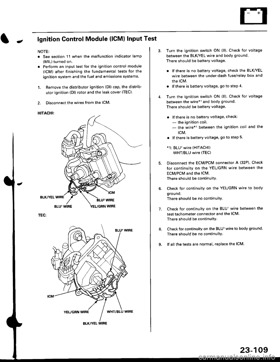
Jlgnition Control Module (lCMl Input Test
NOTE:
. See section 1'l when the malfunction indicator lamp
(MlL) turned on.
. Perform an input test for the ignition control module
(lCM) after finishing the fundamental tests for the
ignition system and the fuel and emissions systems
1. Remove the distributor ignition (Dl) cap, the distrib-
utor ignition (Dl) rotor and the leak cover (TEC).
2. Disconnect the wires from the lCM.
HITACHI:
BLK/YEL
TEC:
Turn the ignition switch ON (ll). Check for voltage
between the BLK/YEL wire and body ground.
There should be battery voltage.
. lf there is no battery voltage, check the BLK/YEL
wire between the under-dash fuse/relay box and
rhe lcM.
. lf there is battery voltage, go to step 4.
Turn the ignition switch ON (ll). Check for voltage
between the wire*r and body ground
There should be battery voltage.
. lfthere is no battery voltage, check:
- the ignition coil.
- the wire*1 between the ignition coil and the
tcM.
. lf there is battery voltage, go to step 5
*1: BLU'�wire (HITACHI)
WHT/BLU wire (TEC)
Disconnect the EcM/PCM connector A (32P). Check
for continuity on the YEUGRN wire between the
ECM/PCM and the lCM.
There should be continuity.
Check for continuity on the YEUGRN wire to body
ground.
There should be no continuity.
Check for continuity on the BLUl wire between the
test tachometer connector and the ICM
There should be continuitY.
Check for continuity on the BLUl wire to body ground.
There should be no continuity.
lf all the tests are normal, replace the ICM
7.
23-109