2000 HONDA CIVIC Body
[x] Cancel search: BodyPage 1680 of 2189
Power Mirrors
Funstion Test (cont'dl
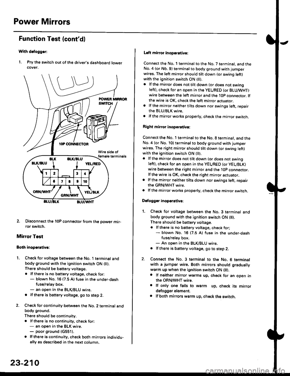
With dcfoggcr:
1. Pry the switch out ot the driver's dashboard lowercover.
2. Disconnect the 10P coonector from the oower mir-ror switch.
Mirror Test
Bolh inoparrtiv.:
1. Check for voltage between the No. 1 terminal andbody ground with the ignition switch ON flt).There should be battery voltage.. lf there is no battery voltage, check to.:- blown No. 16 (7.5 A) fuse in the under-dash
tuse/relay box.- an open in the BLVBLU wrre.
! lf thero is banery voltage, go to step 2.
2. Check for continuity b€tween the No. 2 terminal andbody ground.
There should be continuitv.. ll there is no continuity, check tor:- an open in the BLK wire.- poor ground (G5511.
. lJthere is continuity. check both mirrors individu-ally 8s described in the next column,
23-210
Laft mirror inopcrativ!:
Connect the No. 1 terminal to the No. 7 terminal. and theNo. 4 (or Nb.9) terminalto body ground with jumper
wires. The left mirror should tilt down (or swing left)with the ignition switch ON (ll).
. lf the mirror does not tilt down (o. does not swinglett), check for an open in the YEURED (or BLUMHT)wire between the left mirror and the 10p connector. lfthe wire is OK, check the left mirror actuator.a lf the mirror neither tilts down nor swings left, repairthe BLU/BLK wire.
t lf the mirror works properly, check the mirror switch.
Right mi.ror inopcrativc:
Connect the No. 1 terminal to the No. 8 terminal, and theNo.4 (or No. 10) terminalto body ground with l'umperwi.es. The right mirror should tilt down (or swing lett)with the ignition switch ON (ll).
. lf the mirror does not tilt down {or does not swingleft), check for an open in the YEURED {or YEUBLK)
wire between the right mirror and the l0P connector.lf the wire is OK, check the right mirror actuator,. lf the mirror neither tilts down nor swings left, repairthe GRN/WHT wire.o lf the mirror works properly. check the mirro. switch,
Dafoggcr inoperEtivo:
1. Check for voltage between the No. 3 terminal andbody ground with the ignition switch ON (||).
There should be battery voltage.a lf there is no battery voltage, check for;- blown No. 16 (7.5 A) luse in the under-dash
fuse/rel8y box,- An open in the BLK,iBLU wire.. It there is battery voltage, go to step 2.
2. Connsct the No. 3 tsrminal to the No. 6 terminalwith a iumpsr wire. Both mirrors should gradually
warm up when the ignition switch ON flt).a lf neither mirror warms up, check for an open inthe ORN/WHT wire.. It only on€ lails to warm up, check its mirrordsfogger elem6nt.. lf both mirrors warm up, check ths switch.
Page 1707 of 2189
Funstion Test
CAUTION: Bo careful not to damago the moonroof switch
or ths driv6r's dashboard lowsr cover when prying the
3witch out.
NOTE: Check the No. 51 (20 Al fuse in the under-hood
tuse/relay box and No.24 (7.5 A) fuse in the under-dash
fuse/relay box, before testing.
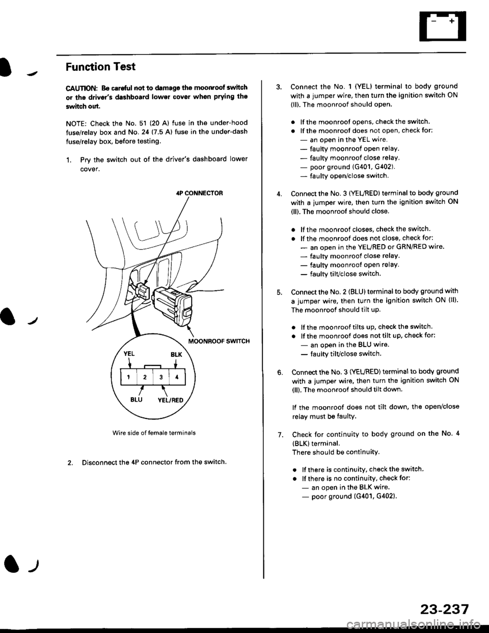
1. Prv the switch out of the driver's dashboard lower
cover.
swtTcH
Wire side of female terminals
2. Disconnect the 4P connector from the switch
4P CONNECTOR
l-t
23-237
Connect the No. 1 (YELI terminal to body ground
with a jumper wire, then turn the ignition switch ON
(ll). The moonroof should open.
. lf the moonroot opens, check the switch.
. lf the moonroot does not open, check for:
- an open in the YEL wire.
- faulty moonroof open relay.
- faulty moonroof close relay,
- poor ground (G401, G402).- fa u lty open/close switch.
Connect the No. 3 (YELnED) terminal to body ground
with a jumper wire. then turn the ignition switch ON
(ll). The moonroof should close.
. lf the moonroof closes. check the switch.
. lf the moonrool does not close, check for:
- an open in the YEURED or GRN/RED wire'
- faulty moonroof close relaY.
- faulty moonroot oPen relaY.
- faulty tilvclose switch.
Connect the No. 2 (BLU) terminal to body ground with
a jumper wire, then turn the ignition switch oN (ll).
The moonroof should tilt up.
. lf the moonroof tilts up, checkthe switch.
. lf the moonroof does nottilt up, checkfor:
- an open in the BLU wire.
- taulty tilvclose switch
Connect the No. 3 (YEURED) terminal to bodY ground
with a jumper wire, then turn the ignition switch ON
(ll), The moonroof should tilt down.
lf the moonroof does not tilt down, the open/close
relay must be taulty.
Check for continuity to body ground on the No. 4
{BLK}terminal.
There should be continuity.
. lf there is continuity, check the switch
. lf there is no continuity, check for:
- an open in the BLK wire
- poor ground (G401, G402).
6.
7.
Page 1746 of 2189
Precautions/Procedu res
SRS Unit Precautions
Take extra care when painting or doing body work inthe area below the dashboard. Avoid direct exDosureof the SRS unit or wiring to heat guns, welding. orsprayang equipment.
Disconnect the airbag connector(s) before discon-necting SRS harness connectors (see page24-1|1J.
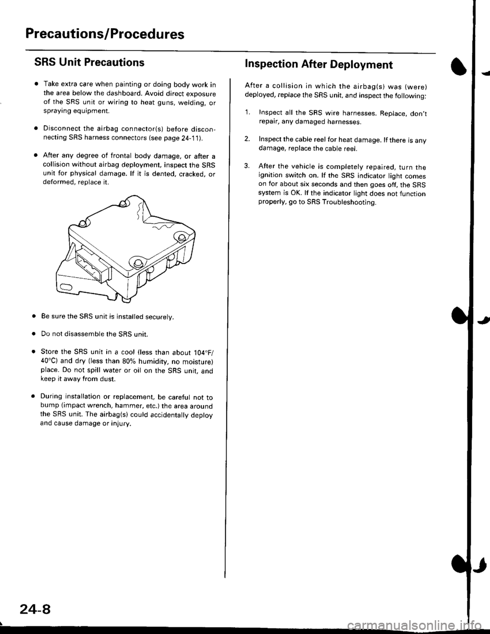
After any degree of frontal body damage, or after acollision without airbag deployment, inspect the SRSunit for physical damage. lf it is dented. cracked, ordeformed, replace it.
Be sure the SRS unit is installed securely.
Do not disassemble the SRS unit.
Store the SRS unit in a cool (less than about 104.F/40"C) and dry (less than 80% humidity, no moisture)place. Do not spill water or oil on the SRS unit, andkeep it away from dust.
During installation or replacement, be careful not tobump (impact wrench, hammer, etc.) the area aroundthe SRS unit. The airbag(s) could accidentally deptoyand cause damage or injury.
24-8
Inspection After Deployment
After a collision ln which the airbag(s) was (were)
deployed, replace the SRS unit, and inspect the following:
1. Inspect all the SRS wire harnesses. Replace. don,trepair, any damaged harnesses.
2. Inspect the cable reel for heat damage. lf there is anydamage, replace the cable reel.
3. After the vehicle is completely repaired, turn theignition switch on. lf the SRS indicator light comeson for about six seconds and then goes off. the SRSsystem is OK. lf the indicator light does not functionproperly, go to SRS Troubleshooting.
Page 1747 of 2189
)
Wiring Precautions
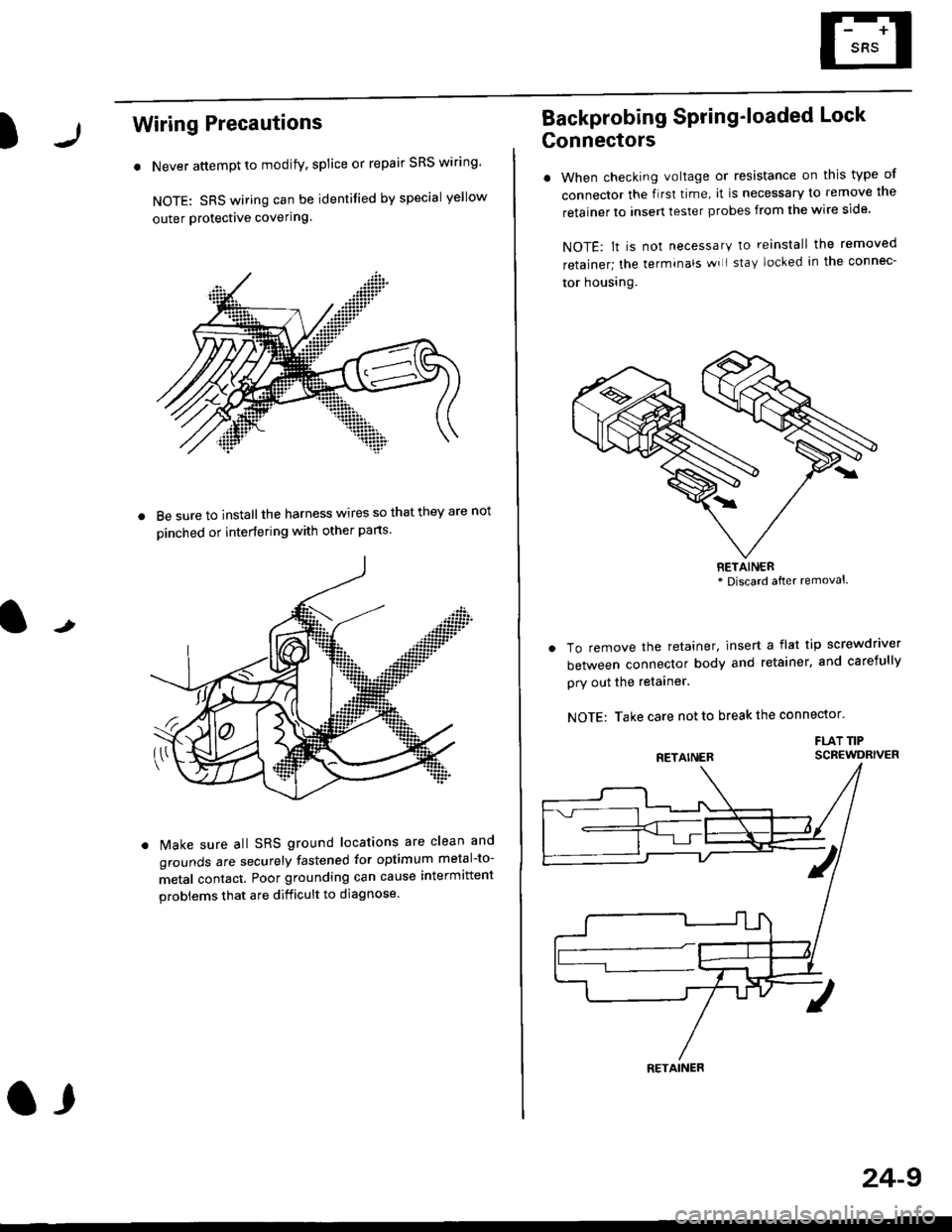
. Never attempt to modify, splice or repair SRS wiring'
NOTE: SRS wiring can be identified by special yellow
outer Protective covering.
8e sure to install the harness wires so that they are not
oinched or interfering with other parts.
t
Make sure all SRS ground locations are clean and
grounds are securely fastened for optimum metal-to-
metal contact. Poor grounding can cause intermittent
problems that are difficult to diagnose.
a,
24-9
Backprobing Spring'loaded Lock
Gonnectors
. When checking voltage or resistance on this type of
connector the flrst time, it is necessary to remove lne
retainer to insert tester probes from the wire side.
NOTE: lt is not necessary to reinstall the removed
retainer; the terminals wi I stay locked in the connec-
tor housrng.
To remove the retainer, insert a flat tip screwdriver
between connector body and retainer, and carefully
pry out the retainer.
NOTE: Take care not to break the connector.
FLAT TIPSCBEWDRIVER
RETAINER* Discard after removal.
RETAINER
Page 1785 of 2189
)
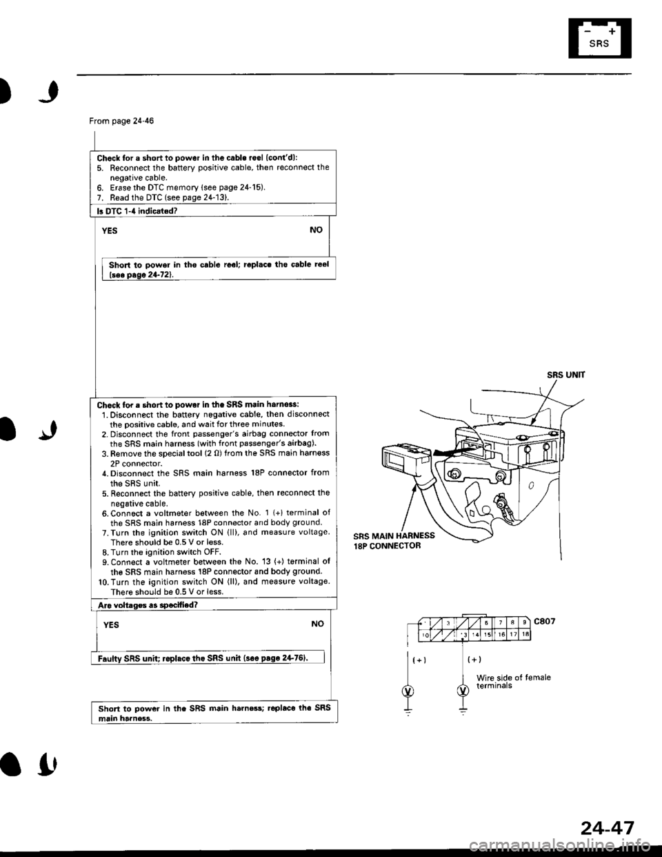
From page 24-46
Chock for a short to power in the cabls roel lcont'dl:5. Reconnect the battery positive cable, then reconnect thenegative cable.6. Erase the DTC memory lsee page 24-15).7. Read the DTC (see pa1e24-131.
b DTC 1-4 indicat€d?
YESNO
Short to power in tho cable reel; roplac. tho cable reel
lsee Dase 24-721.
Chock for e short to powot in the SRS main hornoas:
1. Disconnect the battery nogative cable, then disconnect
the positive cable, and wait for three minutes.2- Disconnect the front passenger's airbag connector lrom
the SRS main harness (with front passenger's airbag).
3. Remove the special tool (2 0) trom the SRS main harn€ss
2P connector./t. Disconnect the SRS main harness 18P connector from
the sRs unit.5. Reconn6ct the battery positive cable, then reconnect the
negative cable.6. Connect a voltmeter between the No. 1 {+i terminal of
the SRS main harness 18P connector and body ground.
7. Turn the ignilion switch ON lll), and measure voltageThere should be 0.5 V or less.8. Turn the ignition switch OFF.9. Connect a voltmeter between the No. 13 (+) torminal ol
the SRS main harness 18P connector 8nd body ground.
lO.Turn the ignition switch ON (ll), and measure voltage
There should be 0.5 V or less.
Aro voltrges a3 specified?
YESNO
Fauftv SRS unh; roplacc tho SRS unh {soe pago 2+761'
Short to power in the SRS main h.rness; .eplace rhe SRS
main harness.
SRS UNIT
IJ
a0
24-47
Page 1833 of 2189
How To Use This Manual
Troubleshooting Tests (cont'd)
4. Turn on the short finder. This creates a
pulsing magnetic field around the wiring
between the fuse box and the short.
5. Beginning at the fuse box, slowly move
the short finder along the circuit wiring.
The meter will show current Dulses
through sheet metal and body trim. As
long as the meter is between the fuse and
lhe short, the needle will move with each
current pulse. Once you move the meter
past the point of the short, the needle will
stop moving. Check the wiring and
connectors in this area to locate the cause
of the short.
co
Page 2077 of 2189
How the Circuit Works
The two outside mirrors are controlled by the power
mirror switch. Each mirror has two reversible
motors: one motor moves lhe mirror uo and down
and the other motor moves the mirror left and right.
The power mirror switch contains four switches to
control mirror adjustment, and a switch lo select
the left or right mirror. With the ignition ON (ll),
battery voltage is supplied to the power mirror
switch. The mirror selector switch directs voltage
Irom the direction switches to either the left or rioht
mtrror.
Mirror Up
When you press the "up" edge of the mirror
adjustment button, voltage is supplied from one of
the UP switch contacts to both mirrors. With the
mirror select switch in the LEFT or RIGHT Dosition.
ground is provjded for the corresponding up/down
motor through the opposite UP switch contact.
Battery voltage is supplied to the mirror up/down
motor which then tilts the selected mirror uo.
Mirror Down
When you press the "down" edge of the mirror
adjustment button, ground is provided through one
of the DOWN switch contacts to both mirrors.
With the mirror select switch in the LEFT or RIGHT
position, voltage is supplied to the corresponding
up/down motor through the opposite DOWN switch
contact. Battery voltage is supplied to the mirror
up/down motor which then tilts the selected
mtrror down.
Mirror Left
When the mirror select switch is in the LEFT or
RIGHT position, and you press the "lett" edge of the
mirror adjustment button, voltage is supplied to both
corresponding mirror motors through one of the
LEFT switch contacts. Ground is provided for the
corresponding lefvright motor through the opposite
LEFT switch contact, 8attery voltage is supplied to
the mirror left /right motor which then tilts the
selected mirror left.
I,J
141-3
Mirror Right
When the mirror select switch is in the LEFT or
RIGHT position, and you press the '?ight" edge of
the mirror adjustment button, ground is provided to
both corresponding mirror motors through one of
the RIGHT switch contacts. Voltage is supplied to
the corresponding leruright motor through the
opposite RIGHT switch contact. Battery voltage is
supplied to the mirror left /right motor which then
tilts the selected mirror right.
Mirror Detoggers
With the ignition switch in ON (ll), battery voltage is
supplied to the mirror defogger switch. When you
press the mirror defogger switch ON, voltage is
supplied to both mirror defoggers, causing them to
heat up and remove any fog from the mirrors. The
opposite side of each defogger grid is connected to
g rou no.
Refer to the Service Manual (Section 23,
Body Electrical) for specific tests and
troubleshooting procedures.
Page 2141 of 2189
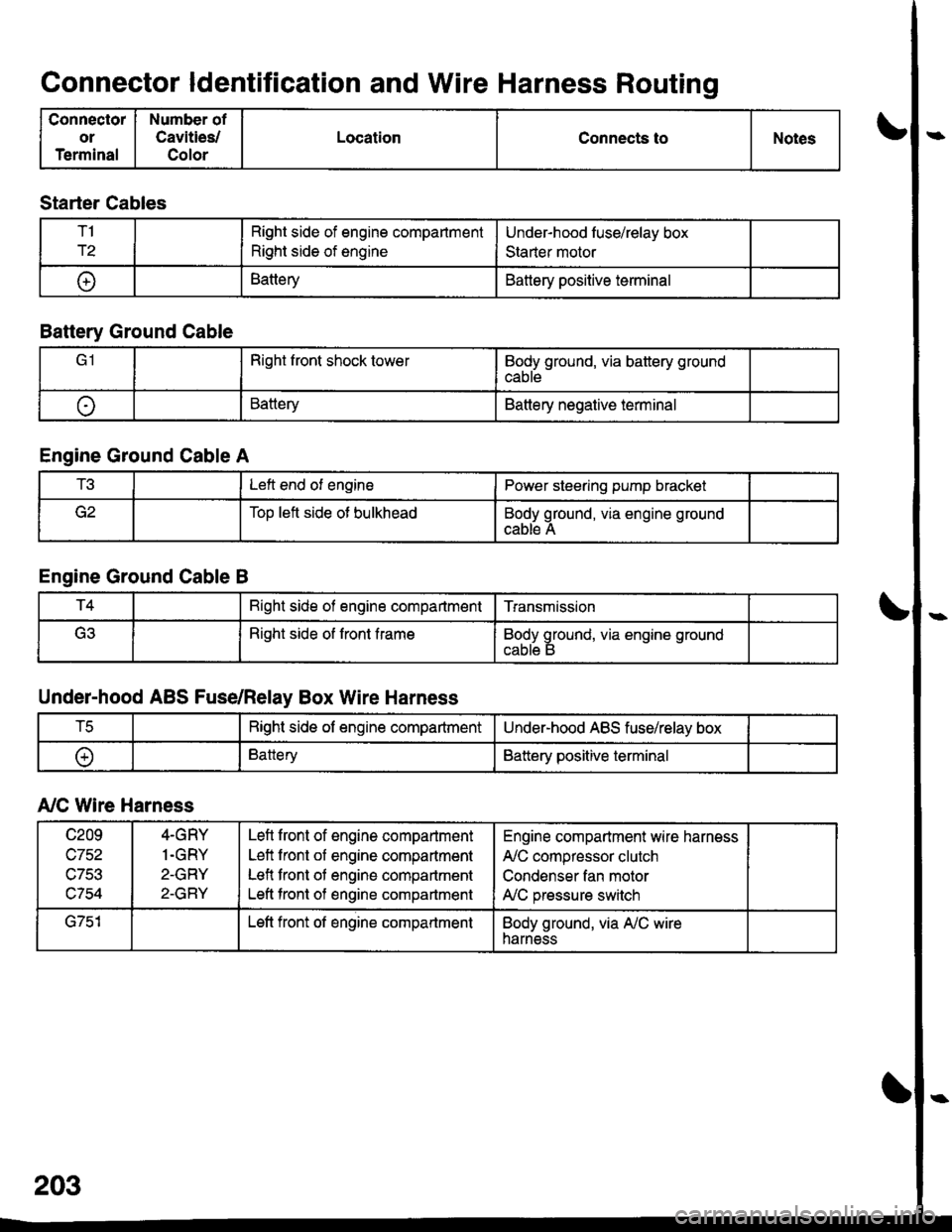
Connector ldentification and Wire Harness Routing
Connector
or
Terminal
Number of
Cavities/
Color
LocationConnects toNotes
Starter Cables
T1
r2
Right side of engine compartment
Right side of engine
Under-hood luse/relay box
Staner motor
t+lBatteryBattery positive terminal
Battery Ground Cable
Right front shock towerBody ground, via battery ground
cable
oBatteryBattery negative terminal
Engine Ground Cable A
t!tLeft end of enginePower steering pump bracket
Too left side ot bulkheadBody ground, via engine ground
cable A
Engine Ground Cable B
T4Bight side of engine compartmentTransmission
(ritRight side of front frameBody ground, via engine ground
Under-hood ABS Fuse/Relay Box Wire Harness
tcRight side of engine compartmentUnder-hood ABS fuse/relay box
oBatteryBattery positive terminal
A,/C Wire Harness
c209
wtJl/,\-7Ee
c754
4-GRY
1.GRY
2-GRY
2-GRY
Lefl front of engine compartment
Left front of engine compartment
Lefl front of engine compartment
Left tront of engine compartment
Engine compartment wire harness
A,/C compressor clutch
Condenser fan motor
A,/C pressure switch
G751Left front of engine compartmentBody ground, via A,/C wireharness