Page 1441 of 2189
A/C System
CONDENSER FAN RELAY 4P SOCKET
A/C system does not come on
{comDressor and fan).
Check the No. 56 fuse in theunder'hood fuse/relay box andthe No. 17 fuse in the under-dashfuse/relay box.
ReDlace the fus6{s}, and recheck.
Check for tn open in the wire:
1. Remove the condenser lanrelay from the u nderhood
luse/relay box.2. Turn the ignition switch ON {lli.3- Measure the voltage betweenthe No. 4 terminal of the condenser fan relav 4P socketand body ground.
Repair open in the wire between
the No. 17 fuse and the con-denser fan r6lay,
Check the under-hood fus€/r6laybox:Measure the voltage between the
No. 2 terminal of the condenser
fan relay 4P socket and bodyground,
YES
Io page 22-18
(cont'd)
Page 1442 of 2189
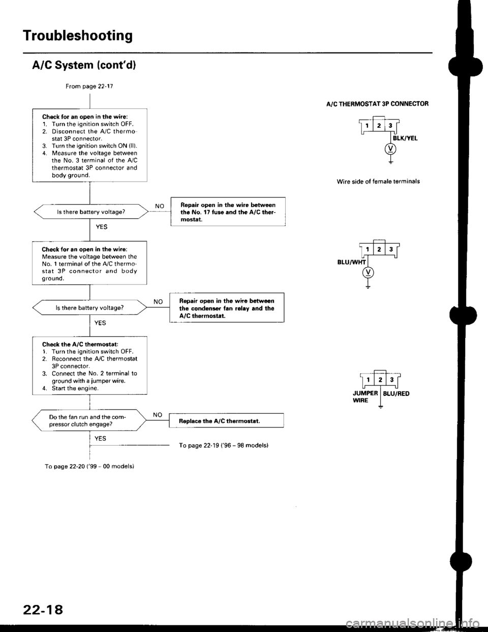
Troubleshooting
A/C System (cont'd)
From page 22-11
. _Ff,, __
I11213[
,r,il*"-T",-.r-'..owrRE I
To page 22-19 1'96 - 98 models)
A/C THERMOSTAT 3P CONNECTOR
Wire side oI female terminals
Check tor an open in the wire:1. Turn the ignition switch OFF.2. Disconnect the A/C thermostat 3P connector.3. Turn the ignition switch ON (ll).
4. Measure the voltage betweenthe No. 3 terminal of the Ay'Cthermostat 3P connector andbody ground.
Repai. open in the wire betweentho No. 17 tuso and the A/C the.-mostat.
Check loi an open in the wi.e:Measure the voltage between theNo. 1 terminal of the A,/C thermostat 3P connector and bodyground,
Ropair open in the wire betwoenthe condedlo. lan rolay and theA/C thormostat.
ls there battery voltage?
Check the A/C th6rmostat:1. Turn the ignition switch OFF.2. Reconnect the A,/C thermostat3P connector.3. Connect the No. 2 terminal toground with a iumperwire.4. Start the engine.
Do the fan run and the com-pressor clutch engage?
To page 22-20 ('99 - 00 models)
22-18
Page 1443 of 2189
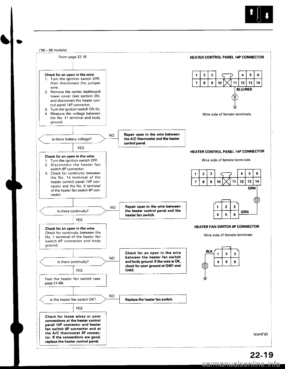
Ftom page 22 18
Check tor an open in the wire:1. Turn the ignition switch OFF,then disconnect the iu mper
2. Remove the center dashboardlower cover lsee section 20),
and disconnect the heater con'
trol panel 14P connector.
3. Turn the ignition switch ON (ll).
4. Measure the voltage betweenthe No. 11 terminal and bodyground.
Repair op6n in the wire bstween
the A/C th€rmostat and th6 hoater
control panel.
Check lor an open in the wire:
1. Turn the ignition switch OFF.2. Disconnect the heater Ian
switch 6P connector,3. Check for continuity between
the No. 14 terminal of theheater control panel 14P con_nector and the No.6 terminalof the heater fan switch 6P con-nector.
Repair open in the wiro betweGnthe heal.r control Panel and theheater fan switch.
Check for an open in thG wire:Check for continuity between theNo. 1 terminal of the heater lanswatch 6P connector and bodYground.
Chock tor an open in tho wir€
between the heater lan switch
and body ground. lf the wire is OK,check for poor ground at G401 sndG402.
ls there continu;ty?
ReDlace the heater tan switch.ls the heater fan switch OK?
Check for loose wiaes or poor
connections at the heater controloanel 14P connoctor and hoetertan 3witch 5P conn€clor and atthe A/C thermostet 3P connec-tor. ll the connections are good,
raplace the heator control Panel.
r'oA - qe m^.lalal
HEATER CONTROL PANEL lilP CONNECTOR
tra6
7II'o lx't1121314
BLU/RED
Wire side of female terminals
HEATER CONTROL PANEL 1'P CONNECTOR
Wire side of female terrninals
HEATER FAN SW]TCH 6P CONNECTOR
Wire side of female terminals
(cont'd)
12;--?45
7I10X'll121314
GRN
123
a56GRN
22-19
Page 1444 of 2189
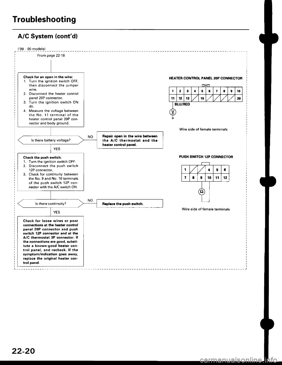
Troubleshooting
('99 00 models)
From page 22 18
Check lor an open in the wire:1. Turn the ignition switch OFF,then disconnect the ju mper
2. Disconnect the heater controlpanel 20P connector.3. Turn the ;gnition switch ON{
i.4. Measure the voltage betweenthe No. 11 terminal of theheater control panel 20P con-nector and body ground.
Ropai. opan in tho wira batwaonthe A/C thermostat and thehoater control oanol.ls there battery voltage?
Check the push switch:1. Turn the ignition switch OFF.2. Disconnect the push switch12P connector.3. Check for continuity betweenthe No. I and No. 10 terminalsof the push switch 12P con-nector with the A/C switch ON.
Check for loose wi.es or poor
connections el the hgater controlpanel 20P connector and pushswitch 12P connector and at theA/C thermostat 3P connector. Ittha connections are good, substi-tute a known-good heatea con-trol pan€|, and recheck. lf thesymptom/indication goe3 away,replace lhe original healer con-trol oan€|,
HEATER CONTROL PANEL anP CONNECTOR
Wire side of temale terminals
PUSH SW]TCH 12P CONNECTOR
Wire side of female terminals
,/1,/156
7819t01112
I
I
I
Page 1473 of 2189
Troubleshooting
ll.
Tips and Precautions
Bef ore Troubleshooting
. Check applicable fuses in the appropriate fuse/relay
box.
. Check the battery for damage, state of charge, and
clean and tight connections.
. Check the alternator belt tension.
CAUTION:
. Do not quick-charge a battery unless the battery
ground cable has been disconneqted, otherwise you
will damage the alternator diodes.
. Do not attempt to crank the engine with the battery
ground cable loosely connecled or you will severely
damage the wiling,
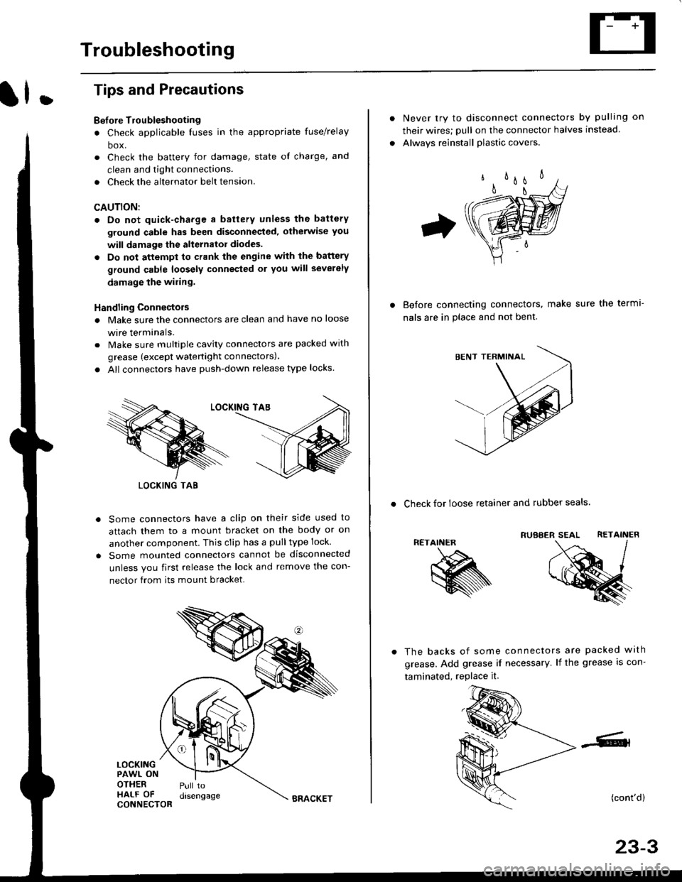
Handling Connectois
. Make sure the connectors are clean and have no loose
wire terminals.
. Make sure multiple cavity connectors are packed with
grease (except watertight connectors)
. All connectors have push-down release type locks.
Some connectors have a clip on their side used to
attach them to a mount bracket on the body or on
another component. This clip has a pulltype lock.
Some mounted connectors cannot be disconnected
unless you first release the lock and remove the con-
nector from its mount bracket.
LOCKINGPAWL ONOTHERHALF OFCONNECTOR
Pull todrsengage
LOCKING TAB
BRACKET
Never try to disconnect connectors by pulling on
their wires; pull on the connector halves instead
Alwavs reinstall plastic covers.
Before connectang connectors,
nals are in place and not bent.
make sure the terml-
. Check for loose retainer and rubber seals.
RETAINER
The backs of some connectors are packed with
grease. Add grease if necessary. lf the grease is con-
taminated, replace it.
(cont'd)
23-3
Page 1484 of 2189
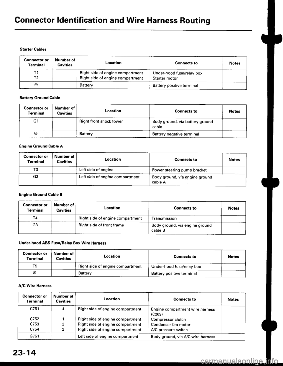
Connector ldentification and Wire Harness Routing
Connector or
Terminal
Number of
CavitiesLocalionConnec{s toNotes
T,I
r2
Right side of engine compartment
Right side of engine compartment
Under-hood fuse/relay box
Starter motor
BatteryBattery positive terminal
Starter Cables
A/C Wire Harness
Battery Ground Cable
Connector or
Terminal
Number of
CavitiesLocationConn€cts toNotos
Right front shock towerBody ground, via battery ground
caDte
oBafteryBattery negative terminal
Engine Ground Cable A
Conn€qtor or
Terminal
Number ot
CavitiosLocationConnects toNoles
T3Left side of enginePower steering pump bracket
G2Left side of engine compartmentBody ground, via engine ground
cable A
Engine Ground Cable B
Connector or
Terminal
Number of
CavitiesLocationConnecls toNoles
T4Right side of engine compartmentTransmission
Right side of front frameBody ground, via engine ground
cable B
Under-hood ABS Fusa/Relay Box Wire Harness
Connector or
Tgrminal
Number oI
CavitiesLocationConneqts toNotes
T5Right side of engine compartmentUnder-hood fuse/relay box
@BaneryBattery positive terminal
Connector or
Terminal
Number of
CavitiesLocationConnects toNotes
c753
c754
1
2
Right side of engine compartment
Right side of engine compartment
Right side of engine compartment
Right side of engine compartment
Engine compartment wire harness(c209)
Compressor clutch
Condenser fan motor
A,/C pressure switch
Left side of engine compartmentBody ground, via A,/C wire harness
23-14
Page 1498 of 2189
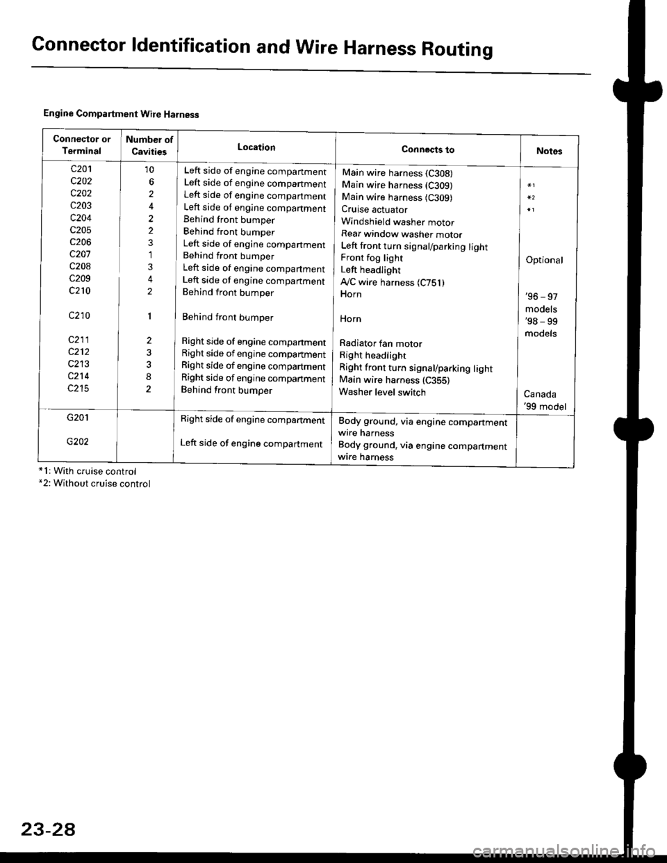
Connector ldentification and WireHarness Routing
Engine Compartment Wire Harness
conneqtor of
Terminal
Number of
CavitiesLocationConnects toNotes
c201
c202
c202
c203
c204
c205
c206
c207
c208
c209
c210
c210
c211
c212
c213
c214
c215
10
6
2
2
2
1
3
2
1
2
8
Left side of engine companment
Left side of engine companment
Left side of engine companment
Left side of engine compartment
Behind front bumper
Behind front bumper
Left side of engine compartment
Behind front bumper
Left side of engine compartment
Left side of engine companment
Behind front bumper
Behind front bumper
Right side of engine compartment
Right side of engine compartment
Right side of engine compartment
Right side of engine compartment
Behind front bumper
Main wire harness (C308)
Main wire harness (C309)
Main wire harness {C309)Cruise actuator
Windshield washer motor
Rear window washer motor
Left front turn signal/parking lightFront fog light
Left headlight
Ay'C wire harness 1C751)Horn
HOrn
Radiator fan motor
Right headlight
Right front turn signal/parking lightMain wire harness (C355)
Washer level switch
Optional
'96 - 97
models'98 - 99
models
Canada'99 model
G201
G202
Right side of engine compartment
Left side of engine compartment
Body ground, via engine compartmentwire harness
Body ground, via engine compartmentwrre harness*1r With cruise control*2: Without cruise control
23-2A
Page 1500 of 2189
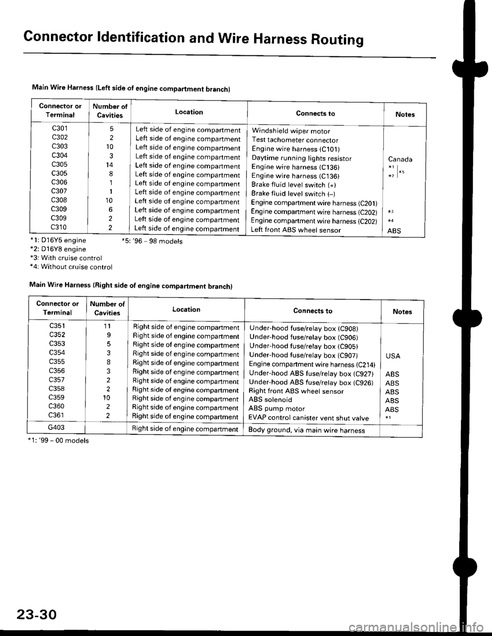
Connector ldentification and Wire Harness Routing
Main Wire Harness lLeft side ot engine compartment branchl
Connector or
Terminal
Number of
CavitiesLocationConnects toNotes
c301
c302
c303
c304
c305
c305
c306
c307
c308
c309
c309
c310
5
2
10
3
14
8
1
I
10
2
2
Left side of engine compartment
Left side of engine compartment
Left side of engine companment
Left side of engine compartment
Left side of engine compartment
Left side of engine compartment
Left side ot engine companment
Left side of engine companment
Left side of engine compartment
Left side of engine companment
Left side of engine companment
Left side of engine companment
Windsh ield wiper motor
Test tachometer connector
Engine wire harness (C101)
Daytime running lights resistor
Engine wire harness (C136)
Engine wire harness (C136)
Brake fluid level switch (+)
Brake fluid level switch (-)
Engine compartment wire harness (C201)
Engine companment wire harness (C202)
Engine compartment wire harness (C202)
Left front ABS wheel sensor
Canada
;|.'
ABS*lr D'16Y5 engine *5:'96 9g models*2: D16Y8 engine*3: With cruise control*4r Without cruise control
*1: '99 - 00 models
Main Wire Harness (Right side of engine compartment branch)
Connector or
Terminal
Number of
CavitiesLocationConnects toNotes
c353
c354
c355
c356
c357
c359
c360
11
3
I
3
2
2'10
2
2
Right side of engine compartment
Right side of engine companment
Right side of engine companment
Right side of engine compartment
Right side of engine compartment
Right side of engine companment
Right side of engine compartment
Right side of engine compartmentRight side of engine compartment
Right side of engine compartment
Right side of engine compartment
Under-hood fuse/relay box (CgoB)
Under-hood fuse/relay box (C906)
Underhood fuse/retay box (C905)
Under-hood tuse/relay box (C907)
Engine companment wire harness {C214)Under-hood ABS fuse/relay box {C927)Under-hood ABS fuse/retay box (C926)
Right front ABS wheel sensor
ABS solenoid
ABS pump motor
EVAP control canister vent shut valve
USA
ABS
ABS
ABS
ABS
ABS
G403Right side of engine compartmentBody ground, via main wire harness
23-30