Page 1409 of 2189

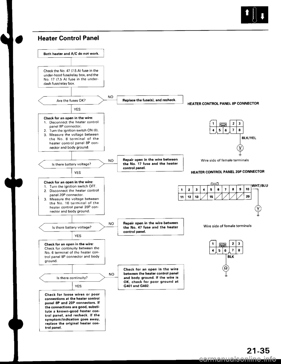
Both heater and A/C do nol work.
checkthe No.47 (7.5 A)fuse in the
under-hood fuse/relay box, and theNo. 17 {7.5 A) fuse in the under-
dash fuse/relay box.
ReDlace the tuse{s), and recheck.
Check lor an open in the wire:
1. Disconnect the heater controlpanel 8P connector,2. Turn the ignition switch ON (ll).
3. Measure the voltage between
the No. I terminal of the
heater control panel 8P con-
nector and body ground.
Repair open in the wire betweenthe No. '17 luse and th6 heatercontrol oanel,ls there battery voltage?
Check for an open in the wire:
1. Turn the ignition switch OFF.
2. Disconnect the heater controlpanel20P connector.3. Measure the voltage lletweenthe No. 10 terminal of theheater control Panel 20P con-nector and body ground.
Repair op6n in the wir€ between
the No. il7 tuse and the heater
controloanel,ls there battery voltage?
Check for an open in the wite:Check for continuity between theNo. 6 terminal of the heater con
trol panel 8P connector and bodyground.
Ch6ck tor an open in lhe wire
betwoen the heator control Paneland bodv ground. lf the wire isOK, check for poor ground atG401 and G402.
ls there continuity?
Check for looso wires or Poolconneciions at the heater controloanel 8P and 20P connectors. lf
the connections are good, substi'
tute a known-good heat€r con-trol Danel, and recheck. lI thesymptom/indication goes awaY,r6place the original h€ater con-troloanel.
HEATER CONTROL PANEL 8P CONNECTOR
BLK/YEL
Wire side of female terminals
HEATER CONTROL PANEL 2OP CONNECTOR
Wire side of temale terminals
I2
1578
BLK
o
1
4I
v
Page 1424 of 2189
Mode Control SwitchPower Transistor
Test -'96 - 98 Models
Check for continuity between the terminals accordinq tothe table below.
Terminal
Position't071
Heato-o
HeaVDefo---o
Defo--o
VentG-o
HeaVVento--o
1
;l t
4
789
21-50
Test -'99 - 00 Models
1. Disconnsct the 3P connector from the oower tran-stsror.
2, Carefully release the lock tab on the No. 2 terminal inthe 3P connector, then remove the terminal and insu-late it from body glound.
Connect a 1.2 - 3.4 W bulb between the No. 1 andthe No. 2 cavity on the 3P connector.
Reconnect the 3P connector to the power translstor.
Turn the ignition switch ON fll), and check that theblower motor runs.
12V 1.2-3,1W
No. 1 laLU/aLK)
Page 1434 of 2189
Troubleshooting
Condenser Fan (cont'd)
CONDENSER FAN RELAY 4P SOCKET
CONDENSEB FAN 2P CONNECTORWire side of female terminals
-=F_
l!.lI slx
@I
Check tor an opon in the wi.o:1. Disconnect the jumper wire.2. oisconnect the condenser tan2P connector.3. Check for continuity betweenthe No. 1 terminal of the con-denser fan relay 4P socket andthe No. 1 terminal of the con-denser fan 2P connector.
Rapair op6n in the wirs bgtwconthe condcnsor tan rclay and thecondgnlar fan.
ls there continuity?
Check to. en open in the wire:Check for continuity between theNo. 2 terminal ot the condenserfan 2P connector and bodyground.
Check Ior rn opon in th6 wirebctwoen the condcnser tan andbody ground, lf iho wirc ii OK,chcck for poor ground at G751.
ls there continuity?
Replaco the condense. fan motor.
22-10
Page 1435 of 2189
Check the diode:1. Disconnect the iumPer wire
2. Remove the A/C diode from
the under hood fuse/relaY box
3. Check for current flow in both
directions between the A and
B terminals.
ls there current flow in onlY
one direction?
Chock for an open in the wire:
1. Turn the ignition switch ON(ll).
2. Measure the voltage between
the No. 2 terminal of the AJC
diode 2P socket and body
ground.
Repair opon in the wire betwe€n
the No. 17 luse and the A/c
diode.ls there battery voltage?
B()-=iFA
A/C DIOOE 2P SOCKET
Page 1436 of 2189
Troubleshooting
Compressor
COMPRESSOR CLUTCH RELAY.P SOCKET
JUMPERWIRE
check the No. 56 (20 A) fuse in theunder'hood fuse/relay box, and theNo. 17 (7.5 A) fuse in the under,dash fuse/relay box.
Replace the fussls), and .echeck.
Remove the compressor clutchrelay, and test it {see page 22 21).
Check th6 und€r-hood tu3e/reby
Measure the voltage between theNo. 2 terminal of the compressorclutch relay 4P socket and bodyground.
Check the compressor clutchpow€r supply circuit:Connect the No. 1 and No. 2 termi-nals of the compressor clutch relay4P socket with a jumper wire.
Does the compressor clutch click?fo page 22-13
To page 22 14
22-12
Page 1438 of 2189
![HONDA CIVIC 2000 6.G Workshop Manual Troubleshooting
Compressor lcontdl
COMPRESSOR CLUTCH RELAY4P SOCKET
l--;l
12 |---r--]l.l3 |L-J--J
] BLK/YEL
A(v)
!
ECM/PCM CONNECTOR A I32P}
Wire side of female terminats
*Howto use the backprobe set HONDA CIVIC 2000 6.G Workshop Manual Troubleshooting
Compressor lcontdl
COMPRESSOR CLUTCH RELAY4P SOCKET
l--;l
12 |---r--]l.l3 |L-J--J
] BLK/YEL
A(v)
!
ECM/PCM CONNECTOR A I32P}
Wire side of female terminats
*Howto use the backprobe set](/manual-img/13/6068/w960_6068-1437.png)
Troubleshooting
Compressor lcont'dl
COMPRESSOR CLUTCH RELAY4P SOCKET
l--;l
12 |---r--]l.l3 |L-J--J
] BLK/YEL
A(v)
!
ECM/PCM CONNECTOR A I32P}
Wire side of female terminats
*Howto use the backprobe setsConnect the backprobe adapters to the stackang patch cords, andconnect the cords to a multimeter. Using the wire insulation as aguide for the contoured tip of the backprobe adapter, gently slidethe tip into the connector from the wire side until it comes in con-tact with the terminalend ofthe wire (see section 11).
Frcm page 22-12
To page 22-15
Check Ior an open in the wire;1. Disconnecl the jumper wire.2. Turn the ignition swatch ON (ll).
3. l\4easure the voltage betweenthe No. 4 terminal of the com-pressor clutch relay 4P socketand body ground.
Repair open in the wire betw€enthe No. 17 fuso and the compres-sor clutch relav.
Check for an open in the wira:1. Turn the ignition switch OFF,then reinstall the compressorclutch relay.2. Make sure the A/C switch isOFF, then turn the ignitionswitch ON (ll).
3. Using a *Backprobe Set (T/N07SAZ 0010004), measurethe voltage between the No.17 terminal oI the ECM/PCMconnector A (32P) and bodyground with the ECM/PCMconnectors connected.
Repair open in the wirc betweonthe compressor clutch relay andthe ECM/PCtvt.
ls there battery voltage?
Page 1439 of 2189
Frcm page 22-14
Check lor an open in the wire:1. Turn the ignition switch OFF.
2. Disconnect the A/C pressure
switch 2P connector.3. Turn th ignition switch ON lll).4. Measure the voltage between
the No. 1 terminal of the AJCpressure switch 2P conneclorand body ground.
Check the A/C pressure switch:1. Turn the ignition switch OFF.
2. Check for continuity between
the No. 1 and No. 2 terminalsof the Ay'C pressure switch.
ls there continuity?
Check for A/C system ptessure.
ls the pressure within sPeci_f cations?Repair the A/C pressure Problem
A/C PRESSURE SWITCH 2P CONNECTOR
ls there battery voltage?
wire side of {emale terminals
A/C PRESSURE SWITCH
Repair open in the wire between
the condenser fan relay tnd the
A/C oressure switch.
1o page 22-16
(cont'd)
22-15
Page 1440 of 2189

Troubleshooting
Gompressor (cont'dl
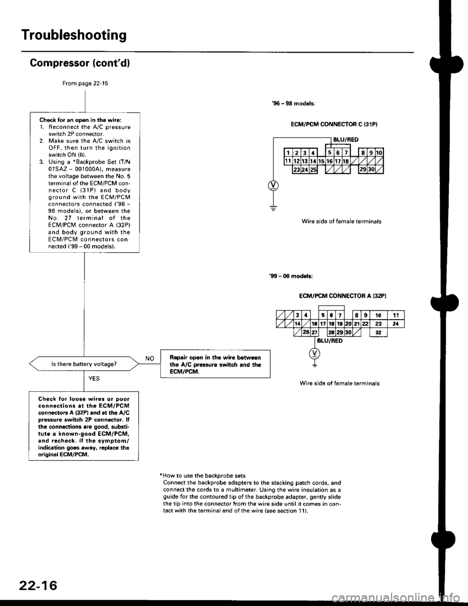
'96 -98 models:
ECM/PCM CONNECTOR C 13lPI
Wire side ot female terminals
'9!t - 00 mod.bi
ECM/PCM CONNECTOR A I32P)
Wire side ot female terminals
*How to use the backprobe setsConnect the backprobe adapters to the stacking patch cords, andconnect the cords to a multimeter. Using the wire insulation as aguide for the contoured tip of the backprobe adapter, gently slidethe tip into the connector from the wire side until it comes in con-tact with the terminal end ofthe wire {see section 11}.
From page 22-15
Check for an open in thg wire:'1. Reconnect the A"/C pressure
switch 2P connector.2. Make sure the A/C switch isOFF, then turn the ignitionswitch ON (ll).
3. Using a *Backprobe Set {T/N07SAZ - 001000A), measurethe voltage between the No. 5terminal of the ECM/PCM con-nector C (31P) and bodyground with the EcM/PcMconnectors connected ('96 -
98 models), or between theNo. 27 terminal of theECM/PCM connector A (32P)
and body ground with theECM/PCM connectors connected ('99 - 00 models).
Rapdir open in tho wi?e botwaonthe A/C pr..-ruro lwitch rnd th.ECM/PCM.
Check lor loo3e wires or ooolconnections at the ECM/PCMconnectoB A l32P) and at the A/Cpressure switch 2P connector, lfthe connections are good, substi-tute a known-good ECM/PCM,and recheck. lf the svmptom/indication goos away, repbce theoriginal ECM/PCM.
31501E91011
tat6l11E1921222321
BLU/RED
22-16