2000 HONDA CIVIC Hazard switch
[x] Cancel search: Hazard switchPage 1300 of 2189
Dashboard
Gomponent Removal/lnstallation
(cont'd)
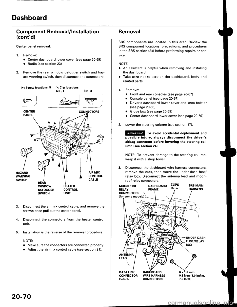
Center panel removal:
1. Remove:
. Center dashboard lower cover (see page 20-69)
. Radio {see section 23)
2. Remove the rear window defogger switch and haz-
ard warning switch, then disconnect the connectors.
>: Screw locations, 5 >: Clip locationsA>,4 B>,3
fii*-)
CENTERPANEI.
rt-xR.
W
IHAZARDWARNINGswlTcH
r44 "
F.IZvl
IIREARwtNoowOEFOGGERswtrcH
MtxCONTNOLCABLE
3. Disconnect the air mix control cable, and remove the
screws, then pull out the center panel.
4. Disconnect the connectors from the heater control
u nit.
5. Installation is the reverse of the removal procedure.
NOTE:
. Make sure the connectors are connected properly.
. Adjust the air mix control cable (see section 21).
20-70
Removal
SRS components are located in this area. Review the
SRS component locations, precautions, and procedures
in the SRS section (24) before preforming repairs or ser-
vice.
NOTE:
. An assistant is helpful when removing and installing
the dashboard.
. Take care not to scratch the dashboard, body and
related parts.
1. Remove:
o Front and rear consoles (see page 20-67)
. Console panel (see page 2O 67),
. Driver's dashboard lower cover and knee bolster(see page 20-68)
. Glove box (see page 20-69)
. Center dashboard lower cover (see page 20-69i
2. Lower the steering column (see section 17).
@ To avoid accidental deplovment and
possible injury, always disconnect the driver's
airbag connector belore lowering the steering col-
umn lsee section 241.
NOTE: To prevent damage to the steering column,
wrap it with a shop towel.
3. Disconnect the dashboard wire harness connectors,
remove the nuts, then move the under-dash fuse/
relay box. Disconnect the antenna lead and moon-
roof relay connectors.
DASHBOARD cltPs
CONNECTORS(for some models)
MOONROOFRELAY
ANTENNALEAO
FRAME
SRS MAINHARNESS
9.8 N.m (1.0 kgf m,7.2lbt.ltl
DATACONNECTOR WIRE HARNESSDetach. CONNECTORS
Page 1365 of 2189
DashboardBumpers
I
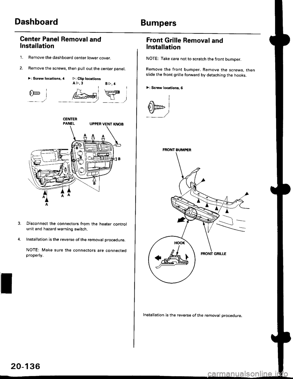
Center Panel Removal and
Installation
1. Remove the dashboard center lower cover.
2. Remove the screws, then pull out the center panel.
>: Sc.ew locationi,4 >: Clip locationsA >,3B>,4rl
@Y,
UPPER VENT I(NOB
Disconnect the connectors from the heater controlunit and hazard warning switch.
Installation is the reverse of the removal procedure.
NOTE: Make sure the connectors are connectedpropefly.
20-136
Installation is the reverse of the removal procedure.
FRONT BUMPER
a&
Front Grille Removal and
Installation
NOTE: Take care not to scratch the front bumper.
Remove the front bumper. Remove the screws. thenslide the front grille forward by detaching the hooks.
>: Scrow locltion3,6
I
dbp i
Page 1416 of 2189
Heater Control Panel
'95 - 98 modolsi
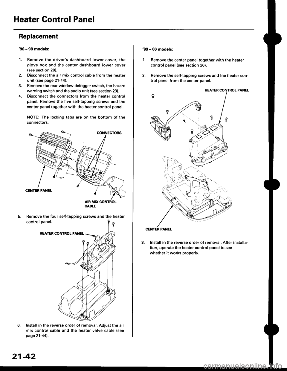
Remove the driver's dashboard lower cover, the
glove box and the center dashboard lower cover(see section 20).
Disconnect the air mix control cabls from the heater
unit {see page 21-44).
Remove the rear window defogger switch, the hazard
warning switch and the audio unit (see section 23).
Disconnect the connectors from the heater control
panel. Remove the five self-tapping screws and the
center panel together with the heater control panel.
NOTE: The locking tabs are on the bottom of the
connecrors.
Install in the .everse order of removal. Adjust the air
mix control cable and the heater valve cable {seepage 21-44)..
Replacement
1.
Remove the four self-tapping screws and the heater
21-42
1.
'9!, - 00 modols:
Remove the center panel together with the heater
control panel (see section 20).
Remove the self-tapping screws and the heater con-
trol panelfrom the center Danel.
Install in the reverse order of removal. After
tion, operate the heater control panel to see
whether it works properly.
installa-
Page 1471 of 2189

l'f .
Electrical
Special Toofs .,....................,23-2
Troubleshooting
Tips and Precautions ..............,.................... . 23-3
Five-step Troubleshooting .............. ......... . . 23-5
wire color codes ..........,23-5
Schematic Symbols ........,................... . . .. .... 23-6
Relay and Control Unit Locations
Engine Compartment ...,..................... ... .. . 23'7
Dashboard ......................23-8
Dashboard/Door ......... 23-12*Airbags ................. ....... Section 24
Air Conditioning ......... Section 21
Aftelnator ..........."""" """ 23-112
Anti-lock Brake System {ABS) Section 19*A/T Gear Position Indicator .....................,. .... ... 23-149
Automatic Transmission Svstem .... . ....... Section 14
Batterv ......... . . . ... ...... .......23-91
Blower controls .. . ... Section 2l
Charging System ....'...........23'112
Connector ldentilication and Wire Harness
Routing .................. ......23'13
Cruise Control ............,........23-240
Dash Lights Brightness Controller ............. ....... 23-180
Fan controfs "" 23'126
Fuel PumD ........ . ........ section 11
Fuses/Refay ...............,..,,.. 23'62
PGM-FI Control System ......................,....... Section 1 1
*Gauges
Circuit Diagram ....,.,.......23-131
Fuef Gauge ...........'.'.......23-142
Gauge/lndicator .. . .. 23-129
Ground Distribution .. . 23-75
Heatei controls .. . ..... Section 21*Horn................. ...............23-196
*tgnition Switch ....................23-89
lgnition System .......,.... 23-102
*lntegrated Control Unit ....................................... 23-156
fnterlock System ,........ . . , ,23-144
Lighting System . . . .. ......... 23-161
Lights, Exterior
Back-up Lights ..'............23'171
Brake Lights .................. 23'174
Daytime Bunning Lights (Canadal ............... 23'166
Front Parking Lights ......,................ .'. .......... 23-167
Front Turn Signal Lights .......... . . ............ ..,.23-167
Headtights ....".'....-... ..... 23'167
High Mount Brake Light ...................... ... .23'179
License Plate Lights ...... 23'176
Taitfights ................ .......23'171
lnterior Lights ..-.......,, . 23-142
Moonroof ..,.................,........ 23-235
Power Distribution ....... . . .23-61
Power Door Locks .......,,,. .23'251
Power Mirrors ,..............,.,...23'206
Power Relays ....... . ...... . . .. 23-86
Power Windows ............,,....23-220
Rear Window Defogger .......................... . . ... . . 23-2OO
Spark Plugs . ..... . ........ .....23-111
Slarting System ................23-93*stereo Sound Svstem ,................. ..... ... . ... ,.,.,,23'147'Supplemental Restraint System (SRS) ... . Section 24
Turn Signal/Hazard Flasher System .......'.'....-... 23-173
*Undel-dash Fuse/Relay Box ............,.................. 23-85
vehicfe soeed sensor (VSSI """" ""' 23-140+Wipers/Washers .........,.,.,...23-214
NOTE: Unless otherwise specified, references to auto-
matic transmission (Mf) in this section include the CVT.
Page 1509 of 2189
D
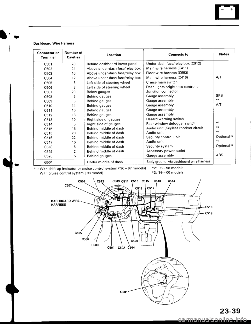
Dashboard Wire Harness
Connector ol
Terminal
Numbel of
CavitiesLocationConnects toNotes
c501
c502
c503
c504
c505
c507
c508
c509
c510
c513
c514
c515
c516
c518
c519
c520
20
24
to
12
5
3
20
5
5
14
r0
5
20
22
5
2
5
Behind dashboard lower panel
Above under-dash luse/relay box
Above under dash Iuse/relay box
Above under dash tuse/relay box
Left side of steering wheel
Left side of steering wheel
Below gauges
Behind gauges
Behind gauges
Behind gauges
Behind gauges
Behind gauges
Right side ot gauges
Right side oI gauges
Beh ind middle of dash
Behind middle of dash
Behind middle of dash
Behind middle of dash
Behind middle of dash
Behind middle of dash
Behind gauges
Under-dash {use/relay box (C912)
Main wire harness 1C411)
Floor wire harness (C553)
Main wire harness (C410)
Cruise main switch
Dash lights brightness controller
Junction connector
Gauge assembly
Gauge assembly
Gauge assembly
Gauge assembly
Gauge assembly
Hazard warning switch
Rear window defogger switch
Audio unit (Keyless receiver circuit)
Audio unit
Security control unit
Audio unit
Security system
Accessory power outlet
Gauge assembly
A"r
SRS
A,/r
Optio nal*'�
Option al*'�
ABS
G501Under middle ol dashBody ground, via dashboard wire harness
*1: With shiit-up indicator or cruise control system ('96 - 97 models)
With cruise control system ('98 model)
c509 C511 c510 c515
13 lc5l7
*2: '96 98 models*3: '99 - 00 models
c508
DASHSOARD WIREHARNESS
c501
c520
c502 c504
23-39
Page 1533 of 2189
(l'-
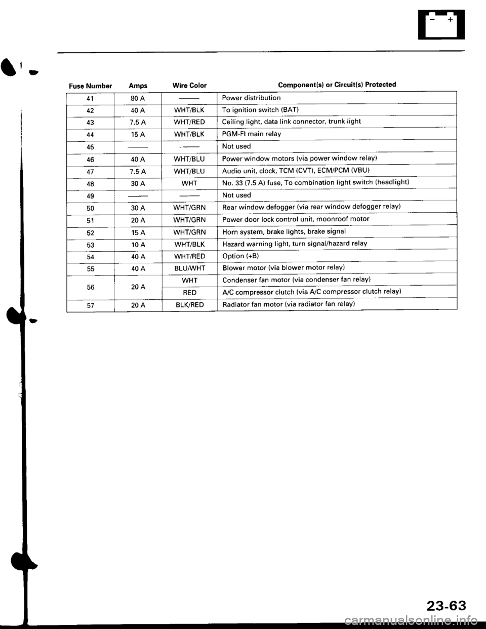
Fuse NumberAmpswire ColorComponent(s) or Circuitlsl Protect€d
4180APower distribution
4240AWHT/BLKTo ignition switch (BAT)
437.5 AWHT/REDCeiling light, data link connector, trunk light
4415 AWHT/BLKPGM-Fl main relay
Not used
4640AWHT/BLUPower window motors (via power window relay)
477.5 AWHT/BLUAudio unit, clock, TCM (CVT), ECM/PCM (VBU)
4830AWHTNo.33 (7.5 A) fuse, To combination light switch (headlight)
49Not used
5030AWHT/GRNRear window defogger (via rear window defogger relay)
cl20AWHT/GRNPower door lock control unit, moonroof motor
15 AWHT/GRNHorn system, brake lights, brake signal
10 AWHT/BLKHazard warning light, turn signal/hazard rclay
54404WHT/REDOption {+B)
5540ABLU,A/VHTBlower motor (via blower motor relay)
204WHTCondenser fan motor (via condenser fan relay)
REDl'lc compressor clutch (via IVC compressor clutch relay)
204BLVBEDRadiator fan motor (via radiator fan relay)
23-6
Page 1535 of 2189
lr-
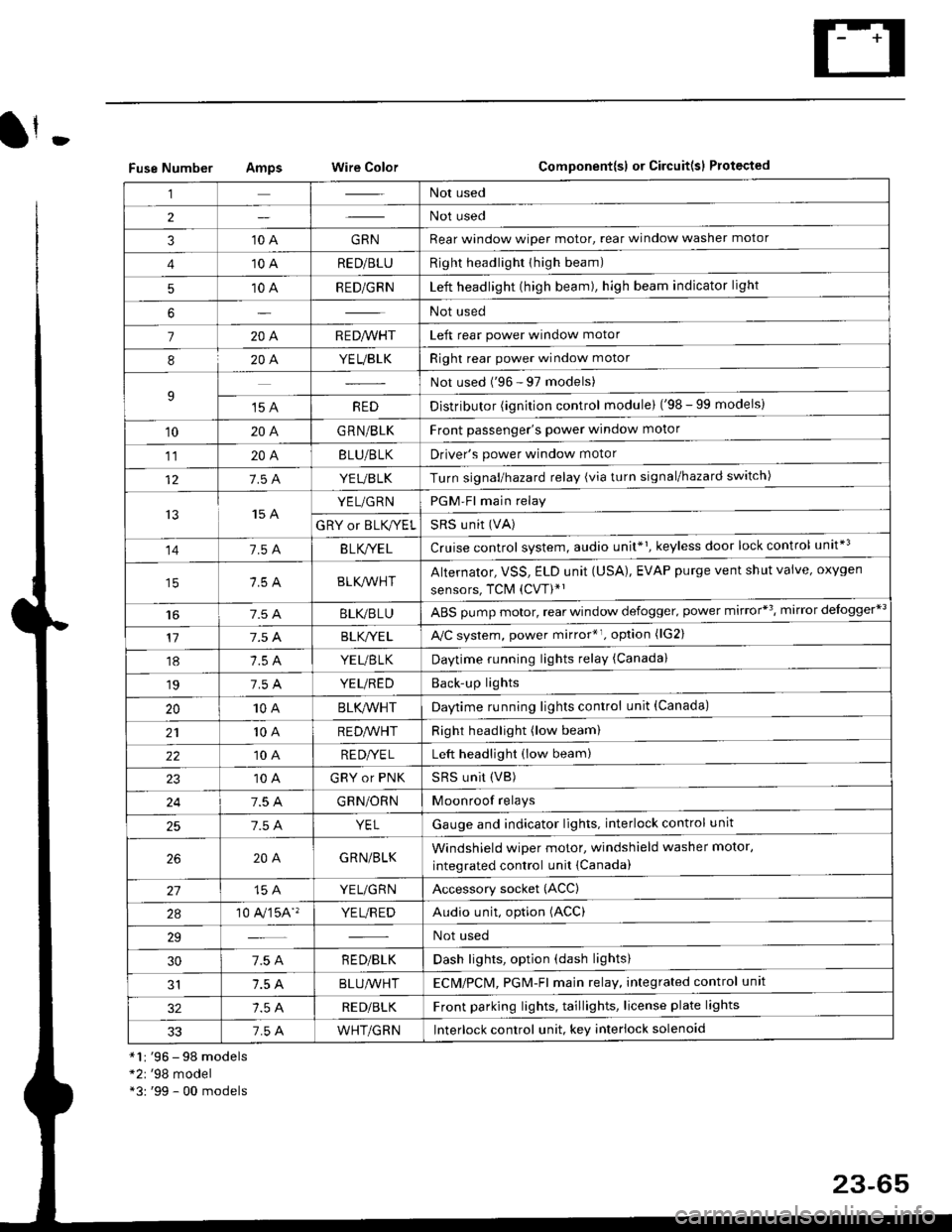
Fuse NumberAmpswire ColorComponent{sl or Circuit(sl Protected
*1r '96 - 98 models*2r '98 model*3: '99 - 00 models
,lNot used
2Not used
310 AGRNRear window wioer motor, rear window washer motor
410 ARED/BLURight headlighr thigh beam)
510 ARED/GRNLeft headlight (high beam), high beam indicator light
6Not used
7204R E D/VVHTLeft rear power window motor
820A.YEUBLKRight rear power window motor
9Not used ('96 - 97 models)
't5 AREDDistributor (ignition control module) ('98 - 99 models)
10204G RN/BLKFront passenger's power window motor
1120ABLU/BLKDriver's power window motor
127.5 AYEUBLKTurn signal/hazard relay (via turn signal/hazard switch)
t515 AYEL/GRNPGM-Fl main relay
GRY or BLK,^/ELSRS u nit (VA)
141.54B LK/YE LCruise control system, audio unit*1, keyless door lock control unit*3
BLK/lr'r'HTAlternator, VSS, ELD unit (USA), EVAP purge vent shut valve, oxygen
sensors, TCM (CVT)*'
t6BLI(,/BLUABS pump motor, rear window defogger. power mirror*3, mirror delogger*3
177.5 ABLK,/YE LA,/C system, power mirror*r. option (lG2)
18YEUBTKDaytime running lights relay (Canada)
197.5 AYEUREDBack'up lights
2010ABLK/VVHTDaytime running lights control unit (Canada)
2110 AREDA/VHTRight headlight (low beam)
2210 ARE DI/E LLeft headlight (low beam)
10 AGRY or PNKSRS UNit (VB)
247.5 AGRN/ORNMoonroof relays
257.5 AYELGauge and indicator lights. interlock control unit
204GRN/BLKWindshield wiper motor, windshield washer motor,
integrated control unit {Canada)
15 AYEL/GRNAccessory socket (ACC)
2a10 A,/'�]5A''YE L/R EDAudio unit, option (ACC)
29Not used
307.5 AR ED/BLKDash lights, option (dash lights)
1.5 ABLUA/VHTECM/PCl\4, PGM-Fl majn relay, integrated control unit
RED/BLKFront parking lights, taillights, license plate lights
337.5 AWHT/GRNlnterlock control unit. key interlock solenoid
23-65
Page 1539 of 2189
t
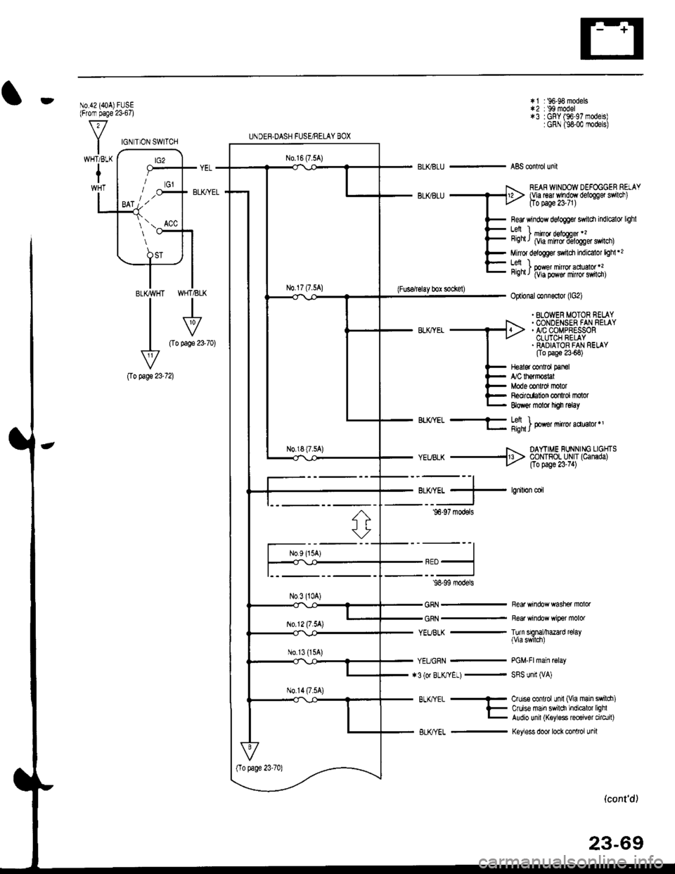
BLI(BLU - ABS controlunit
r 96'9€ models: 99 modol: GRY (96-97 models: GRN (9&00 models
Rear window d8loloer swilch indicalo. l€ht
::: ) mirroa d€loQor r?Hrgn, Ma miror i;logger sYritch)
Miror dolog06r $ tdr indicalor lighl'2
191 ) oo*e, ri,,o, "qraor',hEn, ivra pow mircr sMdr
odional conna.ior 1lG2)
*2*3
REAR WINDOW DEFOGGER RELAY{Via Gar wndow deloggot sw ch)fro page 23-71 )
N0.42 (40A)FUSE(Frofir page 23.67)
WHTi BLK
t
lFusdrelay bor socl(el)WHT/BLK
I
V
fro page 23'70)
Ipag6 23-0o
. BLOWER MOTOR FELAY. CONDETISER FAN RETAY. ,VC COMPRESSORCLWCH RELAY. NAONTOR FAN RELAY0o pag€ 2368)
12)Heal€r conlrol Pan6l,ryC her|lDshlMode conlrol molorReorolalion conlol molorAow€r molor iEh aelay
YEUBLK -
YEUGRN -
:rl l^r A k/YF l -
B./"|YEL - Ctr|s€ conlrcl Jn (Via main swildr)
l- C'uEe ma'4 swildr 'ndicalot lEhlL Audio unil (K€y oss rece'ver drol4)
BLKryEL - Kevless door tock conlroi unit
UNDER.DASH FUSE/RELAY BOX
N0.16 (7.5A)
(To page 23'70)
No.l2 (7.5A)
N0.13 (15A)
N0.14 (7.54)
IGN TION SWITCH
BA1 ;.'
1 '.._ ACC
q, (/vrr - |.fi II ::: I mrcr mircr aqua|ol'r
F DAY'IME FUNNING LIGHISvELrtsLK -113> CONTFOL UN|T (Ceneda)t'- (f o We 23-71)
,F1J- ,n*,"',
'96-97 mod6ls
""j
'98-99 models
GRN -
GRN _
Rear window washer molof
Rear window wiper molor
Turn srgnal/hazard relay(Viaswilch)
PGM-Flmain relay
SRS unii (VA)
(cont'd)
23-69