Page 935 of 2189

Electrical Troubleshooting ('96 - 98 Models)
Troubleshooting Flowchart - TMA and TMB Sigrrals (cont,d)
TCM CONNECTOR 8 {22P}
Wire side of female terminals
PNK
PNK
PNK
from page 14 257
Check TMB Wire Continuity:1. Turn the ignirion switch OFF.2. Disconnect the C (31P) connec,tor from the ECM, and the I(22P) connector from the TCM.3. Check for continuity betweenthe 86 terminal ol the TCMand the C30 terminal of theECM,
Repair open in the wire betwe€nrhe TcM and the EcM.
Check TMB Wire tor a Short Cir-cuit:Check for continuity between the86 terminal ot the TCM or theC30 terminal ot the ECM andbody ground.
ls there continuity?
Check the TCM:1. Reconnect the B (22p) con-nector to the TCM, and the C(31P) connector to the ECM.2. Turn the ignition switch ON (ll).3. Measure the voltage betweenthe B6 terminat of the TCMand body ground.
ls there approx. S V?
Check for loose TCM connoctors.lf necessary, substitute e lnown-good TCM and recheck.
o
2I67t8I10
12131416171820
ECM CONNECTOR C 131P}
2a5678I10
ll1213la17118
/l/l )/)/l/l )aol'ol/
PNK
o
2456,8910
1213111516111E20
2157810
1213141516171820
It
Page 939 of 2189

Electrical Troubleshooting ('96 - 98 Modelsl
Troubleshooting Flowchart - Pl Indicator Light Does Not Gome On
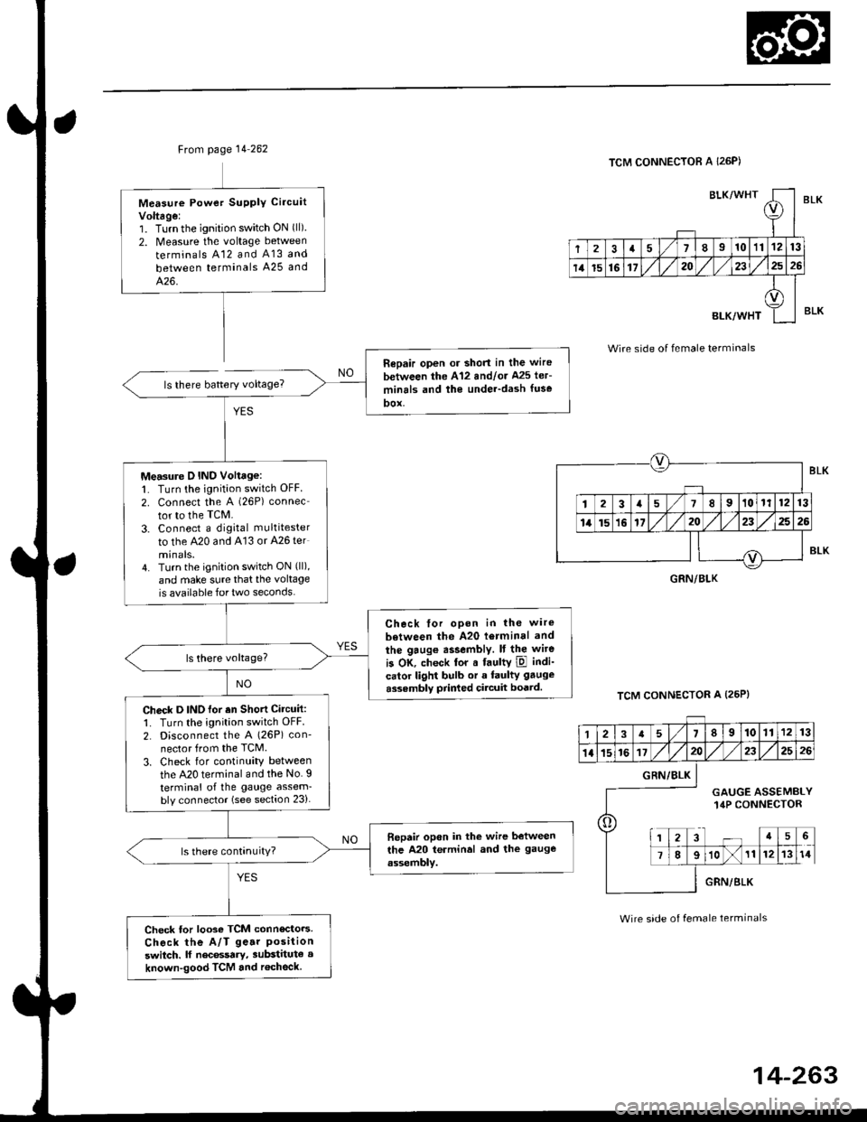
TCM CONNECTOR A {26P)
BLI
l-I
123a589101t12nl
1a151617202325rt
o
8LK
Wire side of female terminals
The E Indicator light does notcome on when the ignition switchis tirst turned ON {ll). {lt shouldcome on for aboul two s€conds,)
Chock the Service Check Connec-lot:Make sure the special tool (SCS
Service Connector) is not connected to the seryice check connector,
ls the special tool (SCS ServiceConnector) connected to the ser-vice check connector?
Disconn€ct the sDecial tool fromthe seruice check connector andrecheck.
Check the E Indicator Light:Shift to [5] oosition.
Check fo. loose TCM connectors.lf neceasary, substitute a known-good TCM .nd rochock.
Does the E indicator lightcome on?
Ch€ck th6 Ground Circuit:1. Turn the ignition switch OFF.2. Disconnect the A 126P) con-nector from the TCM.3. Check tor continuity betweenthe A13 terminal and bodyground and the 426 terminaland body ground.
.Repair open in the wiresbetwoon lhe A13 or A26 termi-nel3 and G101.. Repai. poor ground {G1011.
To page 14-263
14-262
>.
Page 940 of 2189

Ftom page 14 262
ls there battery voltage?
Measure Powet SUPPIY Ci.cuit
Voltage:1. Turnthe ignition switch ON (ll)
2. Measure the voltage between
terminals A12 and A13 and
between terminals A25 and
426.
Repair open or short in the wire
between the A'12 andlor Ms ler-
minrls and the under-dash fuse
DOX,
Measure D IND Voltage:1. Turn the ignition switch OFF
2. connect the A (26P) connec
tor to the TcM.
3. Connect a digkal multitester
to the A20 and A'13 or A26 ter
minals.4. Turn the ignition switch ON (ll),
and make sure that the voltage
is available for two seconds.
Check tor opon in the wire
between the A20 l6rminal and
the gaug€ assembly. It the wite
is OK, check tor a faultY ipl indi-
calor light bulb or a faulty gauge
assembly prir ed circuit boatd.
Check D INO for an Shott Circuit:1. Turn the ignition switch OFF
2. Disconnect the A (26P) con-
nector from the TCM.
3. Check for continuity between
the A20 terminal and the No. I
terminal of the gauge assem-bly connector (see section 23).
Bepair open in the wire between
the A20 terminal and the gauge
assembly.
Check tor looso TCM connecto.s.
Check the A/T ge.r Positionswitch. lf nec6ssary, substitute a
known-good TCM and r€check
BLK/WHTI
r
2a710111213
14t5161720232526
BLK/WHT
A
II
TCM CONNECTOR A I26P)
Wire side of female terminals
TCM CONNECTOR A (25P}
BLK
BLK
GRN/BLK
12a58910111213
1l15161720232526
o
GRN/BLK
GAUGE ASSEMBLY14P CONNECTOR
a5
78910111214
GRN/BLK
Wire side of female terminals
Page 945 of 2189

Electrical Troubleshooting {'99 - 00 Models)
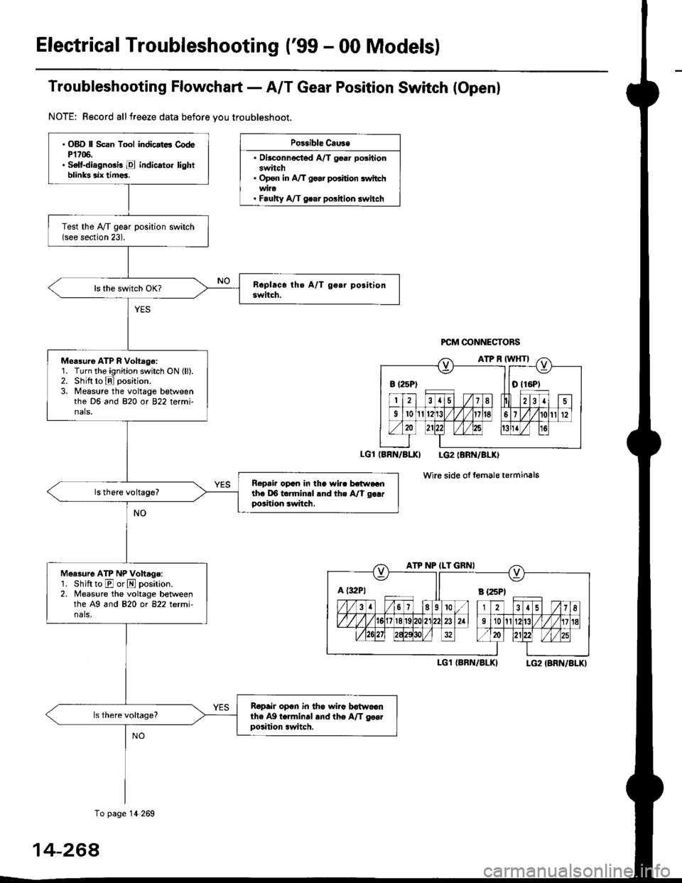
Troubfeshooting Flowchaft- AIT Gear Position Switch (Openl
NOTE: Record allfreeze data before vou troubleshoot.
Po$ible Cau3e
. Oilconnected A/T goar positionswitch. Op€n in A/T go.r po.ition switchwi?o. Faulty A/T gear polition switch
PCM @NNECTORS
(BRN/BI.XI LG2IBRN/BLKI
wire side of fomale terminals
I-G1 (BRN/BLKILG2 {BRN/BLK)
B {25P) I tO (16P1
ATP NP ILT GRNI
A t:r2Pt Il s tzspt
. OBD ll Scan Tool indicstE CodeP1706.. Selt-diagnGi! E indicato. lightblinks six tim€a.
Test the IVT gear position switch(see section 23).
Measu.e ATP R Voltage:1. Turn the ignition switch ON (ll).2. Shift to E position.
3. Measure the voltage betweenthe D6 and 820 or 822 termi-nals,
Ropair opcn in the wi.. hr.raGnth6 DO torminrl lnd the A/t g..rposition awitch.
Measure ATP NP Vohage:'1. Shift to E or N position.2. Measure the voltage betweenthe A9 and 820 ot 822 letmi-nals,
Ropair op6n in th€ wiro b€{woanthe Ag t.rminal and the A/T go..position .witch.
To page 14 269
14-264
Page 946 of 2189
From page 14-268
LGl IBRN/BLK}
Moasule ATP D voltago:1. Shift to El position.
2. Measure the voltage between
the A7 and 820 or 822 termi
nals.
Repair open in the wira betwo6nthe A7 torminal and the A/T ge.rpo3ition switch.
Measure ATP S Vollag6:'1. Shiftto E position.
2. Measure the voltage betweenthe D13 and 820 or B22 terminals.
Repair op€n in tho wire betweenihe D13 terminal .nd the A/Tgear position switch,
A {32P} ll B l25Pl
LGl IBRN/BLK) LG2 (BRN/BLKI
(cont'd)
14-269
To page 14-270
Page 947 of 2189
Electrical Troubleshooting {'99 - 00 Models}
Troubleshooting Flowchart - A/T Gear Position Switch (Openl (cont'dl
Bepair opon in the wiro bgtw€enlho A22 torminal and the A/Tgoar poihion lwitch.
PCM CONNECTORS
B (25P1
LGT (BFN/ALK}
PCM CONNECTOR B I25PI
12.15 / 7I
9't0l1Br1/l/41it8
ll lLG2
o) (o)
IBRN/BLKI
Wire side of female terminals
From page 14-8-269
Msasuro ATP L Voftage:1. Shiftto E position.
2. Measure the voltage betweenthe A22 and 820 or 822 termi-nals,
Check LG Wiro for .n Open Cir-cuit:']� Turn the ignition switch OFF.2. Check lor continuity betweenthe 820 t€rminal and bodyground, and between the 822terminal and body ground.
Ropai' op.n in the wir€a botw.€nthe 820 rnd 822 toJminals .ndbody ground, and .opsi. poolground (Gl01l.
Check tor loose te.minal frt in th6PCM conn€ctors, lf n€cessary, sub-stitut€ a knowo-good PCM anda6check,
Wire side of female terminals
14-270
Page 948 of 2189

JTroubleshooting Flowchart - Shift Control Linear Solenoid
NOTE: Record all freeze data before you troubleshoot
Possiblc Cause
. Disconn€cted solenoid harnos3
connectol. Short or oDen in shilt controllinetr solonoid wiro. Faulty shift control linear sole_
noid. Op€n in VB SOL wite. ODen in PG'l and PG2 wires or
poor ground {G10'l)
f,
wire side ot female terminals
LG1 IBRN/BLKILG2IBRN/BLK)
{cont'd)
14-271
PCM CONNECTORS
B(25P) - Dll6P)
.OBD ll Scan Tool indicatos
Code P1870.. Solf-diagnosis E indic.lor light
indic.t€s Code 30.
M6a3ure VB SOL voltage:1. Turn the ignition switch OFF.
2. Disconnect the B 125P) and D(16P) connectors from the
PCM,3. Turn the ignition switch ON (ll).
4. Measure the voltage between
the D5 and 820 or 822 terminals.
Repair open or shod in the wire
between the D5 terminal and the
under-dash tuso/telay box.
Check the Ground Circuitl1. Turn the ignition switch OFF.2. Check lor continuity between
the terminafs 82 and 822 and
between terminals 810 and
820.
Repair open in the wi.e betwoen
the termin.ls 82, B10, B20, and
822 and G101. Repair Poolground (G101).
LG1 IBRN/BLKI
PCM CONNECTOR B PsPI
PG,I IBLK)
10 page 14-272
a
Page 950 of 2189

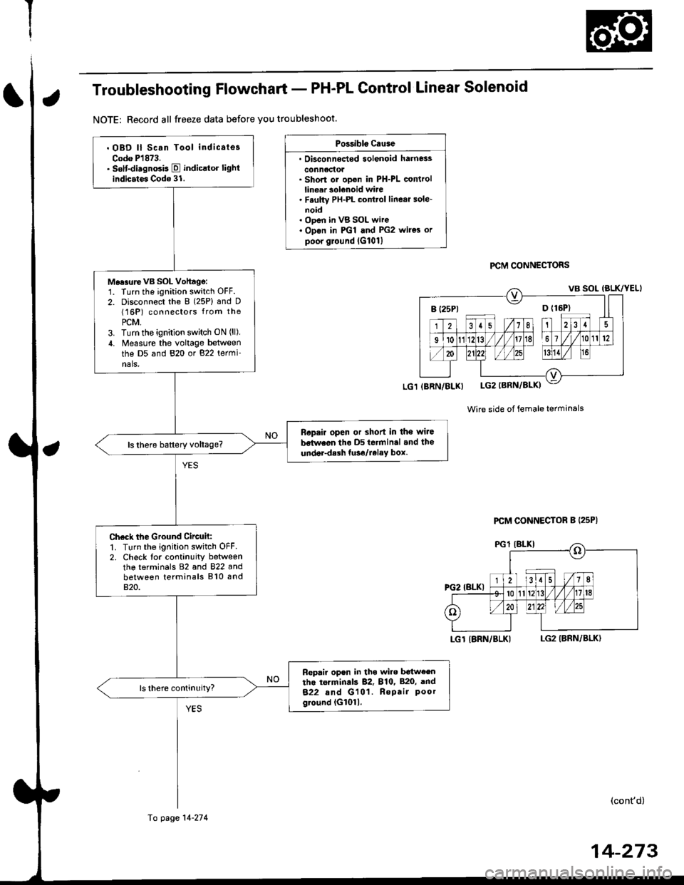
Troubleshooting Flowchart - PH-PL Control Linear Solenoid
NOTE: Record all freeze data before you troubleshoot.
Possibls c.use
. Oisconn6dod solenoid harness
conn6ctol. Short or ooen in PH-PL controllinear solenoid wire. F.ulty PH-PL cont.ol linear sole-noid. ODen in VB SOL wire. Op€n in PGl and PG2 wires orpoor ground lG101l
PCM CONNECTORS
Wire side of female terminals
LGT IBRN/BLKILG2 IBRN/BLK)
(cont'd)
B (25P1 D {16P}
. OBD ll Scan Tool indicates
Codo P1873.. sslt-disgnosis E indicltor lightindicates Code 31.
Mo.surevB SOL Vohagg:1. Turn the ignition switch OFF.
2. Disconnect the 8 (25P) and D(16P) connectors from the
PCM,3. Turn tho ignition switch ON (ll),
4. Measure the voltage between
the D5 and 820 or 822 termi-nals,
Ropair open or shod in the wiJe
bstwaon tho D5 terminal and the
under-dalh tuso/relay box.
Check the Ground Circuh:1. Turn the ignition switch OFF2. Check tor continuity betweenthe terminals 82 and 822 andbetween terminals 810 and820.
Fepair open in tho wiro b€tw€entho torminds 82, 810, 820, and
822 and G101. Repair Poorground (G1011.
(BRN/BLX)
Fo page 14-274
PCM CONNECTOR B (25P|
14-273