Page 775 of 2189

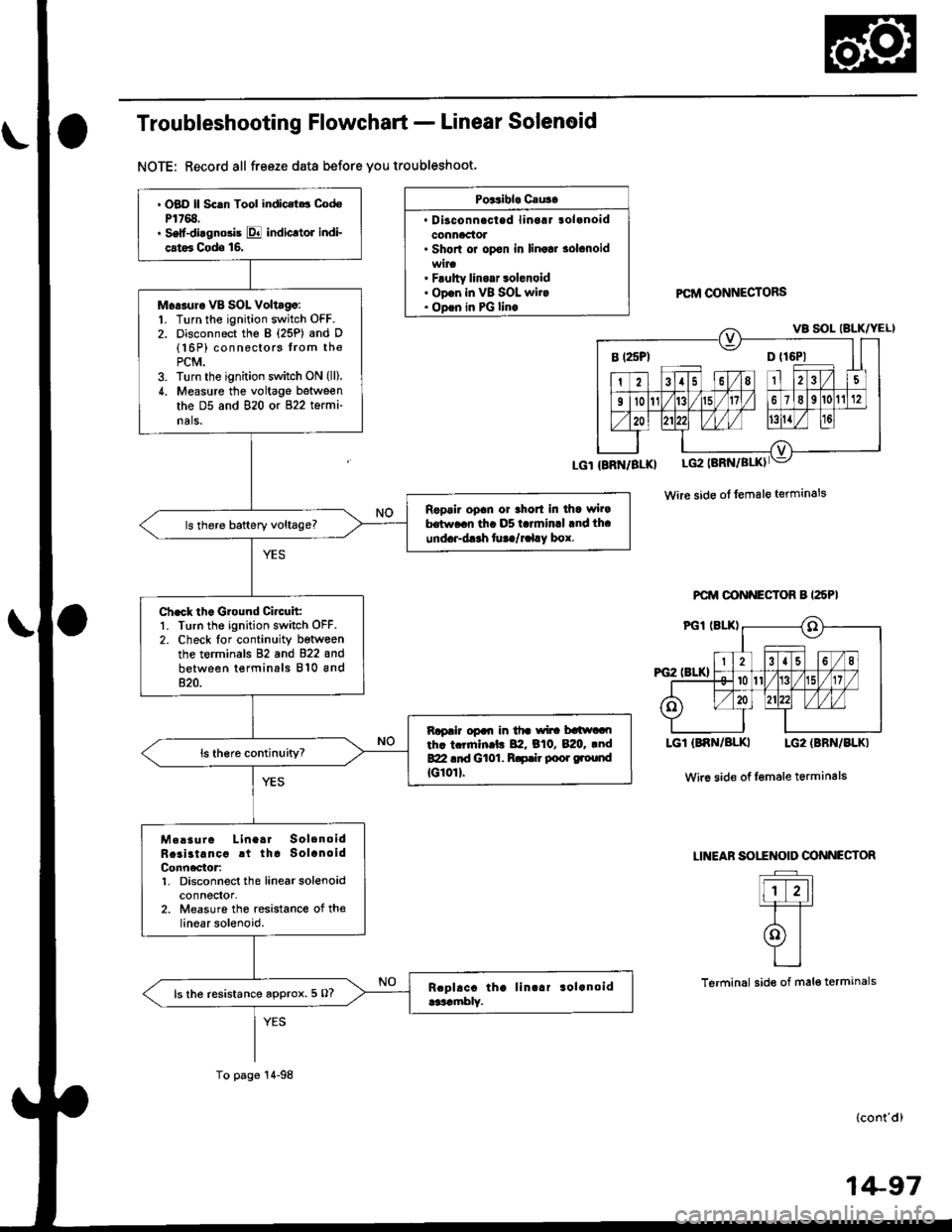
Troubleshooting Flowchart - Linear Solenoid
NOTE: Record all freeze data before you troubleshoot.
Poitibl. Cau3.
. Disconnacted linoaJ tolanoidconnaclol. Shorl or opon in linolr solonoid
. Flulty linoar 3olenoid. ODon in VB SOL wit.. ODen in PG linoPCftI @NNECTORS
Wire side ol female terminals
PCM OONNECTOR B I25PI
LGT (BNN/BLKI LG2 {BBN/BLKI
Wir6 side of Iemale terminals
LINEAF SOITNOID OONNECTOR
Flr-11=T=T
olYI
L_l
Terminal side of mal€ termanals
(cont'd)
B t25Pl D {16P1
. OBD ll Scln Tool indic.t.t CodoP1768.. Self-diagnosis E indicltol indi-
cat6 Cods 16.
Moasur. VB SOL Voltago:1. Turn the ignition switch OFF.2. Disconnect the B {25P) and D(16P) connectors from thePCM.3. Turn the ignition switch ON (lll.
4. Measure the voltage between
the D5 and 820 or 822 termi-
nals.
Ropair opan or thort in dla wi.9hrw..n th. D5 t.rminrl .nd th.
und.r-d.rh fu ta/r.l.y box.
Ch.ck th. Ground Circuit:1. Turn the ignition switch OFF.2. Check lor continuity betwoenthe terminals 82 and 822 and
between terminals 810 and820.
Rapair opal| in tfr wi|! batlwaoth. tcrrnln.l. 82, B10, B:20. .ndBZI .id Gt01. R.p.ir poor ground
tG10rl.
M.!sure Linea. SolenoidRcai3tancc rt tha SolanoidConn6ctor:1. Disconnect the linearsolenoidconnectol,2. Measure the resistance of thelinear solenoid.
ls the resistance approx. 5 O?
To page 14-98
1+97
Page 776 of 2189
Electrical Troubleshooting ('99 - 00 Modelsl
Troubleshooting Flowchart - Linear Solenoid (cont'dl
Check Linea. Solenoid tor aShort Ci.cuit:Check for continuity between thebody ground and the 88 terminaland B17 terminal individually.
PCM CONNECTOR A {25PI
Wire side of female terminals
From page 14 97
Repair shon in the wir6 betweenth€ 88 and 817 terminals and thelin€ar solenoid,
Measure Linear SolenoidResistance:1. Connect the linear solenoidconnector,2. Meas u re the resistancebetween the Bg and 817 termtnals,
Repair loose te.minal or open inthe wire botwoen the 88 .nd Bl7t.rmin.b end the linoar 3olenoid.
ls the resistance approx. 5.0 O?
Check for loose terminal tit in thePCM conn€ctors, lf necessary,substitut6 a known-good PCMand recheck.
LSAM (WHTI
14-98
Page 777 of 2189

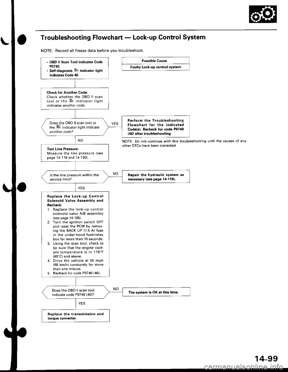
Troubleshooting Flowchart - Lock-up Control System
NOTE: Record all freeze data before vou troubleshoot.
Possibl€ Cause
Faulty Lock-up control sy3tem
NOTE: Do not continue with this troubleshootingother DTCS have been corrected.until the causes of any
OBD ll Scan Tool indicates Codem14/J.S€lf-diagnosis .D4l indicalor lightindicates Code 40.
Check for Another Code:Check whether the OBD ll scantool or the :E indicator lightindicates another code,
Perform the TroubleshootingFlowchart tor the indicatedCodels|. Rocheck to. code P0740(40) .fter troublBhooting.
ooes the OBD ll scan tool orrhe E indicator light indicateanother code?
Test Line Pressure:Measure the line pressure (see
page 14 119 and 14-120).
Repair the hydrrulic sy3tem asn6c6ssary (see page 14-1191.ls the lane pressure within theservice limit?
Replace the Lock-up ControlSolenoid Valve Assembly andRecheck:1. Replace the lock-up controlsolenoid valve A/B assembly(see page 14-105).2. Turn the ignition switch OFFand reset the PCM by removing the EACK UP (7.5 A) fusein the underhood {use/relaybox for more than 10 seconds.3. Using the scan tool, check tobe sure that the engine cool-ant temperature is in 176'F(80'C) and above.4. Drive the vehicle at 55 mph(88 km/h) constantly for morethan one minute,5. Recheck for code P0740 {40).
Does the OBD ll scan toolindicate code P0740 (40)?The svstem i3 OK .t this time.
14-99
Page 780 of 2189

Electrical Troubleshooting ('99 - 00 Models)
Troubleshooting Flowchart - E Indicator Light Does Not Come On
FCM CONNECTOR B (25P}
LGl {8RN/ALKI{BRN/8LK}
Wire side ol temale terminals
LGl IBNN/BLK} LG2 {BRN/BLK)
i2t5 6q
910t7
LG2
o) (o
The Pll indicator light does notcome on when the ignitionswitch is fi.st turned ON (ll). lltshould come on for about twoseconda.l
Check the Service Check Con-nector:Make sure the special tool (SCS
Service Connector) is not connect-ed to the service check connector?
ls the specialtool {SCS ServiceConnector) is not connected tothe seNice check connector.
Disconnect the special tool fromthe service check connector andr6check.
Check the Dll lndicator LightiShift to d position.
Check for loose terminal fit in thePCM connecto13. It necessary.sub3titute a known-good PCMand recheck.
Does the @ indicator lightcome on?
Check the Ground Circuit:1. Turn the ignition switch OFF.2. Disconnect the B (25P) con-nector from the PCM.3. Check for continuity betweenthe 820 terminal and bodyground, and between the 822terminal and body ground.
Repair open in the wiresbetween the B20 rnd 822 termi-nals and ground (G101), andrep.ir poor ground (G1011.
Measure Power Supply CircuitVoltage:1. Turn the ignition switch ON {ll}.2. Measure the voltage betweenterminals B1 and 822 andbetween terminals Bg and820.
Repair open or short in the wi.obetween th6 81 and/or 89 termi-nals and the PGM-FI main relav,and between th€ PGM-FI mainr€ley rnd the under-hood tus€/relay box.
To page 14''103
14-102
Page 782 of 2189
ElectricalTroubleshooting ('99 - 00 Modelsl
Troubleshooting Flowchart - Brake Switch Signal
PCM CONNECTORS
Wire side of female terminals
Shift lever cannot be moved tromE position with tho b.ake pedaldepressod.
Check Brake Light Operation:Depress the brake pedal.
Repair t ulty brake switch circuit{see s€ction 23}.Are the brake llghts ON?
Mea3ure STOP SW Vohage:1. Turn the ignition switch OFF.2. Disconnect the A (32P) and B{25P} connectors from thePCM,3. Measure the voltage betweenthe A32 and 820 or 822 termi-nals with the brake pedal
depressed.
Repair open in the wire betwsenthe A32 terminal rnd tho brrk6switch.
ls there battery voltage?
. Brak€ switch sign.l is OK.. Check for loose terminal fil inlhe PCM conn€ctors. lf neces-sary. substitute a known-goodPICM and recheck.. InsDect the breke 3witch circuitlsee section 231.
B {25P)
\
14-104
Page 789 of 2189
The following symptoms can be caused
by improper repair or assembly
Check these items,on th€^ ltems on thePROBABLE CAUSE DUE TO NOTES ListIMPROPER REPAIR List
Vehicle creeps in N position.R1, R2
Vehicle does not move in &l or Pll position.R4
Transmission locks up in E position.R3, R11
Excessive drag in transmission.R6K,R
Excessive vibration, rpm related.R7
Noise with wheels moving onlY.R5
Main seal pops out.R8
Various shifting problems.R9, RlO
PROBABLE CAUSE DUE TO IMPROPER REPAIR
lmproper clutch clearance.
lmproper gear clearance.
Park lever installed upside down.
one-way {sprag) clutch installed upside down.
Reverse selector hub installed upside down.
ATF pump binding.
Torque converter not fully seated in ATF pump.
Main seal improperly installed.
Springs improperly installed.
Valves improperly installed.
Shift fork bolt not installed.
14-11
Page 800 of 2189
Transmission
Removal
@Maks sure lifts, iacks and safety stands are placedproperly, and hoist bracket ate aftached to the cor_rec{ position on the engine lsee section 1).Apply parking brake and block rear whoels so vehiclewill not roll off stands and fall on you while workingunder it.
CAUTION: Use tender covers to avoid damaging paint-ed surfaces.
1, Disconnect the battery negative (_) terminal fromthe battery, then remove the positive (+) terminal.
2. Remove the intake air duct.
D16Y7 engins:
Remove the intake air duct and resonator.
D16Y8 engine:
Remove the intake air duct and the air cleaner hous-ing assembly,
3. Remove the starter cables and cable holder fromthe starter motor.
MOTOR CABLE
MOTOR CABLE
14-122
4. Remove the transmission ground cable, and discon_nect the lock-up control solenoid connector.
LOCK.UP CONTROLSOLENOID CONNECTOR
5, Disconnect the vehicle speed sensor (VSS) connec_tor and the countershaft speed sensor connector.
VEHICLE SPEED
Page 810 of 2189
End Cover
Removal
NOTE:
. Cleanall parts thoroughly in solvent or carburetor cleaner, and drywith compressed air,. Blow out all passages,
. When removing the right side cover, replace the following:- O-rings- Mainshaft and countershaft locknuts- Conical spring washgrs- End cover gasket
- Lock washer- Sealing washers
END COVER6 x 1.0 mm BOLT13 Bolts
PARK PAWL
PARK ITVER
LOCK WASHER
COUI{TERSI{AFTLINE AOLT
tST GEAF COLLAR
I
14-132
SEALING WASHERS