Page 815 of 2189

NOTE;
. Clean all parts thoroughly in solvent or carburetor
cleaner, and dry with compressed air.
. Blow out all passages.
. When removing the valve body, replace the O-ring.
l, Remove the ATF feed pipes from the servo body,
secondary valve body and main valve body.
For'96 - 98 models: Remove the ATF strainer and
servo detent base (two bolts).
For'99 - 00 models: Remove the ATF strainer (one
bolt).
Remove the servo body and servo separator plate
{'96 - 98 models: seven bolts,'99 - 00 models: eight
bolts).
Remove the secondary valve body, shaft stop and
secondary separator plate (three bolts).
Remove the lock-up valve body and separator plate
{seven bolts).
Remove the regulator valve body (one boltl.
Remove the stator shaft and stop shaft.
Remove the detent spring from the detent arm. then
remove the control shaft from the to.que converter
housing.
Remove the detent arm and detent arm shaft from
the main valve body.
Remove the main valve body (five bolts).
NOTE: Do not let the eight check balls fall outofthe
main valve body when removing the main valve
body.
Remove the ATF pump driven gear shaft, then remove
the ATF pump gears.
Remove the main separator plate and two dowel
pins.
7.
't'1.
10.
12.
14.
13. CIean the inlet opening of the ATF strainer thor-
oughly with compressed air. then check that it is in
good condition, and the inlet opening is not clogged.
INLET OPENING
Test the filter by pouring clean ATF fluid through
the inlet opening. Beplace the ATF strainer if it is
clogged or damaged.
NOTE: The ATF str8iner can be reused if it is not
clogged.
14-137
Page 820 of 2189
Main Valve Body
Disassembly/lnspection/Reassembly
NOTE:
. Cleanall parts thoroughly in solvent or carburetor cleaner, and drywith compressed air. Blowoutall passages.. Replace the valve body as an assembly if any pans are worn or damaged.. Check all valves for free movement. lf anyfail toslidefreely, see Valve Body Repairon page,l4-139.. Coat all parts with ATF during assembly.
CAUTION: Do not use a magnet to removs tha check balls; it may magnetizo the balls.
CPB VALVEVALVE CAP CLIP
ORIFICE CONTROL VALVE
BALLS, 8
lST ACCUMULATOR CHOKE
MODULATORVALVE
RELIEF VALVEVALVE
MAIN VALVE EODYInspect for wear, scratchesand scoring.
SEBVO CONTROL VAL
I.2 SHIFT VALVE
14-142
VALVE CAP
Page 822 of 2189

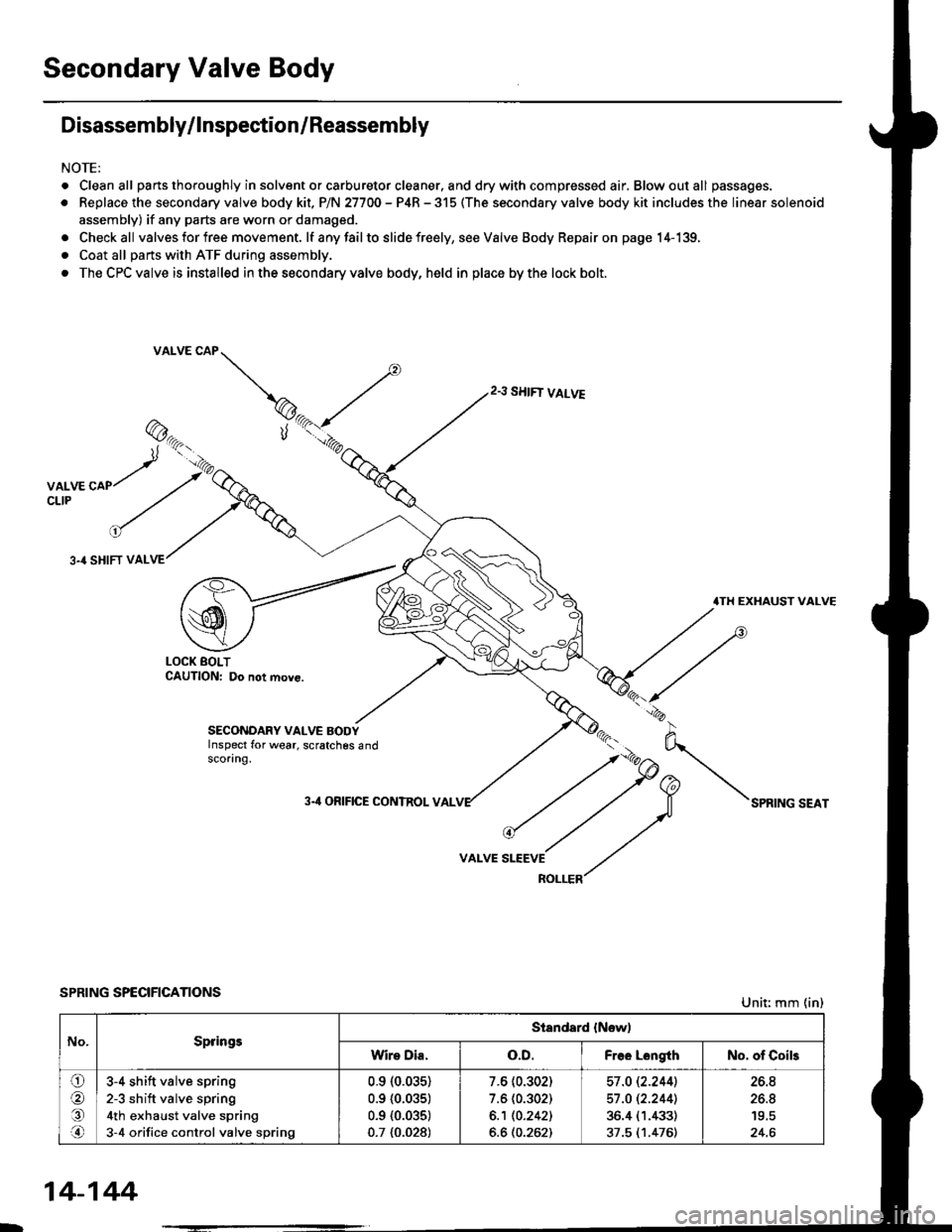
Secondary Valve Body
Disassembly/lnspection/Reassembly
NOTE:
. Cleanall parts thoroughly in solvent or carburetor cleaner. and drywith compressed air, Blowoutall passages.
. Replace the secondary valve body kit. P/N 27700 - P4R - 315 (The secondary valve body kit includes the linear solenoid
assembly) if any parts are worn or damaged.
. Checkall valves for free movement. lf anyfailto slide freely, seeValveBody Repairon page 14-139,
. Coat all parts with ATF during assembly.
. The CPC valve is installed in the secondary valve body, held in place by the lock bolt.
2.3 SHIFT VALVE
3.4 SHIFT VAL
.TH EXHAUST VALVE
LOCK BOLTCAUTION: Do not move.
SECONDARY VALVE BODYInspect for wear, scratches 6ndscoring.
3-'l ORIFICE CONTROL VAL
VALVE
SPRING SPECIFICATIONSUnit: mm (in)
No.SpringsStandard {New)
Wire Dia.o.D.Free LongthNo. of Coils
ora,.n
3-4 shift valve spring
2-3 sh ift valve spring
4th exhaust valve spring
3-4 orifice control valve spring
0.910.035)
0.9 {0.035)
0.9 {0.035)
0.7 {0.028)
7.6 (0.302)
7.6 (0.302)
6.1 10.2421
6.6 (0.262)
57 .O 12.2441
57 .O 12.2441
36.4 (1.433)
37.5 (1.476)
26.8
26.8
24.6
14-144
Page 823 of 2189

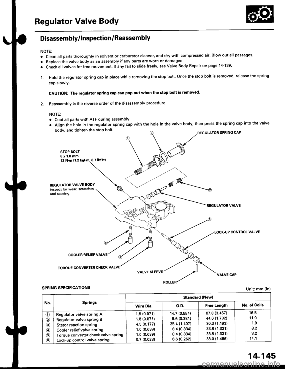
Regulator Valve Body
Disassembly/lnspection/Reassembly
NOTE:
. cleanall parts thoroughly in solvent or carburetor cleaner, and drywith compressed air. Blowoutall passages
. Replace the valve body as an assembly if any parts are worn or damaged.
. check allvalves for free movement. lf anyfail toslidetreely, see valve Body Repairon page 1+139.
1. Hold the regulator spring cap in place while removing the stop bolt. once the stop bolt is removed. release the spring
cap slowly.
CAUTION: The regulator 3pring cap can pop out when the stop boh is removod'
2. Reassembly is the reverse order ofths disassembly procedure.
NOTE:
o Coat all parts with ATF during assembly.
. Align the hole in the regulator spring cap with the hole in the valve body, then press the spring cap into the valve
body, and tighten the stop bolt.
STOP BOLT6x1.0mm12 N.m 11.28.7 tbf.lrl
^/^'ou*'oRsPRrNGcAP
*N@
REGULATOR VALVE
\=f -.-*
*fi /F { a-tLocK.uPcoNrRoLvALVE
cooLERRELlEFvALVr"r?
ry
roRouE coNvERrER cHEcKv ^LvE//
v ^r* "r**::f vi{LvE cAp
SPRING SPECIFICANONS
REGULATOR VALVE BODY
Inspect lor wear, scratches
and scorlng.
Unit: mm (in)
No,Springe
Standard (Now)
Wire Dia.o.D.Free LengrthNo. of Coils
o
o
@
@
@
Regulator valve sPring A
Regulator valve spring B
Stator reaction spring
Cooler relief valve spring
Torque converter check valve spring
Lock-up control valve sPring
1.8 {0.07'�r)
1.8 (0.071)
4.5 (0.177)
1.0 (0.039)
1.0 (0.039)
0.7 (0.028)
'r4.7 (0.584)
9.6 (0.381)
35.4 (1.407)
8.4 {0.334)
8.4 {0.334}
6.6 {0.262}
87.8 (3.457)
44.0 (1.732)
30.3 (1.193)
33.8 (1.331)
33.811.3311
38.0 {1.4961
11.0
1.9
8.2
a.2't 4.1
14-145
Page 825 of 2189
Lock-up Valve BodY
Disassembly/lnspection/Reassembly
NOTE:
. Clean all pans thoroughly in solvent or carburetor cleaner' and dry with compressed air' Blow out all passages'
a Replace the valve body as an assembly if any parts are worn or d€maged'
. Checkall valves for free movement ttanytaitio stlae freely' see Valve Body Repairon page 14-'139'
. Coat all parts with ATF during assembly
LOCK.UP VALVE BODY
Inspect for wear, scratchesand sconng.
VALVE CAP
LOCK-UP TIMING VAL
SPRING SPECIFICATIONSUnit: mm (in)
73.1 t2.902J
ao.7 13.'17717.6 (0.302)
8.1 (0.319)Lock-up shift valve sPrang
Lock-up timing valve sPrlng
14-147
Page 839 of 2189
CAUTION: lf eithd end of the 3pocial tool issotoveran
area ot the spring rstainer which is unsupport€d by tho
return spring, tho r€tain€l may be damagod. Bo eure the
special tool is adiusted to have full contact with tha
spring retainor.
SPRING RETAINER
4. Compfess the return sprang.
Do not sat horo.
5. Remove the snap ring. Then remove the special tools,
spring retainer and return spring.
Wrap a shop rag around the clutch drum, and apply
air pressure to the ATF passage to remove the pis-
ron.
Place a finger tip on the other end while applying
air pressure.
OSHA.APPROVED
SPRING RETAIItIER
PISTON
14-161
Page 863 of 2189

16. Install a new set ring on the end of each driveshaft'
17. Installthe right and left driveshafts (see ssction 16)
CAUTION: Whil6 installing the driveshafE in the
diffarential, be surs not lo allow du3t and othor for-
eign particl€s to enler into the transmission.
NOTE:
. Clean the areas where the driveshafts contact the
transmission (differential) thoroughly with sol-
vent or carburetor cleaner, and dry with com-
pressed air.
. Turn the right and left steering knuckle fully out-
ward, and slide each driveshaft into the differen-
tial until you feel its set ring clip engage the side
gear.
18. Install the damper fork, then install the rightand left
ball joints to the each lower arm with the castle nuts
and new cotter Plns.
DAMPER PINCH BOLT
10 x 1 .25 mma3 N.m l4.ia kgf.m,
32 tbl.ftl
4l
COTTERReplace.SELF.LOCKING NUT
12 x 1.25 mm
6il N.m t6.5 kgf'm, il7 lbf ftl
Replace.
19. Install the splash shield.
{5.0 - 6.0 kgf m, 36 - iB lbf'ft|
CASTLE NUT12 x 1,25 mm49 - 59 N.m
20. Connect the mainshaft speed sensor, the linear sole-
noid and the shift control solenoid connectors.
SHIFT CONTROL SOLENOIO LINEAR SOITNO|o
CONNECTOR CONNECTOR
6 r 1.0 mrn12 N.m (1.219f.m,
E.7 lbf.frl
CONNECTOR
21. Connect the countershaft speed sensor and the vehi-
cle speed sensor (VSS) connectors.
VEHICI..E SPEED
SENSOR CONNECTOR
COUNTERSHAFTSPEED SENSORCONNECTOR
(cont'dl
14-185
Page 864 of 2189

Transmission
Installation {cont'd)
Connect the lock-up control solenoid connector. andinstall the transmission ground cable.
6 x '1.0 mm12 N.m {1.2 kgf.m, 8.7 lbl.ft}
LOCK.UP CONTROLSOLENOID CONNECTOR
Connect the staner cables on the staner motor. andinstall the cable holder.
NOTE; When installing the starter cable terminal.make sure that the crimped side of the ring terminalis facing out (see section 23).
6x1.0mm12 N.m 11.2 kg{.m.8.7 tbtftl
{0.9 kg'f.m, 7 lbf.ftl
TRANSMISSIONGROUND CABLE
b
14-186
STARTER CAELE
24. Installthe intake air duct.
D16Y7 engine:
Install the intake air duct and the resonaror.
D16Y8 engine:
lnstall the intake air duct and the air cleaner hous_ang assembly.
25. Refill the transmission with ATF (see page 14_1.18).
26. Connect the positive (+) cable first. then the nega-tive (-) cable to the battery.
27. Check the ignition timing (see section 23).
28. Start the engine. Set the parking brake, and shift thetransmission through all gears. three times. Checkthe shift cable adjustment (see page 14_190).
29, Check the front wheel alignment (see section 1g).
30. Let the engine reach operating temperature (thecooling fan comes on) with the transmission in Nor @ position, then turn it off and check the fluidlevel (see page 14- 7).
31. Road test as described on pages 14-113 thru ,14_116.