Page 865 of 2189

Cooler Flushing
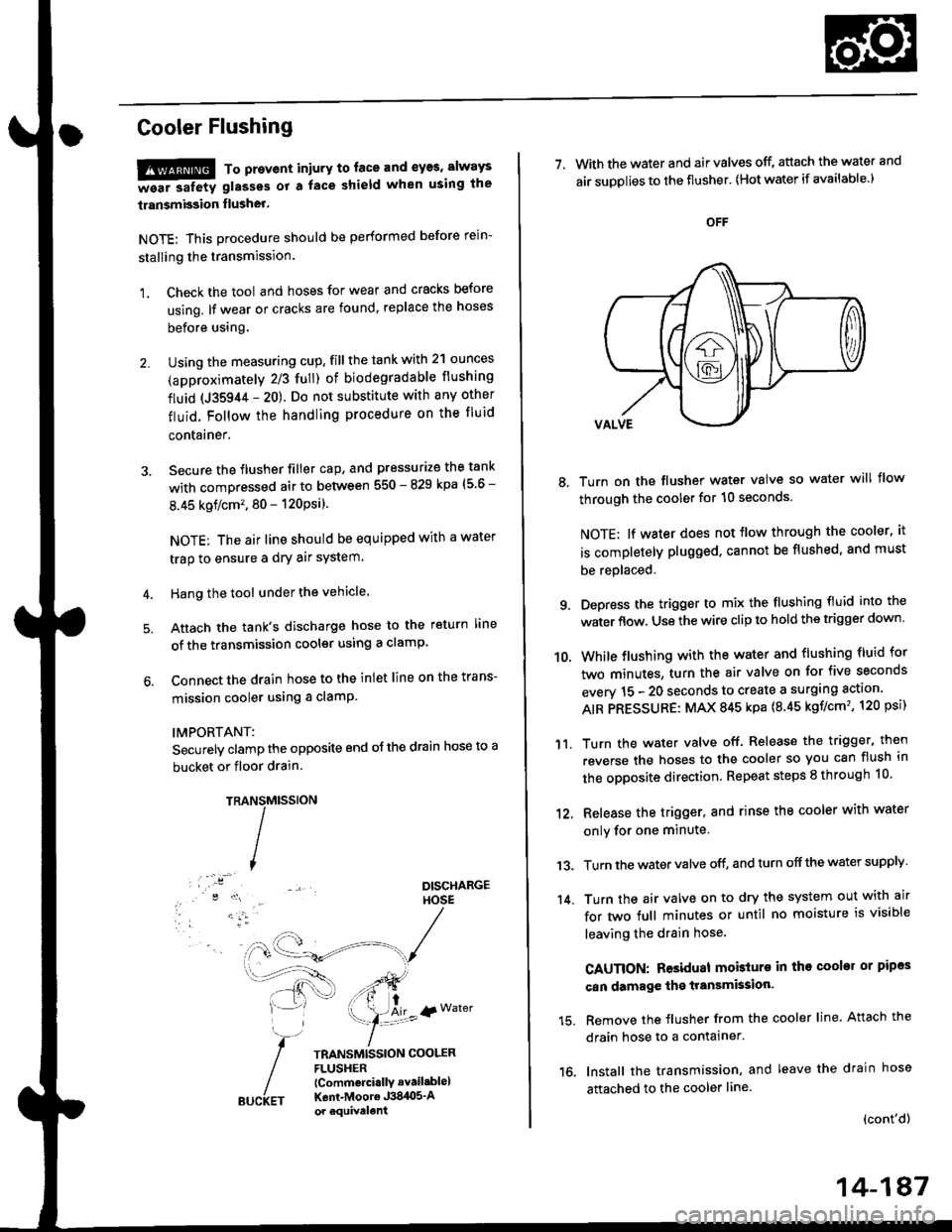
!!!@ To prevent iniury to. face and eyas, always
-ea. safetv glasses ot a face shield when using the
transmission flusher.
NOTE: This procedure should be performed before rein-
stalling the transmission.
1. Check the tool and hoses for wear and cracks before
using. lf wear or cracks are found, replace the hoses
before using.
Using the measuring cup, fill the tank with 2'l ounces
(approximately 2/3 full) of biodegradable flushing
fluid (J35944 - 20). Do not substitute with any other
fluid. Follow the handling procedure on the fluid
contarner.
Secure the flusher filler cap, and pressurize the tank
with compressed air to between 550 - 829 kpa (5 6 -
8.45 kgflcm'�. 80 - 120Psi).
NOTE: The air line should be equipped with a water
trap to ensure a dry air system.
Hang the tool under the vehicle.
Attach the tank's discharge hose to the return line
of the transmission cooler using a clamp.
Connect the drain hose to the inlet line on the trans-
mission cooler using a clamP
IMPORTANT:
Securely clamp the opposite end oJ the drain hose to a
bucket or floor drain.
TRAMtssroN
TRANSMISSION COOLERFLUSHER{Commcrci.llY avail.blel
Kent-Moore J384O5'Aor equivelent
NS
I
{r Water
7. With the water and air valves off, attach the water and
air suDolies to the flusher' lHot water if available.)
8, Turn on the flusher water valve so water will flow
through the cooler for 10 seconds.
NOTE; lf water does not tlow through the cooler, it
is completely plugged. cannot be flushed, and must
be replaced.
9. Depress the trigger to mix the flushing fluid into the
water flow. Use the wire clip to hold the trigger down'
While flushing with the water and flushing fluid for
two minutes, turn the air valve on for five seconds
everv 15 - 20 seconds to create a surging action'
AIR PRESSURE: MAX 845 kpa {8.45 kgf/cm'�, 120 psi)
Turn the water valve off. Release the trigger, then
reverse the hoses to the cooler so you can flush in
the opposite direction. Repeat steps 8 through 10'
12, Release the trigger, and rinse the cooler with water
onlv for one minute
13. Turn the water valve off, and turn off the water supply
14. Turn the air valve on to dry the system out with air
for two full minutes or until no moisture is visible
leaving the drain hose.
CAUTION: Residual mobturo in tho cooler or pipas
can damage the transmksion'
15. Remove the flusher from the cooler line. Attach the
drain hose to a contalner.
16. Install the transmission, and leave the drain hose
attached to the cooler line
{cont'd)
10.
'11.
14-187
Page 866 of 2189
Transmission
17.
Cooler Flushing (cont'dl
Make sure the transmission is in the E position.
Fill the transmission with ATF, and run the enginefor 30 seconds or until approximately 0.95 f (1.0 USqt.,0.8 lmp qt.) is discharged.
Remove the drain hose, and reconnect the coolerreturn hose to the transmission (see page l4-192).
Refill the transmission with ATF to the oroDer level(see page 14-118).
18.
19.
b
14-18A
TOOL MAINTENANCE
1. Empty and rinse after each use. Fill the can with waterand pressurize the can. Flush the discharge line toensure that the unit is clean.
2. lf discharge liquid does not foam, the orifice may beblocked.
3. To clean, disconnect the plumbing from the tank atthe large coupling nut.
ORIFICE
GRT{G
Remove the in-line filter from the discharge side andclean if necessary.
The fluid orifice is tocated behind the filter.Clean it with the pick stored in the bottom of thetank handle, or blow it clean with air. Securelvreassemble all Darts.
FILLER CAP
Page 911 of 2189

Troubleshooting Procedures
l. How To Begin Troubleshooting
When the E indicator light has been reported on, use the appropriate procedure below to diagnose and repatr theproDlem.
A. When the @ indicator light has come on:
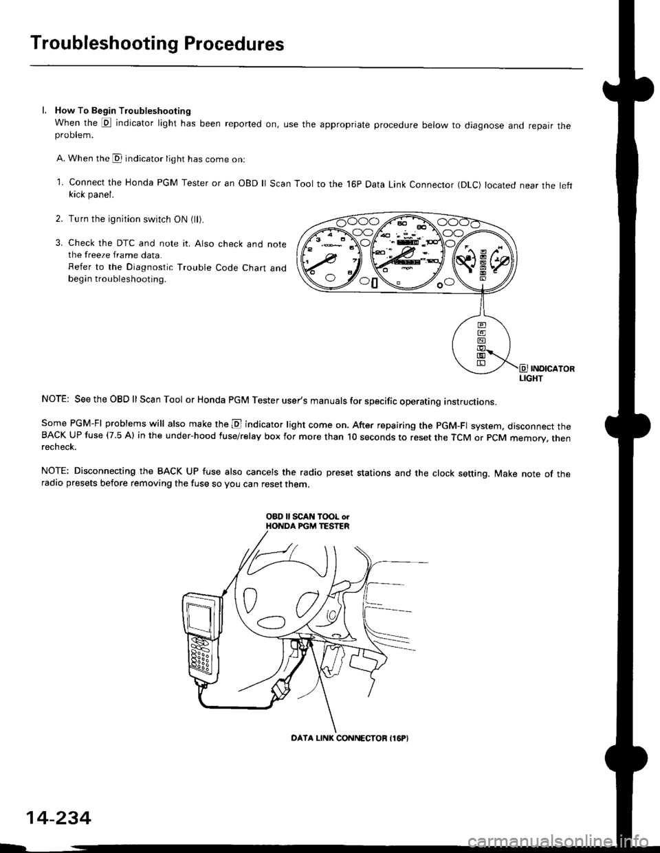
l connect the Honda PGM Tester or an oBD ll Scan Tool to the 16P Data Link Connector (DLc) located near the leftkick panel.
Turn the ignition switch ON (ll).
Check the DTC and note it. Also check and notethe freeze frame data.
Refer to the Diagnostic Trouble Code Chart andbegin troubleshooting.
INOICATORLIGHT
NOTE: SeetheOBDll Scan Tool or Honda PGM Tester user's manuals for specific operating instructions.
Some PGM-FI problems will also make the E indicator light come on. After repairing the pGM-Fl system, disconnect theBACK UP fuse (7.5 Al in the under-hood fuse/relay box for more than l0 seconds to reset the TCM or PCM memory, rnenrecheck.
NOTE: Disconnecting the BACK UP fuse also cancels the radio preset stations and the clock setting. Make note of theradio presets before removing the fuse so you can reset them,
2.
3.
o0\e--loo
OATA LINK CONNECTOB I16P}
14-234
Page 912 of 2189

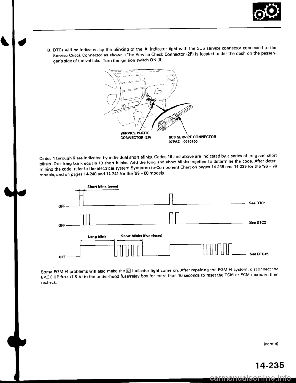
B. DTCS will be indicated by the blinking of the E indicator light with the SCS service connector connected to the
Service Check Connector as shown. (The Service Check Connector (2P) is located under the dash on the passen
ger's side of the vehicle.) Turn the ignition switch ON (ll).
CONNECTOR07PAZ - 00101(x)
codes 1 through 9 are indicated by individual shon btinks. codes 10 and above are indicated by a series of long and short
b|inks.one|ongblinkequa|sloshortb|inks.Addthe|ongandshortb|inkstogethertodeterminethecode.Afterdeter
miningthecode,refertothee|ectrica|systemsymptom-to-componentchartonpagesl4-238and14.239forthe,96_98
models, and on pages 14-240 and 14'241 for the '99 - 00 models
Soc DTCI
Sor DTC2
Long blinkShort blinks |tive tim€sl
some pGM-Ft problems wi
atso make the E indicator light come on. After repairing the PGM-FI system, disconnect the
BACKUPfuse(7.5A)intheUnder.hoodfuse/re|ayboxformorethanl0secondstoresettheTcMorPcMmemory,then
recheck.
Scc DTCI5
(cont'd)
14-235
iii:j
,,,/
CONNECTOR {2PI
Shorl blink (oncc)
Page 916 of 2189
lf the self-diagnostic E indicator light does not blink, perform an inspection according to the table below.
SymptomInspectionRef. page
E indicator light does not come on for two seconds after ignition switch
is first turn on (ll).14-262
E indicator light is on constantly (not blinking) whenever the ignition
switch is on (ll).14-264
NOTE:
. lf a customer described the symptom for code P1706 (6), it will be necessary to recreate the symptom by test driving,
then recheck the DTC.
. Sometime the E indicator light and the Malfunction Indicator lamp (MlL) may come on simultaneously. lf so, repair the
pGM-Fl system according to the DTc, then reset the memory by removing the BACK uP fuse in the under-hood
fuse/relay box for more than 10 seconds. Drive the vehicle for several minutes at a speed over 30 mph (50 km/h)' then
recheck the DTC.
14-239
Page 918 of 2189
lf the self-diagnostic E indicator light does not blink. perform an inspection according to the table below.
SYmPtom
IDI indicator light does not come on for two seconds after ignition switch
is first turned ON (ll).
lE1 indicator light is on constantly (not blinking) whenever the ignition
switch is ON { ll).
InspectionRef. page
14-284
14-290
NOTE:
. lf a customer described the symptom for code Pl706 (6), it will be necessary to recreate the symptom by test driving,
then recheck the DTC.
. iometimes, tfre E indicator light and the Malfunction Indicator lamp (MlL) may come on simultaneously lf so, repair
the PGM-Fl system accordrng to the DTC, then reset the memory by removing the BACK UP RADIO fuse in the under-
hood fuse/relay box for more than 10 seconds. Drive the car for several minutes at a speed over 30 mph {50 km/h)' then
recheck the DTC.
14-241
Page 919 of 2189

Electrical Troubleshooting ('96 - 98 Modelsl
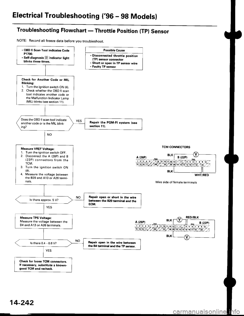
Troubleshooting Flowchart - Throttle position (Tpl Sensor
Possible Cause
. Disconnected throftle position(TPl 3ensor connoctol. Short or open in TP sensor wire. Fauhy TP sensol
TCM CONNECTORS
Wire s;de of female terminals
. OBO ll Scan Tool indic.tes CodeP1790.. Self-diagnosis E indicator lightblinks three times.
Check lor Anothar Code or MILBlinking:1. Turn the ignition switch ON 1 ).2. Check whether the OBD ll scantool indicates another code orthe Malfunction Indicator Lamp(MlL) blinks (see secrion 11).
Does the OBD ll scan tool indicateanothercode oristhe MIL blink-ing?
Repair the PGM-FI systom (3eesection 111.
Measure VREF Voltage:1. Turn the ignition switch OFF.2. Disconnect the A (26P) and B{22P} connectors lrom theTCM.3. Turn the ignition switch ON{fl).4. Measure the voltage bet\iveenthe 820 and A13 or 426 termi-nals,
Repair open or short in thc wireb,stween the Bao tcrminal rnd theECM.
ls lhere approx. 5 V?
Measure TPS Voltago:Measure the voltage between theB4 and A13 or 426 terminals.
Repail open in the wire tr€tweonthe Erl t6.minal ind the TP sen3o..ls there 0.4 - 0.6 V?
Check for loose TCM connectors.lf necessary, substitute a known-good TCM and r6check.
NOTE: Record all freeze data before you troubleshoot.
BLK
WHT/RED
A {26P1
Page 923 of 2189

Electrical Troubleshooting (,96 - 9g Models)
Troubleshooting Flowchart - A/T Gear position Switch (Openf
NOTE: Record all freeze data before you troubleshoot.
Pos.ribls Cause
. Disconnocted A/T gear positionswitch connector. Open in A/T gear position switch
. Faulty A/T gear position switch
TCM CONNECTOR A I26PI
Wire side of female terminals
. OBD ll Scan Toot indicat* CodeP1706,. Solf-diagnosis E indicator tightblinb six times.
Measule ATP R Volt.gei1. Turn the ignition switch ON l).2. Shifi to E position.3. Measure the voltage betweenthe A11 and 413 or ,426 termi-nals.
Repair open in tho wire betwoenlhe A11 terminal and the A/Tgoar po3ition switch.
Measure ATP NP Volt.gei1. Shifrto E orE position.2. Measure the voltage betlveenthe A10 and A13 or 426 terminals.
Repair open in the wiro betweenthe A10 terminal .nd tho A/Tgea. poshion swhch.
Measure ATP D Vohage:1. Shift to E position.2. Measure the voltage betweenthe Ag and A'13 or 426 termi-
Repair open in the wire lretweenthe A9 terminel and the A/T gearposition 3witch.
To page 14-Z4j
14-246