Page 96 of 2189

Engine RemovaUlnstallation
Removal
@@
1.
. Make sure iacks and salety stands are placed ploperly
and hoist brackets are attached to the correct posi-
tions on the engine.
. Make sure the vehicle will not roll off stands and fall
while you are working under it.
CAUTION:
. Use fender covers to avoid damaging painted sur-face.
. Unplug the wilin9 connectors caretully while holdingthe conngstor portion to avoid damage,. Mark all wiring and hosos to avoid misconnoction.
Also, be sure that they do not contact other wiring or
hoses or interfere with other parts,
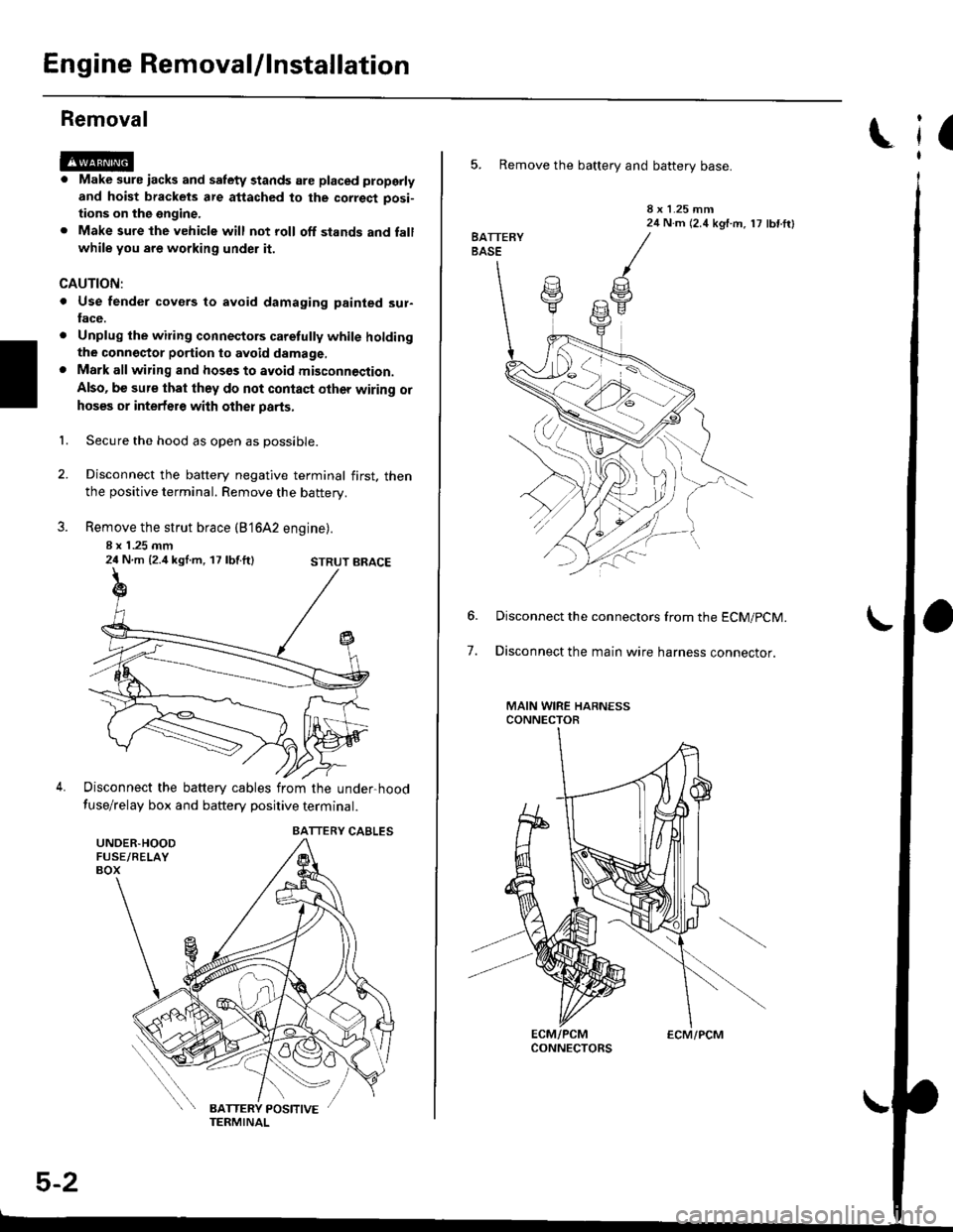
Secure the hood as open as possible.
Disconnect the battery negative terminal first. thenthe positive terminal. Remove the battery.
Remove the strut brace (B'16A2 engine).
8 x 1 .25 mm24 N.m {2.4 kgl.m, 17 lbf.ft}
Disconnect the battery cables from the under-hood
fuse/relay box and battery positive terminal.
STRUT BRACE
UNDER.HOODFUSE/RELAYBOX
BATTERY CABLES
5-2
ECM/PCM
(
5. Remove the battery and battery base.
8 x 1.25 mm24 N.m (2.4 kgf.m, 17 lbf ftl
7.
Disconnect the connectors from the ECM/pCM.
Disconnect the main wire harness connector.
MAIN WIRE HARNESSCONNECTOR
Page 177 of 2189

Removal
Engine removal is not required for this procedure.
!@@ Make sure jacks and safety stands are placed
properly and hoist brackels are attached to correst posi-
tion on the engine,
CAUTION:
o Use fender covers to avoid damaging painted sur-
faces.
To avoid damage, unplug the wiling connectors
carelully while holding the connector portion.
To avoid damaging the cylinder head, wait until the
engine coolant temperature drops below 100"F {38'Cl
before loosening the retaining bolt.
NOTE:
. Unspecified items are common.
. Mark all wiring and hoses to avoid misconnection.
AIso, be sure that they do not contact other wiring or
hoses or interfere with other parts.
o Inspect the timing belt before removing the cylinder
n eao.
. Turn the crankshaft pulley so that the No. 1 piston is
at top dead center (see page 6-64).
1. Disconnect the negative terminal from the battery.
Drain the engine coolant {see page 10-7).
. Remove the radiator cap to speed draining.
Remove the strut brace (see page 5-2).
Remove the intake air duct and air cleaner housing
(see page 5-3).
Remove the adjusting bolt and mounting bolt, then
remove the power steering (P/S) pump belt and pump
(see page 5 5).
2.
3.
4.
\
ADJUSTING
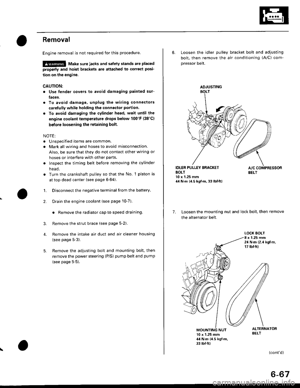
6. Loosen the idler pulley bracket bolt and adjusting
bolt, then remove the air conditioning (A/C) com-
pressor belt.
IDLER PULLEY BRACKETBOLT10 x 1.25 mm44 N.m {4.5 kg,l.m, 33 lbt.ft}
7. Loosen the mounting nut and lock bolt, then remove
the alternator belt.
LOCK BOLT8 x 1.25 mm24 N.m {2.4 kgf.m,17 tbtftl
ALTERNATORBELT10 x 1.25 mm,l,l N.m {4.5 kgf.m,33 tbf.ft,
(cont'd)
6-67
Page 1142 of 2189

Front Damper
Disassembly/lnspection
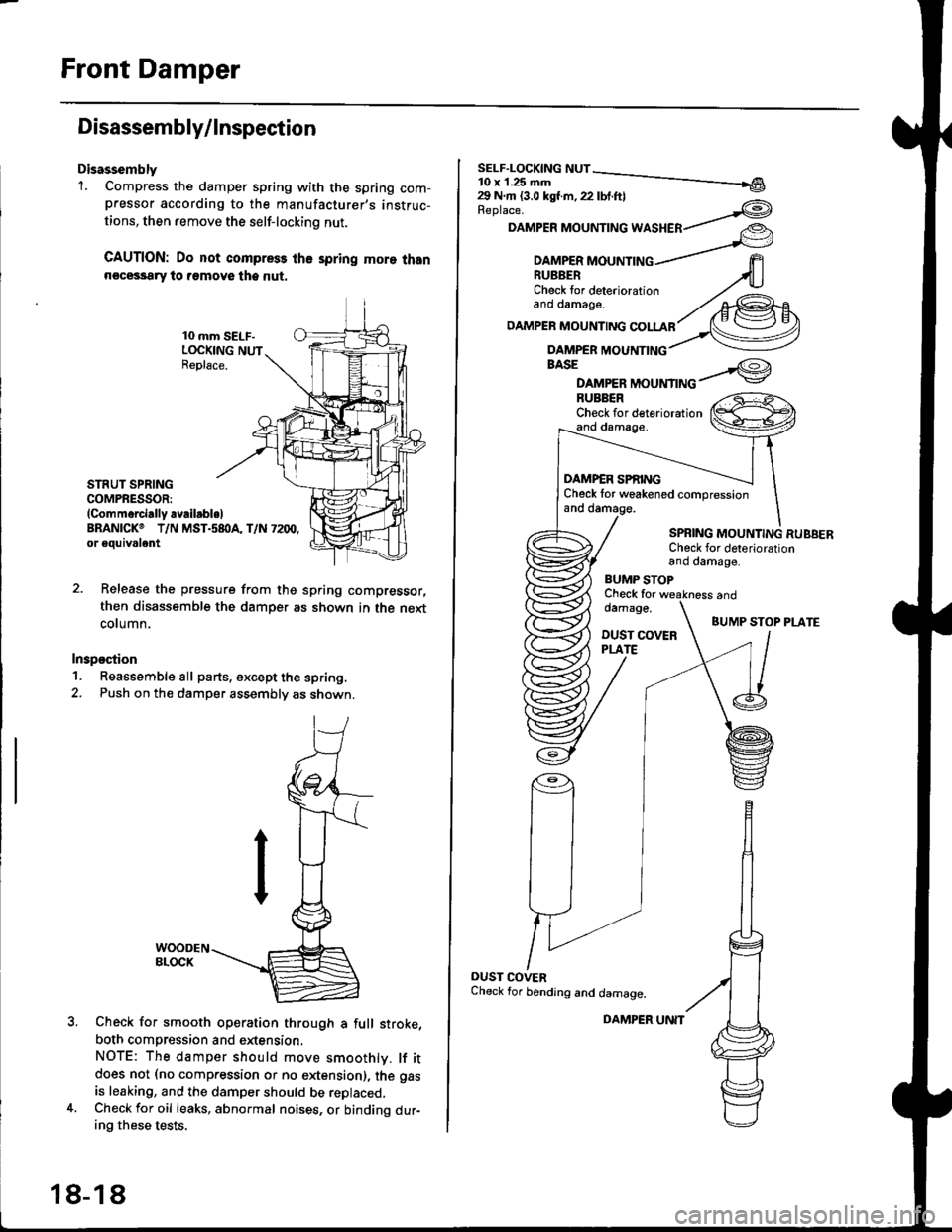
Disassembly'1. Compress the damper spring with the spring com-pressor according to the manufacturer,s instruc-
tions, then remove the self-lockino nut.
CAUTION: Do not compress the spring more thann€cessary to remove the nut.
10 mm SELF-LOCKING NUTReplace.
STRUT SPRINGCOMPRESSOR:(Commerci.lly availabl.lBRANICKO T/N MST.s8I}A, T/N 7200,or eouivalent
Release the pressure from thg spring compressor,
then disassemble the damper as shown in the next
column.
Inspostion
1. Reassemble all parts, except the spring.
2. Push on th€ damper assembly as shown.
Check for smooth operation through a full stroke,
both compression and extension,
NOTE: The damper should move smoothlv. lf itdoes not (no compression or no extension), the gas
is leaking, and the damper should be replaced.Check for oil leaks, abnormal noises, or binding dur-ing these tests.
18-18
DAMPER UNIT
Replace.
DAMPER MOUNTING WASHER
BASE
DAMPER MOUNTINGBUBBERCheck for deteriorationand damage.
DAMP€R SPf,INGCheck tor weakened compressionand damage.
SPBING MOUNTING RUBBERCheck for deteriorationand damage,
BUMP STOPCheck fordamage.
DUST COVERPLATE
and
BUMP STOP PLATE
OUST COVERCheck for bending and damage.
Page 1143 of 2189
\Reassembly
2.
't.
lr
Install the damper unit on a spring compressor.
Assemble the damper in reverse order of removal
except the damper mounting washer and self lock-
ing nut.
NOTE: Align the bottom of the damper spring and
spring lower seat as shown.
STRUTSPRING COMPRESSOR:
lcommercially availablelBRANICK@ T/N MST.58OA, T/N 7200,
or 6quival€nt
SPBING LOWER SEAT
Position the damper mounting base onto the
damper unit as shown.
Compress the damPer sPring.
Install the damper mounting rubber, damper mount-
ing washer, and a new 10 mm self-locking nut.
Hold the damper shaft. and tighten the 10 mm self-
locking nut.
SELF-LOCKING NUT10 x 1.25 mm29 N.m 13.0 kgf m, 22 lbf ft)
3.
4.
Replace.
DAMPERMOUNTING WASHER
(l-t
lnstallation
1. Loosely install the damper onto the frame with the
aligning tab facing inside. then loosely install the
two flange nuts.
FLANGE NUTS10 x 1 ,25 mm49 N.m (5.0 kgt'm, 36 lbf'ftl
DAMPER ASSEMBLY
{cont'd)
18-19
Page 1328 of 2189
Hatch
Adjustment
NOTE:
. Before adjusting the hatch, loosen each bolt and nut slightly.
a The suDport struts should be removed.
. To adjust, remove both hatch sidetrim (see page 20-63) and the rear roof trim (see page 20-65).
1. Adjust the hatch hinges right and left, as well as fore and aft. by using the elongated holes
2. Turn the hatch edge cushions, as necessary, to make the hatch fit flush with the body at each side.
3. Adjust the hatch fit to the hatch opening by moving the striker.
4. After adiustment, tighten each bolt and nut securely.
6x1.0mm9.8 N.m (1.0 kgf.m,
HATCHEDGE CUSHION
HATCHHINGERearward
HAEDGECUSHION
j ... 22
\,_1q
N.m (2.2 kgf.m,tbf.ftl
\
co
38Nm(3.9kgfm,2.8 rbf.ft)
NOTE: Move the striker right or left until it's centered in
the hatch latch. as shown.
HATCHHINGESTRIKER
l0x1VER
HATCHEDGECUSHION
9.8 N.m 11.0 kst.m,7.2 tbf.ft)HATCHLATCH
20-98
6x1.0mm