2000 DODGE NEON ignition switch
[x] Cancel search: ignition switchPage 757 of 1285
INSPECT CYLINDER HEAD FOR THE FOLLOWING:
NOTE:
²Check oil feed holes for blockage.
²Inspect cylinder head camshaft bearings for
wear, Refer to Cylinder Head, Inspection and Clean-
ing.
²Check camshaft bearing journals for scratches
and worn areas. If light scratches are present, they
may be removed with 400 grit sand paper. If deep
scratches are present, replace the camshaft and
check the cylinder head for damage. Replace the
cylinder head if worn or damaged. Check the lobes
for pitting and wear. If the lobes show signs of
wear, check the corresponding rocker arm roller for
wear or damage. Replace rocker arm/hydraulic lash
adjuster if worn or damaged. If lobes show signs of
pitting on the nose, flank or base circle; replace the
camshaft.
INSTALLATION
(1) Lubricate the camshaft journals with oil and
install camshaftwithoutrocker arm assemblies
installed.
(2) Install camshaft target magnet into the end of
the camshaft. Tighten mounting screw to 3.4 N´m (30
in. lbs.).
(3) Install camshaft position sensor and tighten
mounting screws to 9 N´m (80 in. lbs.).
(4) Measure camshaft end play using the following
procedure:
(a) Mount dial indicator C-3339 or equivalent, to
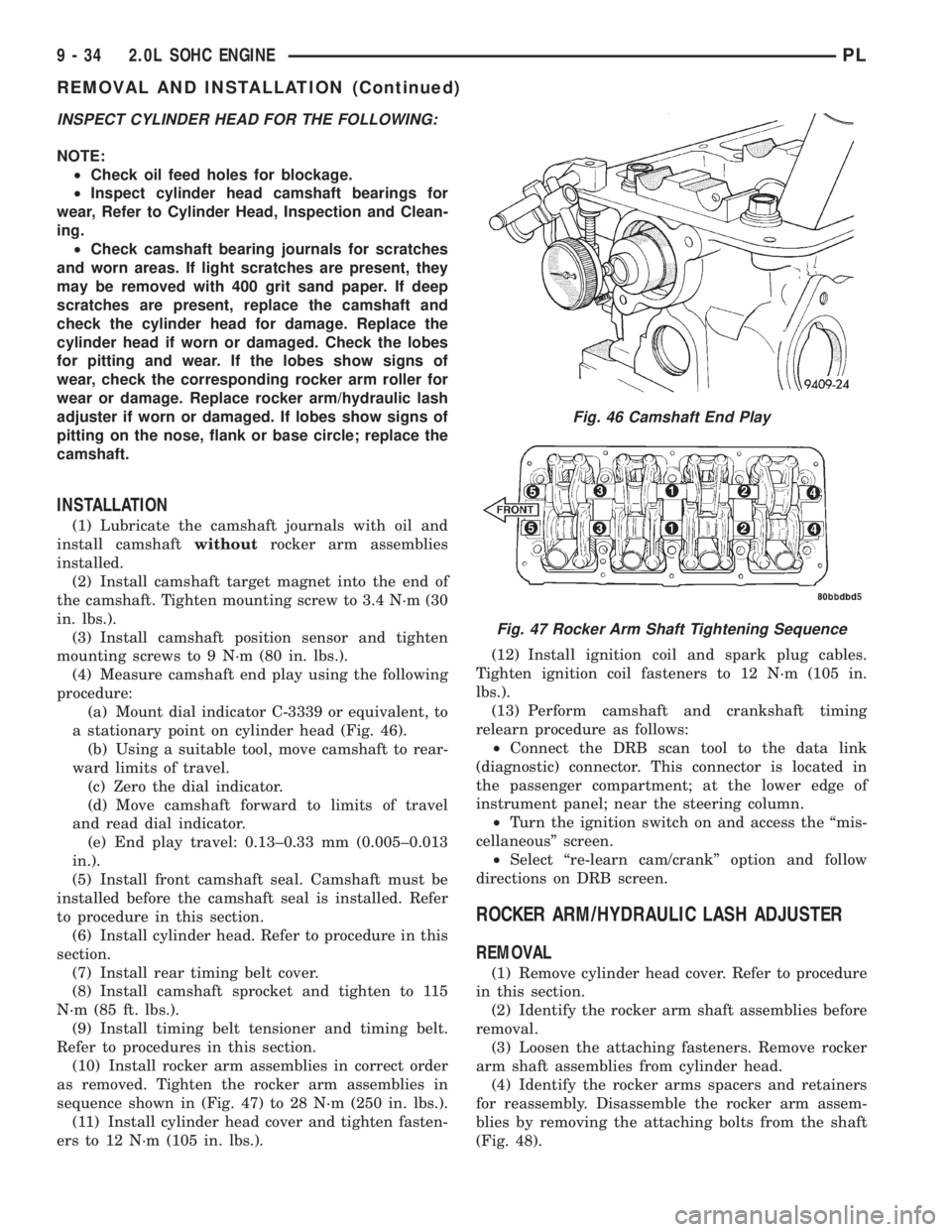
a stationary point on cylinder head (Fig. 46).
(b) Using a suitable tool, move camshaft to rear-
ward limits of travel.
(c) Zero the dial indicator.
(d) Move camshaft forward to limits of travel
and read dial indicator.
(e) End play travel: 0.13±0.33 mm (0.005±0.013
in.).
(5) Install front camshaft seal. Camshaft must be
installed before the camshaft seal is installed. Refer
to procedure in this section.
(6) Install cylinder head. Refer to procedure in this
section.
(7) Install rear timing belt cover.
(8) Install camshaft sprocket and tighten to 115
N´m (85 ft. lbs.).
(9) Install timing belt tensioner and timing belt.
Refer to procedures in this section.
(10) Install rocker arm assemblies in correct order
as removed. Tighten the rocker arm assemblies in
sequence shown in (Fig. 47) to 28 N´m (250 in. lbs.).
(11) Install cylinder head cover and tighten fasten-
ers to 12 N´m (105 in. lbs.).(12) Install ignition coil and spark plug cables.
Tighten ignition coil fasteners to 12 N´m (105 in.
lbs.).
(13) Perform camshaft and crankshaft timing
relearn procedure as follows:
²Connect the DRB scan tool to the data link
(diagnostic) connector. This connector is located in
the passenger compartment; at the lower edge of
instrument panel; near the steering column.
²Turn the ignition switch on and access the ªmis-
cellaneousº screen.
²Select ªre-learn cam/crankº option and follow
directions on DRB screen.
ROCKER ARM/HYDRAULIC LASH ADJUSTER
REMOVAL
(1) Remove cylinder head cover. Refer to procedure
in this section.
(2) Identify the rocker arm shaft assemblies before
removal.
(3) Loosen the attaching fasteners. Remove rocker
arm shaft assemblies from cylinder head.
(4) Identify the rocker arms spacers and retainers
for reassembly. Disassemble the rocker arm assem-
blies by removing the attaching bolts from the shaft
(Fig. 48).
Fig. 46 Camshaft End Play
Fig. 47 Rocker Arm Shaft Tightening Sequence
9 - 34 2.0L SOHC ENGINEPL
REMOVAL AND INSTALLATION (Continued)
Page 763 of 1285

(13) Install ignition coil and spark plug cables.
Connect coil electrical connector.
(14) Install intake manifold. Refer to procedure in
this section.
(15) Install upper radiator hose.
(16) Install ground wire to cylinder head.
(17) Install coolant recovery container.
(18) Connect fuel line to fuel rail.
(19) Install rear timing belt cover, camshaft
sprocket, and timing belt tensioner and timing belt.
Refer to procedures in this section.
(20) Install front timing belt cover.
(21) Install engine mount bracket.
(22) Position engine and install right side engine
mount to engine mount bracket bolt. Tighten bolt to
118 N´m (87 ft. lbs.). Remove jack from beneath
engine.
(23) Install power steering pump assembly.
(24) Install power steering hose support clip and
ground strap to engine mount bracket.
(25) Install upper torque strut.
(26) Raise vehicle.
(27) Install lower torque strut.
(28) Install crankshaft damper.
(29) Install accessory drive belts. Refer to Group 7,
Cooling System Accessory Drive Belt for procedure.
(30) Install right side splash shield and front
wheel.
(31) Install exhaust pipe to exhaust manifold
flange.
(32) Lower vehicle and fill cooling system. Refer to
Group 7, Cooling System for procedure.
(33) Connect negative cable to battery.
(34) Perform camshaft and crankshaft timing
relearn procedure as follows:
²Connect the DRB scan tool to the data link
(diagnostic) connector. This connector is located in
the passenger compartment; at the lower edge of
instrument panel; near the steering column.
²Turn the ignition switch on and access the ªmis-
cellaneousº screen.
²Select ªre-learn cam/crankº option and follow
directions on DRB screen.
CRANKSHAFT DAMPER
REMOVAL
(1) Remove accessory drive belts. Refer to Group 7,
Cooling System for procedure.
(2) Raise vehicle on a hoist and remove right inner
splash shield.
(3) Remove crankshaft damper bolt. Remove
damper using the large side of Special Tool 1026 and
insert 6827-A (Fig. 61).
INSTALLATION
(1) Install crankshaft damper using M12±1.75 x
150 mm bolt, washer, thrust bearing and nut from
Special Tool 6792 (Fig. 62).
Fig. 62 Crankshaft DamperÐInstallation
1 ± M12 Ð 1.753150 MM BOLT, WASHER AND THRUST
BEARING FROM SPECIAL TOOL 6792
Fig. 60 Cylinder Head Tightening Sequence
Fig. 61 Crankshaft DamperÐRemoval
1 ± SPECIAL TOOL 6827±A INSERT
2 ± SPECIAL TOOL 1026 THREE JAW PULLER
9 - 40 2.0L SOHC ENGINEPL
REMOVAL AND INSTALLATION (Continued)
Page 769 of 1285
(10) Install right engine mount to engine mount
bracket through bolt.
(11) Remove jack from under engine.
(12) Install upper torque strut.
(13) Install power steering pump assembly.
(14) Raise vehicle and install lower torque strut.
(15) Install crankshaft damper using M12-1.75 x
150 mm bolt, washer, thrust bearing and nut from
Special Tool 6792. Install crankshaft damper bolt and
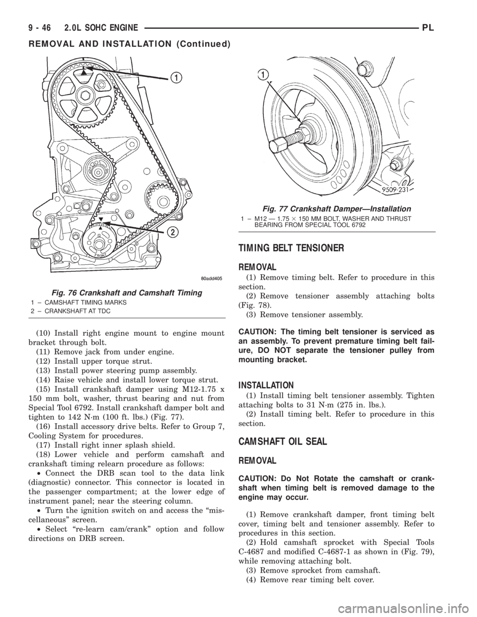
tighten to 142 N´m (100 ft. lbs.) (Fig. 77).
(16) Install accessory drive belts. Refer to Group 7,
Cooling System for procedures.
(17) Install right inner splash shield.
(18) Lower vehicle and perform camshaft and
crankshaft timing relearn procedure as follows:
²Connect the DRB scan tool to the data link
(diagnostic) connector. This connector is located in
the passenger compartment; at the lower edge of
instrument panel; near the steering column.
²Turn the ignition switch on and access the ªmis-
cellaneousº screen.
²Select ªre-learn cam/crankº option and follow
directions on DRB screen.
TIMING BELT TENSIONER
REMOVAL
(1) Remove timing belt. Refer to procedure in this
section.
(2) Remove tensioner assembly attaching bolts
(Fig. 78).
(3) Remove tensioner assembly.
CAUTION: The timing belt tensioner is serviced as
an assembly. To prevent premature timing belt fail-
ure, DO NOT separate the tensioner pulley from
mounting bracket.
INSTALLATION
(1) Install timing belt tensioner assembly. Tighten
attaching bolts to 31 N´m (275 in. lbs.).
(2) Install timing belt. Refer to procedure in this
section.
CAMSHAFT OIL SEAL
REMOVAL
CAUTION: Do Not Rotate the camshaft or crank-
shaft when timing belt is removed damage to the
engine may occur.
(1) Remove crankshaft damper, front timing belt
cover, timing belt and tensioner assembly. Refer to
procedures in this section.
(2) Hold camshaft sprocket with Special Tools
C-4687 and modified C-4687-1 as shown in (Fig. 79),
while removing attaching bolt.
(3) Remove sprocket from camshaft.
(4) Remove rear timing belt cover.
Fig. 76 Crankshaft and Camshaft Timing
1 ± CAMSHAFT TIMING MARKS
2 ± CRANKSHAFT AT TDC
Fig. 77 Crankshaft DamperÐInstallation
1 ± M12 Ð 1.753150 MM BOLT, WASHER AND THRUST
BEARING FROM SPECIAL TOOL 6792
9 - 46 2.0L SOHC ENGINEPL
REMOVAL AND INSTALLATION (Continued)
Page 778 of 1285
(17) Install rear timing belt cover and camshaft
sprocket.
(18) Install crankshaft sprocket, timing belt ten-
sioner, timing belt, and cover.
(19) Install front engine mount bracket.
(20) Remove engine from repair stand and position
on Special Tools 6135 and 6710 Engine Dolly and
Cradle. Install safety straps around the engine to
cradle and tighten and lock them into position.
(21) Install crankshaft rear oil seal. Refer to proce-
dure in this section.
(22) Install drive plate/flywheel. Apply Mopart
Lock & Seal Adhesive to bolt threads and tighten to
95 N´m (70 ft. lbs.).
(23) Install transaxle to engine.
(24) Install structural collar. Refer to procedure in
this section.
(25) Install engine assembly. Refer to procedure in
this section.
(26) Perform camshaft and crankshaft timing
relearn procedure as follows:
²Connect the DRB scan tool to the data link
(diagnostic) connector. This connector is located in
the passenger compartment; at the lower edge of
instrument panel; near the steering column.
²Turn the ignition switch on and access the ªmis-
cellaneousº screen.
²Select ªre-learn cam/crankº option and follow
directions on DRB screen.
OIL FILTER ADAPTER
REMOVE AND INSTALL
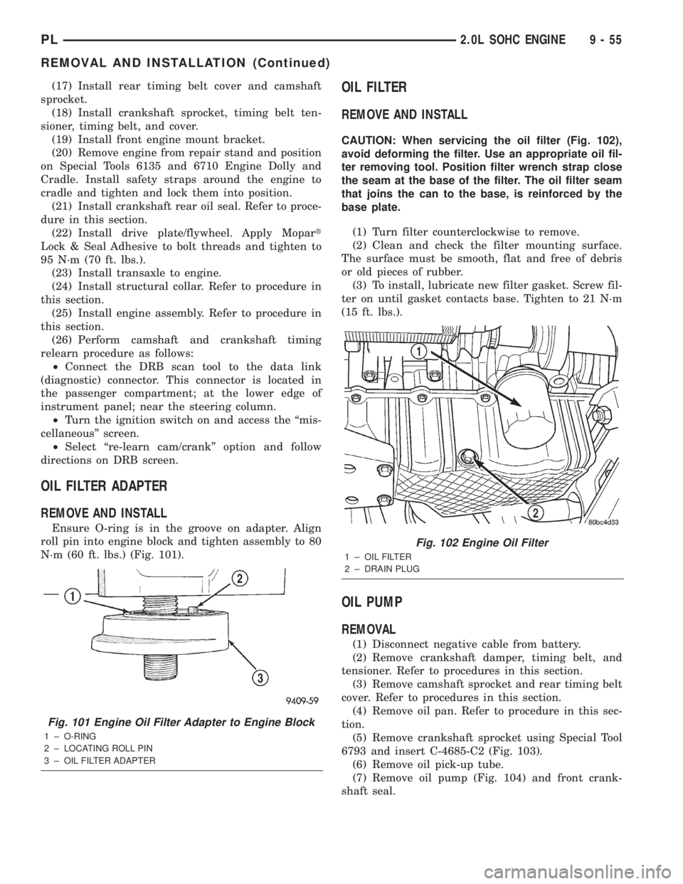
Ensure O-ring is in the groove on adapter. Align
roll pin into engine block and tighten assembly to 80
N´m (60 ft. lbs.) (Fig. 101).
OIL FILTER
REMOVE AND INSTALL
CAUTION: When servicing the oil filter (Fig. 102),
avoid deforming the filter. Use an appropriate oil fil-
ter removing tool. Position filter wrench strap close
the seam at the base of the filter. The oil filter seam
that joins the can to the base, is reinforced by the
base plate.
(1) Turn filter counterclockwise to remove.
(2) Clean and check the filter mounting surface.
The surface must be smooth, flat and free of debris
or old pieces of rubber.
(3) To install, lubricate new filter gasket. Screw fil-
ter on until gasket contacts base. Tighten to 21 N´m
(15 ft. lbs.).
OIL PUMP
REMOVAL
(1) Disconnect negative cable from battery.
(2) Remove crankshaft damper, timing belt, and
tensioner. Refer to procedures in this section.
(3) Remove camshaft sprocket and rear timing belt
cover. Refer to procedures in this section.
(4) Remove oil pan. Refer to procedure in this sec-
tion.
(5) Remove crankshaft sprocket using Special Tool
6793 and insert C-4685-C2 (Fig. 103).
(6) Remove oil pick-up tube.
(7) Remove oil pump (Fig. 104) and front crank-
shaft seal.
Fig. 101 Engine Oil Filter Adapter to Engine Block
1 ± O-RING
2 ± LOCATING ROLL PIN
3 ± OIL FILTER ADAPTER
Fig. 102 Engine Oil Filter
1 ± OIL FILTER
2 ± DRAIN PLUG
PL2.0L SOHC ENGINE 9 - 55
REMOVAL AND INSTALLATION (Continued)
Page 831 of 1285
(3) Squeeze retainer tabs together and pull fuel
tube/quick-connect fitting assembly off of fuel tube
nipple. The retainer will remain on fuel tube.
INSTALLATION
CAUTION: Never install a quick-connect fitting
without the retainer being either on the fuel tube or
already in the quick-connect fitting. In either case,
ensure the retainer locks securely into the quick-
connect fitting by firmly pulling on fuel tube and fit-
ting to ensure it is secured.
(1) Using a clean lint free cloth, clean the fuel tube
nipple and retainer.
(2) Prior to connecting the fitting to the fuel tube,
coat the fuel tube nipple with clean 30 weight engine
oil.
(3) Push the quick-connect fitting over the fuel
tube until theretainer seats and a click is heard.
(4) The plastic quick-connect fitting has windows
in the sides of the casing. When the fitting com-
pletely attaches to the fuel tube, the retainer locking
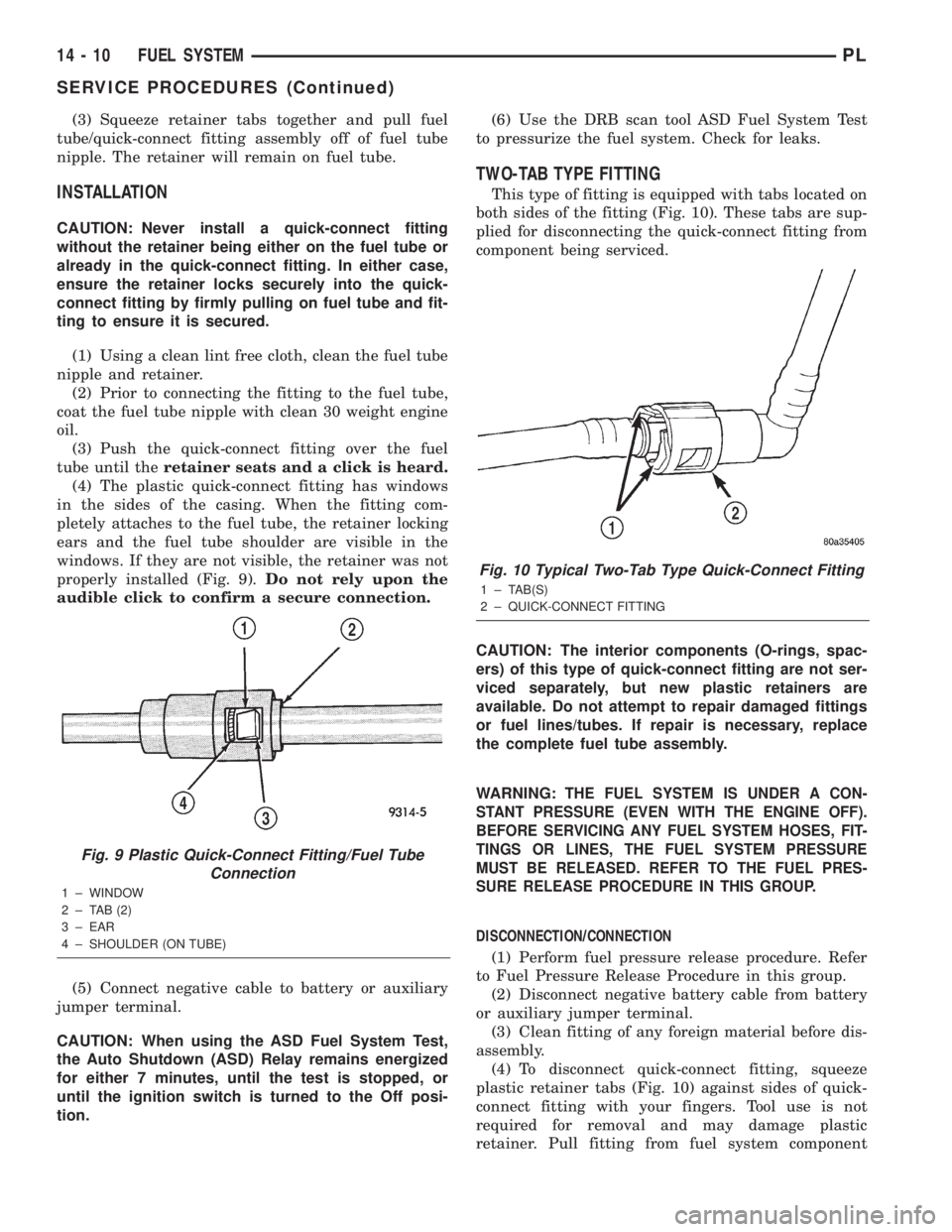
ears and the fuel tube shoulder are visible in the
windows. If they are not visible, the retainer was not
properly installed (Fig. 9).Do not rely upon the
audible click to confirm a secure connection.
(5) Connect negative cable to battery or auxiliary
jumper terminal.
CAUTION: When using the ASD Fuel System Test,
the Auto Shutdown (ASD) Relay remains energized
for either 7 minutes, until the test is stopped, or
until the ignition switch is turned to the Off posi-
tion.(6) Use the DRB scan tool ASD Fuel System Test
to pressurize the fuel system. Check for leaks.
TWO-TAB TYPE FITTING
This type of fitting is equipped with tabs located on
both sides of the fitting (Fig. 10). These tabs are sup-
plied for disconnecting the quick-connect fitting from
component being serviced.
CAUTION: The interior components (O-rings, spac-
ers) of this type of quick-connect fitting are not ser-
viced separately, but new plastic retainers are
available. Do not attempt to repair damaged fittings
or fuel lines/tubes. If repair is necessary, replace
the complete fuel tube assembly.
WARNING:
THE FUEL SYSTEM IS UNDER A CON-
STANT PRESSURE (EVEN WITH THE ENGINE OFF).
BEFORE SERVICING ANY FUEL SYSTEM HOSES, FIT-
TINGS OR LINES, THE FUEL SYSTEM PRESSURE
MUST BE RELEASED. REFER TO THE FUEL PRES-
SURE RELEASE PROCEDURE IN THIS GROUP.
DISCONNECTION/CONNECTION
(1) Perform fuel pressure release procedure. Refer
to Fuel Pressure Release Procedure in this group.
(2) Disconnect negative battery cable from battery
or auxiliary jumper terminal.
(3) Clean fitting of any foreign material before dis-
assembly.
(4) To disconnect quick-connect fitting, squeeze
plastic retainer tabs (Fig. 10) against sides of quick-
connect fitting with your fingers. Tool use is not
required for removal and may damage plastic
retainer. Pull fitting from fuel system component
Fig. 9 Plastic Quick-Connect Fitting/Fuel Tube
Connection
1 ± WINDOW
2 ± TAB (2)
3 ± EAR
4 ± SHOULDER (ON TUBE)
Fig. 10 Typical Two-Tab Type Quick-Connect Fitting
1 ± TAB(S)
2 ± QUICK-CONNECT FITTING
14 - 10 FUEL SYSTEMPL
SERVICE PROCEDURES (Continued)
Page 838 of 1285

(7) Disconnect fuel pump module electrical connec-
tor and ground wire (Fig. 31).
(8) Disconnect the fuel tube from Fuel Filter/Reg-
ulator. Refer to Quick Connect Fittings in the Fuel
Delivery section of this group.
(9) Disconnect fuel filler tube and filler vent tube
from filler hose at fuel tank.
(10) Support tank with transmission jack. Loosen
tank mounting straps and lower tank slightly.
(11) Remove tank mounting straps and lower tank.
INSTALLATION
(1) Position fuel tank on transmission jack.
(2) Raise tank into position.
(3) Tighten fuel tank strap nuts to 22.5 N´m (200
in. lbs.) torque. Remove transmission jack. Ensure
straps are not twisted or bent.(4) Connect fuel filler tube tank inlet nipple.
Tighten clamp.
(5) Connect EVAP vent hose.
(6) Attach fuel tubes to pump module and chassis
fuel tube. Refer to Quick Connect Fittings in the Fuel
Delivery section of this Group.
(7) Attach electrical connector and ground wire to
fuel pump module.
(8) Install vapor lines to EVAP canister.
(9) Install EVAP canister.
(10) Lower vehicle.
(11) Fill fuel tank, install filler cap, and connect
battery cable.
CAUTION: When using the ASD Fuel System Test,
the Auto Shutdown (ASD) Relay remains energized
for either 7 minutes, until the test is stopped, or
until the ignition switch is turned to the Off posi-
tion.
(12) Use the DRB scan tool ASD Fuel System Test
to pressurize the fuel system. Check for leaks.
FUEL FILLER NECK
REMOVAL
(1) Loosen fuel filler tube cap.
(2) Remove fuel filler neck screws (Fig. 32).
(3) Raise and support vehicle.
(4) Remove splash shield from wheel well.
(5) Disconnect fuel fill vapor tube.
(6) Disconnect fuel filler tube from fuel tank.
(7) Remove groundstrap from body.
(8) Remove filler neck (Fig. 33).
Fig. 29 EVAP Canister
Fig. 30 Fuel Tank
Fig. 31 Pump Module Electrical Connector
1 ± ELECTRICAL CONNECTOR
2 ± FUEL LINE
PLFUEL SYSTEM 14 - 17
REMOVAL AND INSTALLATION (Continued)
Page 842 of 1285
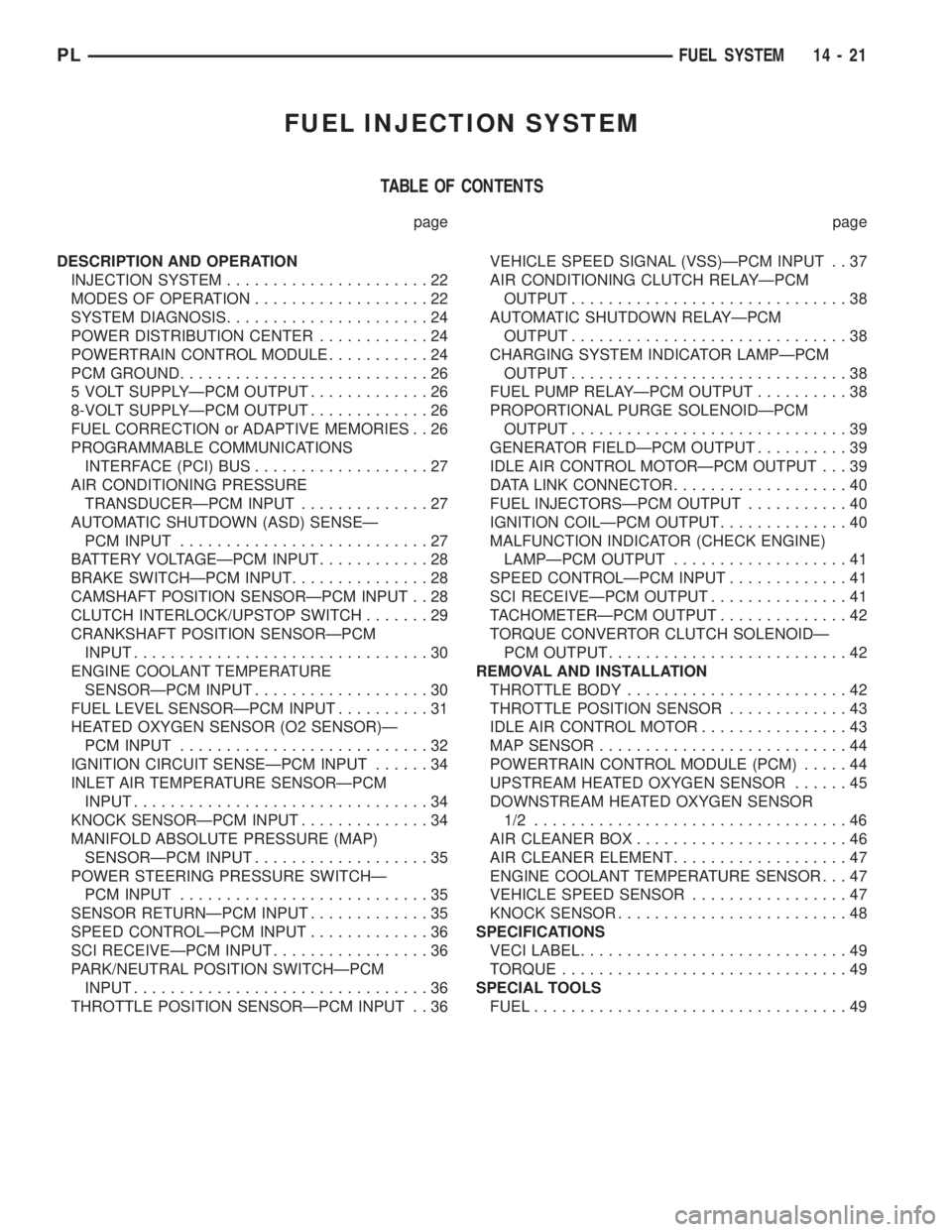
FUEL INJECTION SYSTEM
TABLE OF CONTENTS
page page
DESCRIPTION AND OPERATION
INJECTION SYSTEM......................22
MODES OF OPERATION...................22
SYSTEM DIAGNOSIS......................24
POWER DISTRIBUTION CENTER............24
POWERTRAIN CONTROL MODULE...........24
PCM GROUND...........................26
5 VOLT SUPPLYÐPCM OUTPUT.............26
8-VOLT SUPPLYÐPCM OUTPUT.............26
FUEL CORRECTION or ADAPTIVE MEMORIES . . 26
PROGRAMMABLE COMMUNICATIONS
INTERFACE (PCI) BUS...................27
AIR CONDITIONING PRESSURE
TRANSDUCERÐPCM INPUT..............27
AUTOMATIC SHUTDOWN (ASD) SENSEÐ
PCM INPUT...........................27
BATTERY VOLTAGEÐPCM INPUT............28
BRAKE SWITCHÐPCM INPUT...............28
CAMSHAFT POSITION SENSORÐPCM INPUT . . 28
CLUTCH INTERLOCK/UPSTOP SWITCH.......29
CRANKSHAFT POSITION SENSORÐPCM
INPUT................................30
ENGINE COOLANT TEMPERATURE
SENSORÐPCM INPUT...................30
FUEL LEVEL SENSORÐPCM INPUT..........31
HEATED OXYGEN SENSOR (O2 SENSOR)Ð
PCM INPUT...........................32
IGNITION CIRCUIT SENSEÐPCM INPUT......34
INLET AIR TEMPERATURE SENSORÐPCM
INPUT................................34
KNOCK SENSORÐPCM INPUT..............34
MANIFOLD ABSOLUTE PRESSURE (MAP)
SENSORÐPCM INPUT...................35
POWER STEERING PRESSURE SWITCHÐ
PCM INPUT...........................35
SENSOR RETURNÐPCM INPUT.............35
SPEED CONTROLÐPCM INPUT.............36
SCI RECEIVEÐPCM INPUT.................36
PARK/NEUTRAL POSITION SWITCHÐPCM
INPUT................................36
THROTTLE POSITION SENSORÐPCM INPUT . . 36VEHICLE SPEED SIGNAL (VSS)ÐPCM INPUT . . 37
AIR CONDITIONING CLUTCH RELAYÐPCM
OUTPUT..............................38
AUTOMATIC SHUTDOWN RELAYÐPCM
OUTPUT..............................38
CHARGING SYSTEM INDICATOR LAMPÐPCM
OUTPUT..............................38
FUEL PUMP RELAYÐPCM OUTPUT..........38
PROPORTIONAL PURGE SOLENOIDÐPCM
OUTPUT..............................39
GENERATOR FIELDÐPCM OUTPUT..........39
IDLE AIR CONTROL MOTORÐPCM OUTPUT . . . 39
DATA LINK CONNECTOR...................40
FUEL INJECTORSÐPCM OUTPUT...........40
IGNITION COILÐPCM OUTPUT..............40
MALFUNCTION INDICATOR (CHECK ENGINE)
LAMPÐPCM OUTPUT...................41
SPEED CONTROLÐPCM INPUT.............41
SCI RECEIVEÐPCM OUTPUT...............41
TACHOMETERÐPCM OUTPUT..............42
TORQUE CONVERTOR CLUTCH SOLENOIDÐ
PCM OUTPUT..........................42
REMOVAL AND INSTALLATION
THROTTLE BODY........................42
THROTTLE POSITION SENSOR.............43
IDLE AIR CONTROL MOTOR................43
MAP SENSOR...........................44
POWERTRAIN CONTROL MODULE (PCM).....44
UPSTREAM HEATED OXYGEN SENSOR......45
DOWNSTREAM HEATED OXYGEN SENSOR
1/2 ..................................46
AIR CLEANER BOX.......................46
AIR CLEANER ELEMENT...................47
ENGINE COOLANT TEMPERATURE SENSOR . . . 47
VEHICLE SPEED SENSOR.................47
KNOCK SENSOR.........................48
SPECIFICATIONS
VECI LABEL.............................49
TORQUE...............................49
SPECIAL TOOLS
FUEL..................................49
PLFUEL SYSTEM 14 - 21
Page 843 of 1285
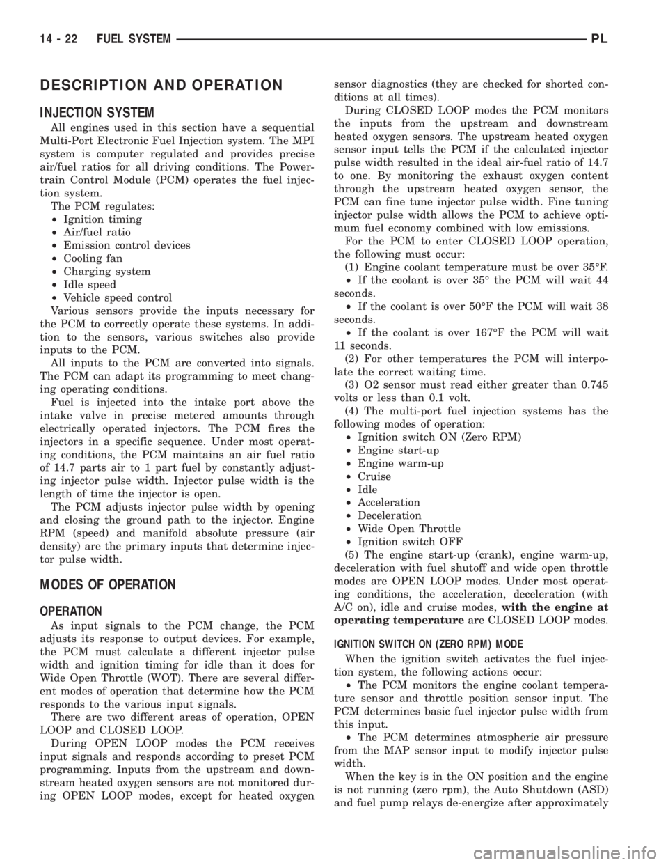
DESCRIPTION AND OPERATION
INJECTION SYSTEM
All engines used in this section have a sequential
Multi-Port Electronic Fuel Injection system. The MPI
system is computer regulated and provides precise
air/fuel ratios for all driving conditions. The Power-
train Control Module (PCM) operates the fuel injec-
tion system.
The PCM regulates:
²Ignition timing
²Air/fuel ratio
²Emission control devices
²Cooling fan
²Charging system
²Idle speed
²Vehicle speed control
Various sensors provide the inputs necessary for
the PCM to correctly operate these systems. In addi-
tion to the sensors, various switches also provide
inputs to the PCM.
All inputs to the PCM are converted into signals.
The PCM can adapt its programming to meet chang-
ing operating conditions.
Fuel is injected into the intake port above the
intake valve in precise metered amounts through
electrically operated injectors. The PCM fires the
injectors in a specific sequence. Under most operat-
ing conditions, the PCM maintains an air fuel ratio
of 14.7 parts air to 1 part fuel by constantly adjust-
ing injector pulse width. Injector pulse width is the
length of time the injector is open.
The PCM adjusts injector pulse width by opening
and closing the ground path to the injector. Engine
RPM (speed) and manifold absolute pressure (air
density) are the primary inputs that determine injec-
tor pulse width.
MODES OF OPERATION
OPERATION
As input signals to the PCM change, the PCM
adjusts its response to output devices. For example,
the PCM must calculate a different injector pulse
width and ignition timing for idle than it does for
Wide Open Throttle (WOT). There are several differ-
ent modes of operation that determine how the PCM
responds to the various input signals.
There are two different areas of operation, OPEN
LOOP and CLOSED LOOP.
During OPEN LOOP modes the PCM receives
input signals and responds according to preset PCM
programming. Inputs from the upstream and down-
stream heated oxygen sensors are not monitored dur-
ing OPEN LOOP modes, except for heated oxygensensor diagnostics (they are checked for shorted con-
ditions at all times).
During CLOSED LOOP modes the PCM monitors
the inputs from the upstream and downstream
heated oxygen sensors. The upstream heated oxygen
sensor input tells the PCM if the calculated injector
pulse width resulted in the ideal air-fuel ratio of 14.7
to one. By monitoring the exhaust oxygen content
through the upstream heated oxygen sensor, the
PCM can fine tune injector pulse width. Fine tuning
injector pulse width allows the PCM to achieve opti-
mum fuel economy combined with low emissions.
For the PCM to enter CLOSED LOOP operation,
the following must occur:
(1) Engine coolant temperature must be over 35ÉF.
²If the coolant is over 35É the PCM will wait 44
seconds.
²If the coolant is over 50ÉF the PCM will wait 38
seconds.
²If the coolant is over 167ÉF the PCM will wait
11 seconds.
(2) For other temperatures the PCM will interpo-
late the correct waiting time.
(3) O2 sensor must read either greater than 0.745
volts or less than 0.1 volt.
(4) The multi-port fuel injection systems has the
following modes of operation:
²Ignition switch ON (Zero RPM)
²Engine start-up
²Engine warm-up
²Cruise
²Idle
²Acceleration
²Deceleration
²Wide Open Throttle
²Ignition switch OFF
(5) The engine start-up (crank), engine warm-up,
deceleration with fuel shutoff and wide open throttle
modes are OPEN LOOP modes. Under most operat-
ing conditions, the acceleration, deceleration (with
A/C on), idle and cruise modes,with the engine at
operating temperatureare CLOSED LOOP modes.
IGNITION SWITCH ON (ZERO RPM) MODE
When the ignition switch activates the fuel injec-
tion system, the following actions occur:
²The PCM monitors the engine coolant tempera-
ture sensor and throttle position sensor input. The
PCM determines basic fuel injector pulse width from
this input.
²The PCM determines atmospheric air pressure
from the MAP sensor input to modify injector pulse
width.
When the key is in the ON position and the engine
is not running (zero rpm), the Auto Shutdown (ASD)
and fuel pump relays de-energize after approximately
14 - 22 FUEL SYSTEMPL