2.7 To install the xenon wiring harness (US cars only)
The xenon wiring harness is to be secured using cable ties.
Ensure that cables and other lines are not kinked or damaged when they are being installed in the car and that
they do not impair the freedom of movement of other components.
If the specified pins or chambers are already in use, bridges, double crimps or parallel end stops are to be
used.
Fold out folded page 2-129
A
Overview of connection points
Branch A(X991, 26-pin plug, Bordeaux) is to be connected to the control module for the automatic headlight
adjustment control system on the module holder behind the glove box.
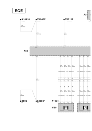
Branch B1(triple joint connector X10466*) is to be fitted in the connector box behind the glove box.
Branch B2(white/red/yellow cable) is to be connected to the K-BUS terminal connector (X10116) behind the glove
box.
Branch C1(triple joint connector X1608*) is to be fitted in the connector box behind the glove box.
Branch C2(brown/black cable) is to be connected to the terminal 31 connector (X596) behind the glove box.
Branch D(yellow/red cable) is to be connected to slot 27 in the light module (X10117, 54-pin, black) on the A pillar
on the passenger side.
Branch E(blue/red cable) is to be connected to the blue/red cable from pin 25 on the light module (X10117,
54-pin, black) using a double mini connector.
The rubber grommet (F) is used to seal the cable passage on the floor of the boot.
Cable G1, grey/white cable, is to be connected to slot 2 of branch G(X1451, 6-pin, black), cable G2, grey/brown
cable, to slot 3 and cable G3, grey/green cable, to slot 6. Any cables in the car for the level sensor are to be
repinned (see section 2.7-F). Branch Gis then to be connected to the level sensor at the rear right.
Cable H1, yellow/red cable, is to be connected to slot 1 of branch H(X1034, 4-pin, natural), cable H2,
yellow/brown cable, to slot 2, cable H3, blue/red cable, to slot 3 and cable H4, blue/brown cable, to slot 4. Branch
His to be connected to the servo motor on the left Xenon headlight.
Branch I(yellow/white cable) is to be connected to slot 18 of the ABS/DSC control module in the front left of the
engine compartment in cars with an optional equipment wiring harness up to level 2. In cars with an optional
equipment wiring harness above level 2, there is a yellow/white cable in the boot at the rear left on the 6-pin plug
X1310S on slot 2, which comes from the ABS/DSC control module, slot 18. Connect branch I(yellow/white cable)
to this cable using a double mini connector.
Cable J1, black/white cable, is to be connected to slot 2 of branch J (X10275, 6-pin, black), cable J2, black/grey
cable, to slot 3 and cable J3, black/green cable, to slot 6. Any cables in the car for the air suspension are to be
repinned (see section 2.7-F). Branch Jis then to be connected to the level sensor at the front right.
Cable K1, yellow/black cable, is to be connected to slot 1 of branch K (X1035, 4-pin, natural), cable K2,
yellow/brown cable, to slot 2, cable K3, blue/black cable, to slot 3 and cable K4, blue/brown cable, to slot 4.
Branch Kis to be connected to the servo motor on the right Xenon headlight.
B
Connect the control module for the automatic headlight adjustment control system (1) to the module holder behind
the glove box. Connect branch A(X991, 26-pin plug, Bordeaux) to the control module for the automatic headlight
adjustment control system (1) and secure it. The xenon wiring harness goes to the right and splits near the A pillar.
Branches B1to G3go downwards along the vehicle wiring harness, branches B1to C2then go to the
connector box (2).
Branches Hto K4go upwards along the vehicle wiring harness.
C
Release the connector box (2) and swing it forwards.
Unclip the Kbus multiple connector (X10116, white/red/yellow cables) (3) and terminal 31 multiple connector
(X596, brown/black cables) (4).
If there are any unoccupied slots in the multiple connectors X10116 (3) and X596 (4), connect branches B2,
white/red/yellow cable, and C2, brown/black cable, to the corresponding cable colours.
The procedure if all the slots are occupied is described for multiple connector X10116 (3). If necessary
proceed accordingly for multiple connector X596 (4).
Disconnect a white/red/yellow cable from multiple connector X10116 (3) and connect it to the triple connector
X10466* (B1). Connect branch B2, white/red/yellow cable, to the now unoccupied slot on multiple connector
X10116 (3).
EN/2-101
Clip multiple connectors X10116 (3), X10466* (B1), X596 (4) and X1608* (C1) into the connector box (2) and mount
the connector box (2) on the module holder.
D
Disconnect the 54-pin black plug X10117 (5) from the light module (6) on the A pillar on the passenger side and
take the plug strip off the casing. Lay branches Dand E, yellow/red and blue/red cables, to there. Connect branch
D, yellow/red cable, to slot 27 of the 54-pin plug X10117 (5).
Connect branch E, blue/red cable, to the blue/red cable from slot 25 of the 54-pin plug X10117 (5) using a double
mini connector from the parts kit (7).
Ensure that the casing and plug strip can be assembled and connected to the light module (6) after the mini
connector (7) has been connected.
Assemble the black 54-pin plug (5), connect it to the light module (6) and secure it.
Branches G1to G3go further back along the vehicle wiring harness towards the rear.
E
In cars with a vehicle wiring harness above level 2 (see section 1), branch I(yellow/white cable) on the xenon
wiring harness goes parallel to branches G1to G3into the boot.
Lay branches G1to G3(grey/white, grey/brown and grey/green cables) along the right-hand sill wiring harness
to the rear, along the vehicle wiring harness behind the right-hand boot trim and then along the vehicle wiring
harness to the floor of the boot.
Remove the 20 mm sealing stopper from the floor of the boot (the hole in Figure E is already sealed with the
grommet (F)), deburr the hole and treat it with the normal BMW anti-corrosion coatings.
Place grommet Fon cables G1to G3, grey/white, grey/brown and grey/green cables, and thread cables G1to G3
through the holes to the underside of the car.
The rear axle is beneath the hole.
F
Lay branches G1to G3(grey/white, grey/brown and grey/green cables) forwards a little on the rear axle, secure
them to the cable holder (8) and lay them to the level sensor (9).
Only for cars without a level control system:
Connect cables G1to G3on the xenon wiring harness as follows:
Connect branch G1, grey/white cable, to slot 2 of the black 6-pin plug X1451 (G).
Connect branch G2, grey/brown cable, to slot 3 of the black 6-pin plug X1451 (G).
Connect branch G3, grey/green cable, to slot 6 of the black 6-pin plug X1451 (G).
Seal slots 1, 4 and 5 using the supplied blind grommets.
Only for cars with a level control system:
Cars with a level control system already have a branch of the vehicle wiring harness to the level sensor at the
rear right and a black 6-pin plug X1451.
Disconnect the three cables in the car (yellow/brown, yellow/grey and yellow/white or yellow/black) and connect
them as follows to the black 6-pin plug X1451 (G) supplied with the parts kit:
On cars with air suspension on one axle:
Connect the yellow/black cable to slot 1 of the black 6-pin plug X1451 (G).
Connect the yellow/brown cable to slot 4 of the black 6-pin plug X1451 (G).
Connect the yellow/grey cable to slot 5 of the black 6-pin plug X1451 (G).
On cars with air suspension on both axles:
Connect the yellow/brown cable to slot 1 of the black 6-pin plug X1451 (G).
Connect the yellow/grey cable to slot 4 of the black 6-pin plug X1451 (G).
Connect the yellow/white cable to slot 5 of the black 6-pin plug X1451 (G).
2-102/EN


Fold out folded page 2-95
Item Description Cable colour Connection location in the car Abbreviation /
Slot
A26-pin plug (Bo")
 is to be connected to the cable in the car using a double connector.
Branch I(marked \"***\") is to be connected to plug X1310S at the rear left of the boot on cars with optional")


The xenon wiring harness is to be secured using cable ties.
Ensure that cables and other lines are not kinked or damaged when they are being inst")
, X10466* (B1), X596 (4) and X1608* (C1) into the connector box (2) and mount
the connector box (2) on the module holder.
D
Disconnect the 54-pin black plug X10117 (")