Page 25 of 38
.
Connect branch G2, grey/brown cable, to slot 3 of the bl")
Connect cables G1to G3on the xenon wiring harness as follows:
Connect branch G1, grey/white cable, to slot 2 of the black 6-pin plug X1451 (G).
Connect branch G2, grey/brown cable, to slot 3 of the black 6-pin plug X1451 (G).
Connect branch G3, grey/green cable, to slot 6 of the black 6-pin plug X1451 (G).
All cars:
Connect the black 6-pin plug X1451 (G) to the level sensor.
Seal the hole in the floor of the boot with the grommet (F).
Ensure that the grommet (F) is fitted so that the car is watertight and that the cables do not interfere with any
other components.
G
Only for cars with an optional equipment wiring harness above level 2 (see section 1):
Lay branch I, yellow/white cable, parallel to branches G1to G3(see Figure E) into the boot. Lay branch Ion the
wiring harness along the battery positive distributor, continue behind the boot trim (10) to the 6-pin plug X1310S
(11). Cut branch I, yellow/white cable, to size and connect it to the yellow/white cable from slot 2 of the 6-pin plug
X1310S (11) using the double mini connector supplied in the parts kit (see magnified view).
Drill two holes in the boot trim (10) and secure branch Ito them using cable ties (12) (see magnified view).
Ensure that the spare wheel cannot chafe on branch I(yellow/white cable).
H, I
Figures H and I shows the cable positions for cars with an optional equipment wiring harness up to level 2
(see section 1). In cars with an optional equipment wiring harness above level 2, branch I, yellow/white cable, is to
be connected to the 6-pin plug X1310S at the rear left of the boot (see Figure G).
Lay branches H1to H4, yellow/red, yellow/brown, blue/red and blue/brown cables, and branch I, yellow/white
cable(branch Ionly on cars with an optional equipment wiring harness up to level 2), along the vehicle wiring
harness behind the module holder in the passenger footwell to the left-hand side of the car, through the additional
passage hole in the front bulkhead grommet (13) and through the grommet (14) into the engine compartment.
Lay the cables along the vehicle wiring harness on the inside wing to near the left headlight.
The left front bulkhead grommet (13) does not have an additional passage hole for retrofit wiring harnesses in
the first cars in the series. In this case the cables H1to H4and I(only on cars with an optional equipment wiring
harness up to level 2) are to be laid along vehicle wiring harness through the front bulkhead grommet (13).
Connect branches H1to H4to the casing H(X1034, 4-pin. natural) as follows:
Connect branch H1, yellow/red cable, to slot 1 of the 4-pin plug X1034 (H).
Connect branch H2, yellow/brown cable, to slot 2 of the 4-pin plug X1034 (H).
Connect branch H3, blue/red cable, to slot 3 of the 4-pin plug X1034 (H).
Connect branch H4, blue/brown cable, to slot 4 of the 4-pin plug X1034 (H).
After the xenon headlight has been installed, the 4-pin plug X1034 (H) is to be connected to the servo motor for
the headlight.
Disconnect the 42-pin blue plug X1170 (15) from the ABS/DSC control module, release the plug strip, remove the
blind stopper from slot 18 and connect branch I, yellow/white cable, to slot 18.
Engage the plug strip, connect the 42-pin blue plug X1170 (15) to the ABS/DSC control module and secure it.
J
Lay branches J1to J3, black/white, black/grey and black/green cables, and cables K1to K4, yellow/black,
yellow/brown, blue/black and blue/brown cables, through the additional passage hole in the right front bulkhead
grommet near the electrics box and then through the grommet (16) into the engine compartment. Lay branches J1
to J3and K1to K4along the vehicle wiring harness on the inside wing towards the front.
The right front bulkhead grommet does not have an additional passage hole for retrofit wiring harnesses in
the first cars in the series. In this case the cables J1to J3and K1to K4are to be laid along vehicle wiring
harness through the front bulkhead grommet.
Lay branches J1to J3to the engine near the washer water tank.
EN/2-103
Page 26 of 38
 as follows:
Connect branch K1, yellow/")
Lay branches K1to K4further along the vehicle wiring harness to the plugs for the right headlight and connect
them to the supplied casing K(X1034, 4-pin natural) as follows:
Connect branch K1, yellow/black cable, to slot 1 of the 4-pin plug X1035 (K).
Connect branch K2, yellow/brown cable, to slot 2 of the 4-pin plug X1035 (K).
Connect branch K3, blue/black cable, to slot 3 of the 4-pin plug X1035 (K).
Connect branch K4, blue/brown cable, to slot 4 of the 4-pin plug X1035 (K).
After the xenon headlight has been installed, the 4-pin plug X1035 (K) is to be connected to the servo motor for
the headlight.
K
Lay branches J1to J3parallel to the cables for the ABS sensor into the wheel arch and connect them to the black
6-pin plug X10275 (J) as follows:
Cars without air suspension on both axles only:
Connect branch J1, black/white cable, to slot 2 of the black 6-pin plug X10275 (J).
Connect branch J2, black/white cable, to slot 3 of the black 6-pin plug X10275 (J).
Connect branch J3, black/white cable, to slot 6 of the black 6-pin plug X10275 (J).
Seal slots 1, 4 and 5 with the blind grommets supplied.
Cars with air suspension on both axles only:
Two black/white and two black/grey cables are used. it is therefore essential to keep to the order described to
avoid confusion.
There is already a black 6-pin plug X10275 in the car. Disconnect the three cables (black/brown, black/grey and
black/white) from these plugs and connect them to the black 6-pin plug X10275 (J) supplied in the parts kit as
follows:
Connect the black/brown cable for the air suspension to slot 1 of the black 6-pin plug X10275 (J).
Connect the black/grey cable for the air suspension to slot 4 of the black 6-pin plug X10275 (J).
Connect the black/white cable for the air suspension to slot 5 of the black 6-pin plug X10275 (J).
Connect the cables on the xenon wiring harness as follows:
Connect branch J1, black/white cable, to slot 2 of the black 6-pin plug X10275 (J).
Connect branch J2, black/white cable, to slot 3 of the black 6-pin plug X10275 (J).
Connect branch J3, black/white cable, to slot 6 of the black 6-pin plug X10275 (J).
All cars:
Connect the black 6-pin plug X10275 (J) to the level sensor at the front right (17) and secure the wiring harness to
the hole in the axle with a cable tie (18).
Check again that the entire xenon wiring harness has been installed in such a way that none of the cables
are kinked or damaged and that it has been secured with the cable ties so that it does not interfere with any other
components.
2-104/EN
Page 27 of 38
15I
I
B1-C2
D-G3
2
1
A
H-K4B
A B1-C2 D,E J1-J3
G1-G3
F
I, H1-H4
K1-K4
A
17
18
J1-J3
J
K
16
J1-J3
K1-K3
J
F 53 0075 EVA
F 53 0084 EVA
F 53 0083 EVAF 53 0082 EVA
F 53 0076 EVA
USA
Page 28 of 38
2-129
13
14
H1-H4, I
H10
12
I
I
11
11
I
1212
10
G
2
3
4
B1C1
B2
C2C
6
7
5
D
G1-G3
E
D
F G1-G3
E
8
9
G
F
G1-G3
F
F 53 0081 EVAF 53 0091 EVA
F 53 0079 EVA
F 53 0078 EVA
F 53 0077 EVAF 53 0065 EVA
F 53 0054 EVA
Page 29 of 38

A
Remove the fresh air grille (1).
Remove the light control (2) with the manual headlight adjus")
Fold out folded page 2-147.
2.8 To remove the manual headlight adjustment control system (ECE cars only)
A
Remove the fresh air grille (1).
Remove the light control (2) with the manual headlight adjustment control system (3) and replace it with the light
control in the parts kit.
To install the parts proceed in reverse order.
2.9 To install the xenon headlights
The procedure is shown for the right-hand side of the car, proceed accordingly on the left-hand side.
B
Take the holder with the integral control module (4) off the xenon headlight (5).
The control module (4) is connected to the headlight by a cable (6).
Position the holder and integral control module (4) in the car with the screws (7), position. Align and secure the
xenon headlight (5).
Connect all the plug connectors.
On US cars also connect the 4-pin plugs X1034 and X1035 (branches Hand Kon the xenon wiring harness)
to the servo motors.
2.10 To affix the warning sticker
C
The procedure is shown for the right-hand side of the car, proceed accordingly on the left-hand side.
Clean the cross traverse (8) and affix the warning sticker (9).
2.11 To assemble the car
Assemble the car by replacing all the parts you removed, but in reverse order.
2.12 Coding
This retrofit system is coding-relevant.
The coding is required to ensure that the retrofit system is fully functional and to rule out the possibility of
malfunctions and faults when it works in conjunction with other electrical systems in the car.
In addition the retrofit system is saved in the central code of the IKE (integrated combination electronics)/
instrument combination.
The coding work is to be completed using the DIS/MoDIC and is performed automatically in the "Retrofit" path
using the latest coding program.
The procedure is user-guided. Refer to the text instructions as you go through the various stages.
Print out the error memory and conduct a function test.
2.13 Function test
When you switch on the dipped headlights, the headlights must adjust automatically.
Check the function of the automatic headlight adjustment control system by loading the front and rear of the car.
EN/2-133
Page 30 of 38
2.14 To adjust the xenon headlights
Check the standard adjustment of the headlights as described by the manufacturer and adjust it if necessary.
2-134/EN
Page 31 of 38
2-147
B
C
F 53 0086 EVA
F 53 0087 EVA
A
F 53 0085 EVA
Page 32 of 38
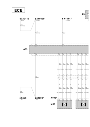
3. Circuit diag ram
3 .1 Circuit diag ram (for ECE ca rs only )........................................................................\
.................. 3-3
3 .2 Circuit diag ram (for U S ca rs only )........................................................................\
.................. ..3-12
3-1


........................................................................\
.................. 3-3
3 .2 Circuit diag ram (for U S c")