2000 AUDI ALLROAD service reset
[x] Cancel search: service resetPage 117 of 306

CONTROLS AND EQUIPMENT---------------------
Instrument cluster
Pos. see page
1 - Engine oil temperature gauge ... 117
2 - Tachometer ...... ........... .. 117
with digital clock and date display 117
3- Warning I ind icator lights ..... .. 122
4 - Engine coolant temperature gauge 118
5- Fuel gauge
119 Pos.
6 · Speedometer
with odometer,
trip odometer display ... .
7 - Vo ltmeter ............ .
8 - Set I check knob for see
page
119
12 0
12 0
Setting the clock . . . . . .
118
Auto -check system ............ 140
Clock and Odometer lighting .... 12 0
Service indicator . . . . . . . . . . . . . . 121 Pos.
see page
9 - Driver information system
Auto-C heck System display . . . . 138
Outside air temperature display .
137
Trip computer display . . . . . . . . 146
Selector lever position display . .
1 07
Radio frequency display ........ 138
Service interval display . . . . . . 121
1 0 -Reset knob for
Trip odometer ......•.. _ ..... .. 120
Service indicator . . . . . . . . . . . . 121
Page 121 of 306

CONTROLS AND
EQUIPMEN T--------------------
Odometer
The odometer indicates the distance driven.
USA models:
Miles
Canada models: Kilometres
On the trip odometer, the last digit indicates
1 /,0 of a mile or 1 00 meters.
Reset knob for trip odometer
To record a distance, reset the trip odome
ter by pressing the knob until the display re
turns to zero -see illustrat ion.
12 0 When
the ignition is off, the display can be
ill umin ated by pressing the test knob for the
Auto-Check System. See page 116, posi
tion 8. The display switches off automati
cally after about 15 seconds.
Also the display will remain illuminated for
abo �t 30 seconds after you open the driv
er's door.
Defect message
If there is a defect in the instrument cluster,
"dEF" will be displayed continuously in the
trip odometer display area. Have this prob
lem corrected as soon as possible by an au
thorized Audi Dealer.
7 - Vo ltmeter
The voltmeter indicates the voltage for the
vehicle's total electrical system, which
should normally be between 12 and
14 volts. If the display drops below 12 volts
when the engine is running, have the power
supply (battery and alternator) checked by
an authorized Audi Dealer. See also
pages 127 and 143.
The voltage may fall below 8 volts while the
engine is being started. 8
- Set I Check knob
Setting the clock ...• ... .
Auto-ch eck system
Odometer lighting .
Service indicator .. 118
14 0
12 0
121
9 - Driver information system
Auto-C heck System display . . . . . ... 138
Outside air temperature display .... 137
Tr ip computer display . . . . . . . . 146
Selector lever position display ....... 1 07
Radio frequency display . . . . . . 138
Service interval display . . . . . . . . . . .
121
10 -Reset knob
Reset knob for trip odometer . .... .. 12 0
Service indicator . . . . . .. . . . . . . 121
Page 122 of 306

Service
Interval Display
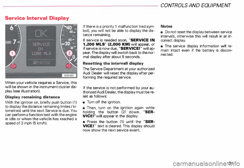
When your vehicle requires a Service, this
will be shown in the instrument cluster dis
play (see illustration).
Display remaining distance
With the ignition on, briefly push button (1)
to display the distance remaining (miles I ki
lometres) until the next Service is due. You
can perform a function test with the engine
in idle or when the vehicle has reached a
speed of 3 mph (5 km/h). If
there is a priority 1 malfunction (red sym
bol), you will not be able to display the dis
tance remaining.
If service is needed soon, "SERVICE IN
1, 200 MLS" (2,000 KM) will appear, or
if service is now due, "SERVICE! " will ap
pear. The display will switch back to the nor
mal display after about 5 seconds.
Resetting the interval! display
The Service Department at your authorized
Audi Dealer will reset the display after per
forming the required service.
If the service is not performed by your au
thorized Audi Dealer, the display must be re
set as follows:
• Turn off the ignition.
• Then, turn on the ignition again while
holding the button (2) down. "SER
VICE!"will appear in the display.
• Press the button (1) until the "SER
VICE !" text is cleared. This display should
now show the next service event. CONT
ROLS AND EQUIPMENT
Notes
• Do not reset the display betwee n service
interv als, otherwise this will result in an in
correct display.
• The service display information will re
main intact even if the battery is discon
nected. 121
Page 131 of 306

CONTROLS AND
EQUIPMENT--------------------
Driver information system
Display
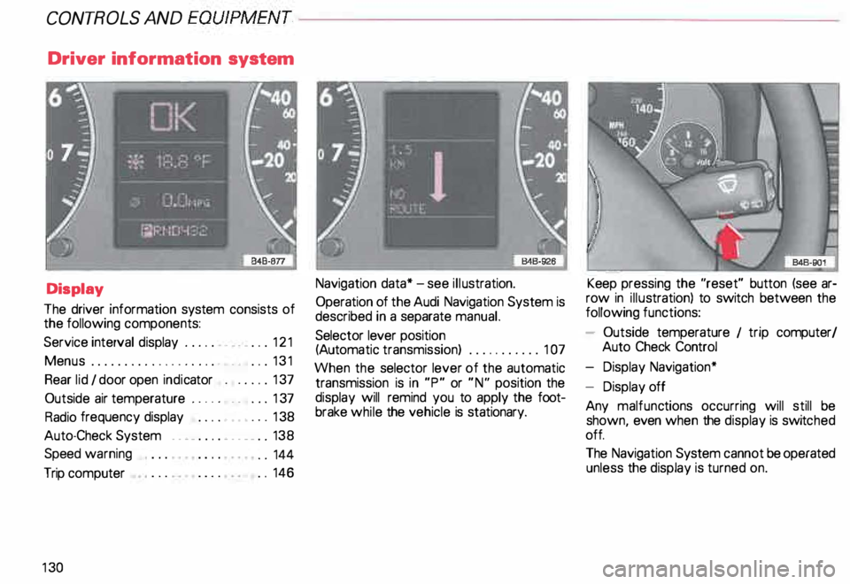
The driver information system consists of
the following components:
Service interval display . . . . . . _. _ ... 121
Menu s................... _ . ... 131
Rear lid I door open indicator _ _ .... 137
Outside air temperature __ . . . _ _ ... 137
Radio frequency display . . . . • .• ___ 138
Auto-Check System ____ .... ____ _ . _ 138
Speed warning
.. 144
Trip computer . .
146
13 0 Navigation
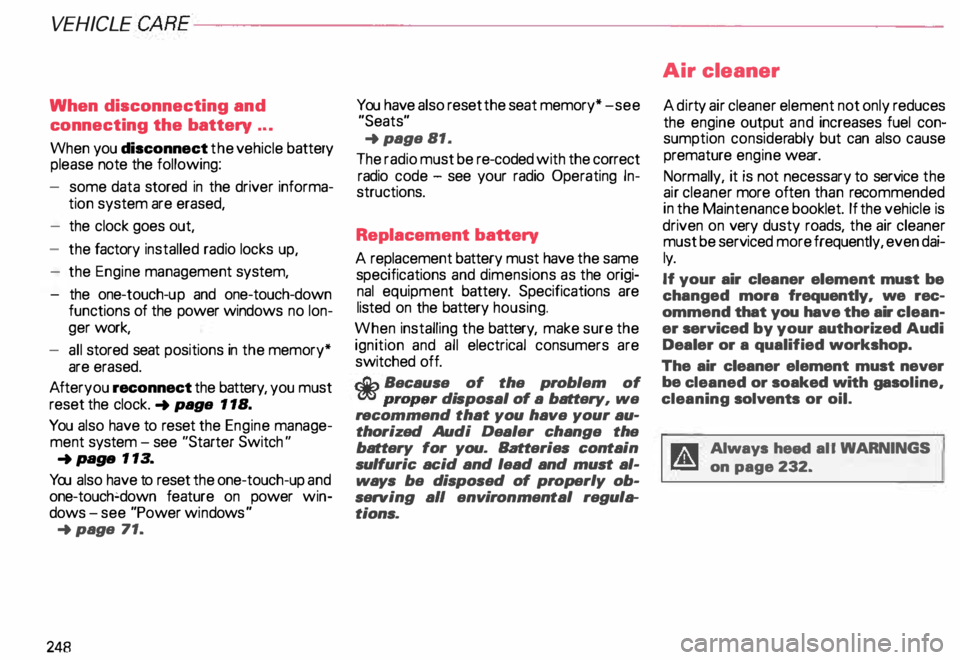
data* -see illustration.
Operation of the Audi Navigation System is
described in a separate manual.
Selector lever position
(Auto matic transmission) ........... 1 07
When the selector lever of the automatic
transmission is in "P" or "N" position the
display will remind you to apply the foot
brake while the vehicle is stationary. Keep
pressing the "reset" button (see ar
row in illus tration) to switch between the
following functions:
- Outside temperature 1 trip computer/
Auto Check Control
- Display Navigation*
- Display off
Any malfunc tions occurring will still be
shown, even when the display is switc hed
off.
The Navigation System cannot be operated
unless the display is turned on.
Page 249 of 306

VEHICLE CA
RE----------------------------------------------------
When disconnecting and
connecting the battery ...
When you disconnect the vehicle battery
please note the following:
- some data stored in the driver informa-
tion system are erased,
- the clock goes out,
- the factory installed radio locks up,
- the Engine management system,
- the one-touch-u p and one-touch-down
functions of the power windows no lon
ger work,
- all stored seat positions in the memory*
are erased.
Af teryou reconnect the battery, you must
reset the clock. � page 118.
You also have to reset the Engine manage
ment system -see "Starter Switch "
�pa ge 113.
You also have to reset the one-touch-up and
one-touch�down feature on power win
dows -see "Power windows "
�p age 71.
248 You
have also reset the seat memory* -see
"Seats"
� page 81.
The radio must be re-coded with the correct
radio code - see your radio Operating In
structions.
Replacement battery
A replacement battery must have the same
specifications and dimensions as the origi
nal equipment battery. Specifications are
listed on the battery housing.
When installing the battery, make sure the
ignition and all electrical consumers are
switched off.
r.Gb. Because of the problem of �proper di
sposal of a battery, we
recommend that you have your au
thorized Audi Dealer change the
battery for you. Batteries contain
sulfuric acid and lead and must al
ways be disp osed of properly ob
serving all environmental regula
tions. Air
cleaner
A dir ty air cleaner element not only reduces
the engine output and increases fuel con
sumption considerably but can also cause
premature engine wear.
Normally, it is not necessary to service the
air cleaner more often than recommended
in the Maintenance booklet. If the vehicle is
driven on very dusty roads, the air cleaner
must be serviced more frequently, even dai
ly.
If your air cleaner element must be
changed mora frequently, we rec
ommend that you have the air clean
er serviced by your authorized Audi
Dealer or a qualified workshop.
The air cleaner element must never
be cleaned or soaked with gasoline,
cleaning solvents or oil.
g Always heed all WARN INGS
t!!3 on page 232.
Page 277 of 306

DO-IT-YOURSELF
SERVICE----------------------
No.
A11 No.
A 11 Automatic
circuit breakers
26 -Rear window defogger,
air recirculation . . . . . . . .
30
27 -Heated steering wheel,
rear window wiper , . . . . . 15
28 -Fuel pump . . . . . . . , . . . . 20
29 - Engine timing . . . . . . . . . .
30
30 -Power roof . . . . . .
. ... 20
31 -Back-up lights, cruise control,
Automatic Transmission,
data link connector for
On Board Diagnostic,
automatic dimmng inside mirror
15
32 -Engine timing . . . . . . . . . . . . . . . . . 20
33 -Ciga rette lighter 15
34 - Engine timing
1l Amps
276 15 35
-Va cant
36 -Front fog lights,
rear fog light ...... .
37 -Radio ........... .
38 - Luggage compartment light, . . .
15
. . ... 20
power locking system . . . . . . . . . . 20
39 -Emergency flasher system ....... 15
40 -Horn . . . . . . . . . . . . . . . . . . . . . . . 25
41 -Anti-lock brake system (ABS) .. .. 25
42 -Electronic Stability Programm .... 25
43 -$-contact (radio) . . . . . . . . . . . . . . 5
44 -Seat heating . ... ... . ... ... ..... 30 The
electric power windows and the elec
tric seat adjusters are protected with circuit
breakers which reset automatically after
the circuit overload has been correcte d.