2000 AUDI ALLROAD reset
[x] Cancel search: resetPage 61 of 306

CONTROLS AND
EQUIPMENT--------------------
Remember- the panic function can be seen
and heard by other motorists and I or per
sons near you.
Use the panic function only if you
are In an emergency situation.
�W ARNING
Do not leave children unattended
in the vehicle especially with ac
cess to the remote control. There
mote control could be used to lock
the doors delaying access to the
children in an emergency.
Resetting the remote control
If your vehicle will not lock using the remote
control . it could be that the code for the con
trol unit and key needs to be reset. This can
occur if you frequently use the remote c �m
trol while standing outside of the effective
range.
60 Resetting
procedure
1 - To synchronize, press button A or but
ton Con the remote control one time.
2 - Then, within one minute, lock or un
lock the driver's door with the master
key.
The system is now functional.
Operating locks using the key
• To lock and unlock the vehicle from
the outside, turn the key in the lock of the
driver's door or the rear lid.
Yo u can also lock and unlock the vehicle by
turning the key in the re ar lid lock. See
page 63.
• Turn the key one time only to unlock
(A) either the driver's door or respectively
the rear lid.
• Turn the key two times to unlock all ve
hicle doors and the rear lid. Convenience
close I open feature
You can also close any open windows and
1 or the power roof* when you lock your car
with the key.
Insert the key into the lock of the driver's
door, turn it to the lock position (B) and hold
until the wind ows and sunroof are com
pletely closed. The automatic close function
will stop immediately if the key is released.
Always make sure the windows are
not obstructed.
To open all window s: insert your key into the
lock of the dr iver's door, turn it to the open
position (A) and then hold it in this position.
Page 117 of 306

CONTROLS AND EQUIPMENT---------------------
Instrument cluster
Pos. see page
1 - Engine oil temperature gauge ... 117
2 - Tachometer ...... ........... .. 117
with digital clock and date display 117
3- Warning I ind icator lights ..... .. 122
4 - Engine coolant temperature gauge 118
5- Fuel gauge
119 Pos.
6 · Speedometer
with odometer,
trip odometer display ... .
7 - Vo ltmeter ............ .
8 - Set I check knob for see
page
119
12 0
12 0
Setting the clock . . . . . .
118
Auto -check system ............ 140
Clock and Odometer lighting .... 12 0
Service indicator . . . . . . . . . . . . . . 121 Pos.
see page
9 - Driver information system
Auto-C heck System display . . . . 138
Outside air temperature display .
137
Trip computer display . . . . . . . . 146
Selector lever position display . .
1 07
Radio frequency display ........ 138
Service interval display . . . . . . 121
1 0 -Reset knob for
Trip odometer ......•.. _ ..... .. 120
Service indicator . . . . . . . . . . . . 121
Page 121 of 306

CONTROLS AND
EQUIPMEN T--------------------
Odometer
The odometer indicates the distance driven.
USA models:
Miles
Canada models: Kilometres
On the trip odometer, the last digit indicates
1 /,0 of a mile or 1 00 meters.
Reset knob for trip odometer
To record a distance, reset the trip odome
ter by pressing the knob until the display re
turns to zero -see illustrat ion.
12 0 When
the ignition is off, the display can be
ill umin ated by pressing the test knob for the
Auto-Check System. See page 116, posi
tion 8. The display switches off automati
cally after about 15 seconds.
Also the display will remain illuminated for
abo �t 30 seconds after you open the driv
er's door.
Defect message
If there is a defect in the instrument cluster,
"dEF" will be displayed continuously in the
trip odometer display area. Have this prob
lem corrected as soon as possible by an au
thorized Audi Dealer.
7 - Vo ltmeter
The voltmeter indicates the voltage for the
vehicle's total electrical system, which
should normally be between 12 and
14 volts. If the display drops below 12 volts
when the engine is running, have the power
supply (battery and alternator) checked by
an authorized Audi Dealer. See also
pages 127 and 143.
The voltage may fall below 8 volts while the
engine is being started. 8
- Set I Check knob
Setting the clock ...• ... .
Auto-ch eck system
Odometer lighting .
Service indicator .. 118
14 0
12 0
121
9 - Driver information system
Auto-C heck System display . . . . . ... 138
Outside air temperature display .... 137
Tr ip computer display . . . . . . . . 146
Selector lever position display ....... 1 07
Radio frequency display . . . . . . 138
Service interval display . . . . . . . . . . .
121
10 -Reset knob
Reset knob for trip odometer . .... .. 12 0
Service indicator . . . . . .. . . . . . . 121
Page 122 of 306

Service
Interval Display
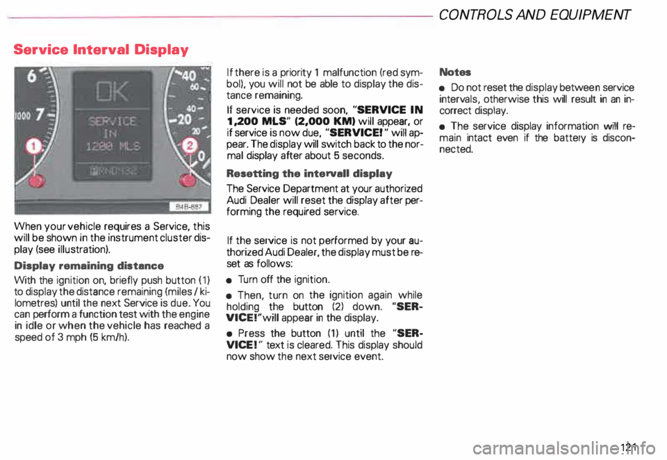
When your vehicle requires a Service, this
will be shown in the instrument cluster dis
play (see illustration).
Display remaining distance
With the ignition on, briefly push button (1)
to display the distance remaining (miles I ki
lometres) until the next Service is due. You
can perform a function test with the engine
in idle or when the vehicle has reached a
speed of 3 mph (5 km/h). If
there is a priority 1 malfunction (red sym
bol), you will not be able to display the dis
tance remaining.
If service is needed soon, "SERVICE IN
1, 200 MLS" (2,000 KM) will appear, or
if service is now due, "SERVICE! " will ap
pear. The display will switch back to the nor
mal display after about 5 seconds.
Resetting the interval! display
The Service Department at your authorized
Audi Dealer will reset the display after per
forming the required service.
If the service is not performed by your au
thorized Audi Dealer, the display must be re
set as follows:
• Turn off the ignition.
• Then, turn on the ignition again while
holding the button (2) down. "SER
VICE!"will appear in the display.
• Press the button (1) until the "SER
VICE !" text is cleared. This display should
now show the next service event. CONT
ROLS AND EQUIPMENT
Notes
• Do not reset the display betwee n service
interv als, otherwise this will result in an in
correct display.
• The service display information will re
main intact even if the battery is discon
nected. 121
Page 131 of 306

CONTROLS AND
EQUIPMENT--------------------
Driver information system
Display
The driver information system consists of
the following components:
Service interval display . . . . . . _. _ ... 121
Menu s................... _ . ... 131
Rear lid I door open indicator _ _ .... 137
Outside air temperature __ . . . _ _ ... 137
Radio frequency display . . . . • .• ___ 138
Auto-Check System ____ .... ____ _ . _ 138
Speed warning
.. 144
Trip computer . .
146
13 0 Navigation
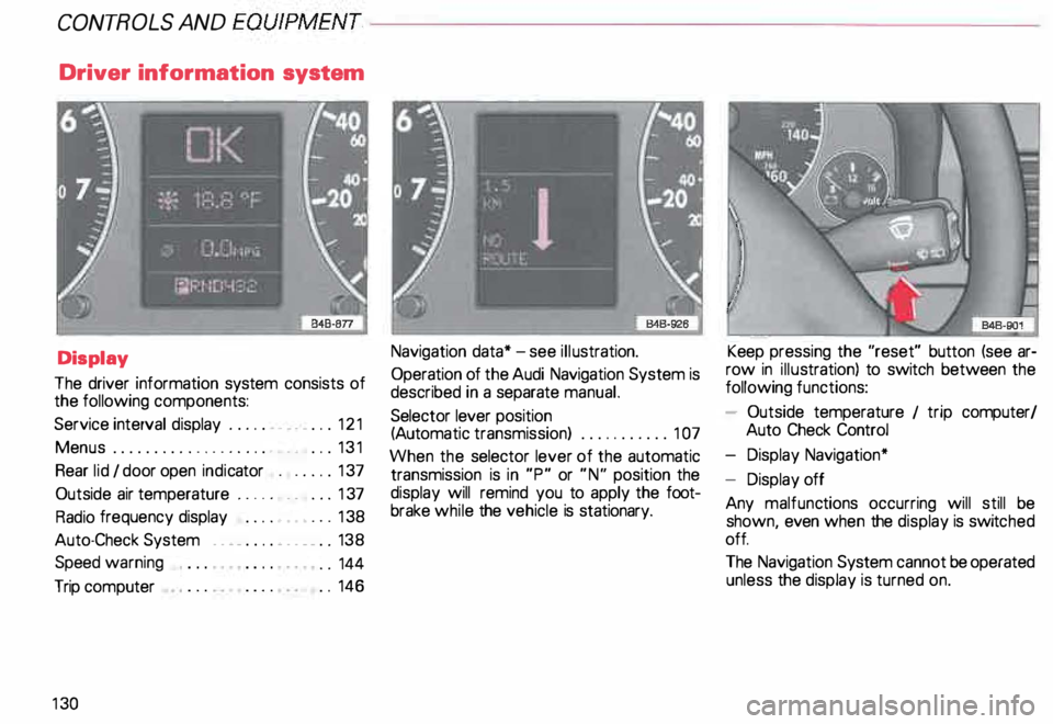
data* -see illustration.
Operation of the Audi Navigation System is
described in a separate manual.
Selector lever position
(Auto matic transmission) ........... 1 07
When the selector lever of the automatic
transmission is in "P" or "N" position the
display will remind you to apply the foot
brake while the vehicle is stationary. Keep
pressing the "reset" button (see ar
row in illus tration) to switch between the
following functions:
- Outside temperature 1 trip computer/
Auto Check Control
- Display Navigation*
- Display off
Any malfunc tions occurring will still be
shown, even when the display is switc hed
off.
The Navigation System cannot be operated
unless the display is turned on.
Page 147 of 306

CONT
ROLS AND EQUIPMENT---------------------
Trip computer
This feature generates much helpful infor
mation by simple touch control. For the driv
er's convenience, the computer's memory
display window is integrated in the instru
ment cluster.
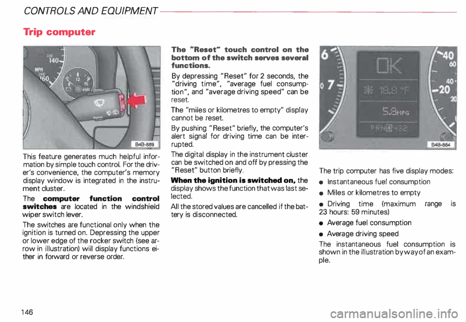
The computer function control
switches are located in the windshield
wiper switch lever.
The switches are functional only when the
ignition is turned on. Depressing the upper
or lower edge of the rocker switch (see ar
row in illustration) will display functions ei
ther in forward or reverse order.
14 6 The
"Reset" touch control on the
bottom of the switch serves several
functions.
By depressing "Reset" for 2 seconds, the
"d riving time", "average fuel consump
ti on", and "average driving speed" can be
reset.
The "miles or kilometres to empty" display
cannot be reset.
By pushing "Reset" briefly, the computer's
alert signal for driving time can be inter
rupted.
The digital display in the instrument cluster
can be switched on and off by pressing the
"R eset" button briefly.
When the ignition is switched on, the
display shows the function that was last se
lected.
All the stored values are cancelled if the bat
tery is disconne cted. The
trip computer has five display modes:
• Instantaneous fuel consumption
• Miles or kilometres to empty
• Driving time (maximum range is
23 hours: 59 minutes)
• Average fuel consump tion
• Avera ge driving speed
The instantaneous fuel consumption is
shown in the illustration by way of an exam
ple.
Page 148 of 306

---------------------CONTROLS AND
EQUIPMEN T
USA models:
computer calculations are displayed in the
USA measuring system
Canada models:
computer calculations are displayed in the
metric system
1/1 00 km -Instantaneous
(MPG) fuel
consumption
Fuel consumed instantaneously IS mea
sured every 1 00 feet or 30 meters and dis
played in units of miles per gallon (MPG) or
liters per 100 kilometres (1/1 OOkm). When
this function is selected right after engine
start -up, the display will show the average
fuel consump tion figure for the first 100
feet or 30 meters. When the vehicle is sta
tionar y, the last unit measured will be dis
played.
km -Kilome tres or miles to
{Mi) empty
The displa yed information (indicated in
stages of 5 miles or 1 0 kilometres) is based
on the average fuel consumption computed
during the last 20 miles or 30 kilometers. This
feature informs the driver how many
miles or kilometres of normal and smooth
driving can be covered with whatever
amount of fuel remains in the tank. Fuel
economy is the result of good driving habits.
h Driving time
Driving time elapsed will remain in storage,
even pfter the ignition is turned off. Further
driving time will be added automat ically af
ter engine restart. Maximum storage and
display range is 23 hours: 59 minutes. To
keep track of driving time between points,
depress "Reset" for zero.
Driving time alert
While driving, the computer will automati
cally switch to the "driving time" display ev
ery two hours. The indicator "2:00" (or
"4:00", "6:00", "8:00" etc.) will blink in the
display window to alert the driver to take a
break. The blinker can be turned off briefly
by pushing "Reset'' or either side of the
switch. If the
ignition is off more than ten minu tes,
the driving time alert counter will automati
cally start again from zero. If the ignition is
off less than ten minutes, the display will
blink again every two hours.
0 I (MPG) -Ave rage fuel
100 km
consumption
The display will show the computed aver
age since the last "Reset". When the igni
tion is turned off, the computed average re
mains in storage. When driving is resumed,
the computation continues automatically.
To delete stored data, push "Reset".
0 km/h -Average driving
(MPH) speed
The display will show the computed aver
age of driving speed variations since the last
"R eset". When the ignition is turned off,
the computed average remains in stora ge.
When driving is resumed, the computation
continues automatically. To delete stored
data, push "Reset"
147
Page 151 of 306

CONTROLS AND
EQUIPMENT--------------------
1 and 4-Electrically heated ... 8
seats• utJ
The heating elements in both seats can be
turned on and regulated separately with the
two thumb wheel switches.
With the ignition on, the seat cushion and
backrest of the front seats can be heated
electrically.
15 0 1
- Use this thumb wheel switch to activate
and regulate the heating elements in the
driver's seat.
4- Use this thumbwheel switch to activate
and regulate the heating elements in the
front passenger's seat.
From position 0, roll thumbwheel upward to
activate the heating elements.
Select the desired temperature setting be
tween positions 1-6. When the heating ele
ments are activated, the numbers on the
thumb wheel will light up.
The steering wheel heating* is
swit ched on automatically when the seat
heating is switched on. The temperature.
however, remains at a constant preset level
and cannot be regulated with the thumb
wheel (1).
Note
To prevent possible damage to the heating
elements, do not kneel on the seats or in
any other way apply a heavy load to relative
ly small areas of the seat. The
heating elements* for the left and right
seating positions of the rear seat bench are
switched on and off and regulated by the
thumbwheel in the center console:
a - left
b- right
The rear seat heating* only operates when
a sensor registers the weight of the occu
pant on the seat.
Select the desired temperature setting be
tween positions 1-6. When the heating ele
ments are activated, the numb ers on the
thumbwheel will light up.