2000 AUDI ALLROAD trip computer
[x] Cancel search: trip computerPage 117 of 306

CONTROLS AND EQUIPMENT---------------------
Instrument cluster
Pos. see page
1 - Engine oil temperature gauge ... 117
2 - Tachometer ...... ........... .. 117
with digital clock and date display 117
3- Warning I ind icator lights ..... .. 122
4 - Engine coolant temperature gauge 118
5- Fuel gauge
119 Pos.
6 · Speedometer
with odometer,
trip odometer display ... .
7 - Vo ltmeter ............ .
8 - Set I check knob for see
page
119
12 0
12 0
Setting the clock . . . . . .
118
Auto -check system ............ 140
Clock and Odometer lighting .... 12 0
Service indicator . . . . . . . . . . . . . . 121 Pos.
see page
9 - Driver information system
Auto-C heck System display . . . . 138
Outside air temperature display .
137
Trip computer display . . . . . . . . 146
Selector lever position display . .
1 07
Radio frequency display ........ 138
Service interval display . . . . . . 121
1 0 -Reset knob for
Trip odometer ......•.. _ ..... .. 120
Service indicator . . . . . . . . . . . . 121
Page 121 of 306

CONTROLS AND
EQUIPMEN T--------------------
Odometer
The odometer indicates the distance driven.
USA models:
Miles
Canada models: Kilometres
On the trip odometer, the last digit indicates
1 /,0 of a mile or 1 00 meters.
Reset knob for trip odometer
To record a distance, reset the trip odome
ter by pressing the knob until the display re
turns to zero -see illustrat ion.
12 0 When
the ignition is off, the display can be
ill umin ated by pressing the test knob for the
Auto-Check System. See page 116, posi
tion 8. The display switches off automati
cally after about 15 seconds.
Also the display will remain illuminated for
abo �t 30 seconds after you open the driv
er's door.
Defect message
If there is a defect in the instrument cluster,
"dEF" will be displayed continuously in the
trip odometer display area. Have this prob
lem corrected as soon as possible by an au
thorized Audi Dealer.
7 - Vo ltmeter
The voltmeter indicates the voltage for the
vehicle's total electrical system, which
should normally be between 12 and
14 volts. If the display drops below 12 volts
when the engine is running, have the power
supply (battery and alternator) checked by
an authorized Audi Dealer. See also
pages 127 and 143.
The voltage may fall below 8 volts while the
engine is being started. 8
- Set I Check knob
Setting the clock ...• ... .
Auto-ch eck system
Odometer lighting .
Service indicator .. 118
14 0
12 0
121
9 - Driver information system
Auto-C heck System display . . . . . ... 138
Outside air temperature display .... 137
Tr ip computer display . . . . . . . . 146
Selector lever position display ....... 1 07
Radio frequency display . . . . . . 138
Service interval display . . . . . . . . . . .
121
10 -Reset knob
Reset knob for trip odometer . .... .. 12 0
Service indicator . . . . . .. . . . . . . 121
Page 131 of 306

CONTROLS AND
EQUIPMENT--------------------
Driver information system
Display
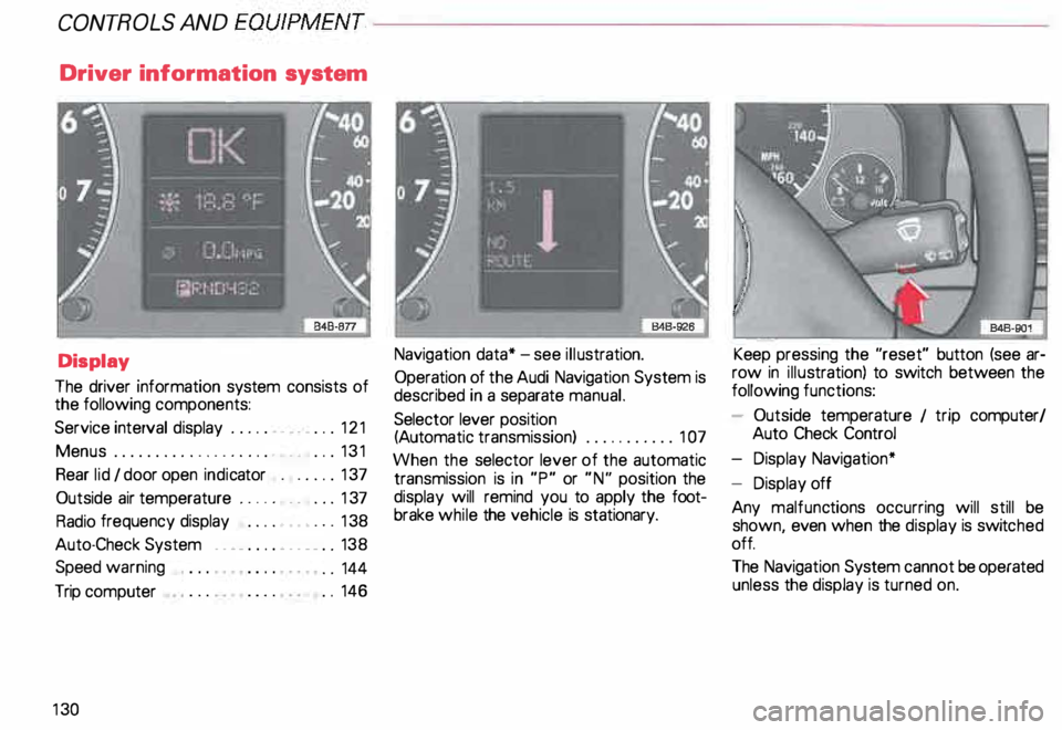
The driver information system consists of
the following components:
Service interval display . . . . . . _. _ ... 121
Menu s................... _ . ... 131
Rear lid I door open indicator _ _ .... 137
Outside air temperature __ . . . _ _ ... 137
Radio frequency display . . . . • .• ___ 138
Auto-Check System ____ .... ____ _ . _ 138
Speed warning
.. 144
Trip computer . .
146
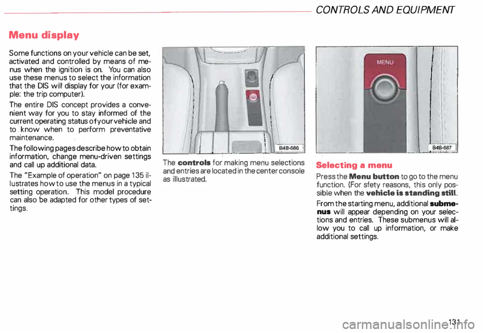
13 0 Navigation
data* -see illustration.
Operation of the Audi Navigation System is
described in a separate manual.
Selector lever position
(Auto matic transmission) ........... 1 07
When the selector lever of the automatic
transmission is in "P" or "N" position the
display will remind you to apply the foot
brake while the vehicle is stationary. Keep
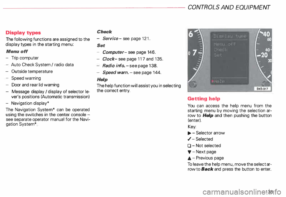
pressing the "reset" button (see ar
row in illus tration) to switch between the
following functions:
- Outside temperature 1 trip computer/
Auto Check Control
- Display Navigation*
- Display off
Any malfunc tions occurring will still be
shown, even when the display is switc hed
off.
The Navigation System cannot be operated
unless the display is turned on.
Page 132 of 306

Menu
display
Some functions on your vehicle can be set,
activated and controlled by means of me
nus when the ignition is on. You can also
use these menus to select the information
that the DIS will display for your (for exam
ple: the trip computer).
The entire DIS concept provides a conve
nient way for you to stay informed of the
current operating status of your vehicle and
to ·, know when to perform preventative
maintenance.
The following pages describe how to obtain
information, change menu-driven settings
and call up additional data.
The "Example of operation" on page 135 il
lu strates how to use the menus in a typical
setti ng operati on. This model procedure
can also be adapted for other types of set
tings. The
controls for making menu selections
and entries are located in the center console
as illus trated. CONT
ROLS AND EQUIP MENT
S�lecting a menu
Press the Menu button to go to the menu
function. (For sfety reasons, this only pos
sible when the vehicle is standing still.
From the starting menu, additional subme
nus will appear depending on your selec
tions and entries. These submenus will al
low you to call up information, or make
additional settings.
131
Page 134 of 306

--------------------CONTROLS
AND EQUIPMENT
Display types
The following functions are assigned to the
display types in the starting menu:
Menu off
- Trip computer
- Auto Check System I radio data
- Outside temperature
- Speed warning
- Door and rear lid waming
- Message display I display of selector le-
ver's positions (Automatic transmission)
- Navigation display*
The Navigation System* can be operated
using the switches in the center console -
see separate operator manual for the Navi
gation System* Check
- Service -see page 121 .
Set
- Comput er-see page 146.
Cl ock- see page 117 and 135.
Radio info. -see page 138.
- Speed warn. -see page 144.
Help
The help function will assist you in selecting
the correct entry.
Getting help
You can access the help menu from the
starting menu by moving the selection ar
row to Help and then pushing the button
(enter).
Key:
.., . - Selector arrow
,/- Selected
0 - Not selected
'f' -Next page
.&. -.Previous page
To leave the help menu, move the select ar
row to Back and press the button to enter.
133
Page 146 of 306

Cancelling speed limit
Press the test button for at least 1 second
when the yehicle is moving at a speed
above 3 miles (5 km/h). The display will
show the warning symbol crossed through
to confirm that the speed limit has been
cleared.
Speed warning 2
82
When the ignition is switc hed off, the driver
can store a permanent speed limit
warning in the unit. The
warning is shown in the display as de
scribed. The warning symbol only goes out
once the road speed has fallen below the
stored value again.
We recommend to store this speed limit
v:' arning if you wish to be reminded of a par
ticular speed limit in addition to speed limit
warning 1. (For instance when driving in
countries with general speed limits or if a
particular speed should not be exceeded
when winter tires are fitted, etc.)
Selecting speed limit
• Press the test button briefly with the
ignition switched off. The mileage re
corder display will then light up.
• Press the test button again and hold for
at least 2 seconds. The speed limit currently
set appears in the disp lay.
• To change the speed limit, press the top
or bottom of the function selector switch for
the trip computer (see arrow illustration).
The speed limit displayed will then increase
or decrease by 6 miles (1 0 km/h ) at a time. CONT
ROLS AND EQUIPMENT
• A few seconds after the button is re
leased, the display lighting goes out again.
Cancelling speed limit
P _ress the .test button briefly with the igni
tion sw1tched off; the display will light
up. Press the test button again for at least
2 seconds: the display will show the .speed
limit currently set. Now press and hold the
"R eset" button for the trip computer until
the crossed-out warning symbol appears.
145
Page 147 of 306

CONT
ROLS AND EQUIPMENT---------------------
Trip computer
This feature generates much helpful infor
mation by simple touch control. For the driv
er's convenience, the computer's memory
display window is integrated in the instru
ment cluster.
The computer function control
switches are located in the windshield
wiper switch lever.
The switches are functional only when the
ignition is turned on. Depressing the upper
or lower edge of the rocker switch (see ar
row in illustration) will display functions ei
ther in forward or reverse order.
14 6 The
"Reset" touch control on the
bottom of the switch serves several
functions.
By depressing "Reset" for 2 seconds, the
"d riving time", "average fuel consump
ti on", and "average driving speed" can be
reset.
The "miles or kilometres to empty" display
cannot be reset.
By pushing "Reset" briefly, the computer's
alert signal for driving time can be inter
rupted.
The digital display in the instrument cluster
can be switched on and off by pressing the
"R eset" button briefly.
When the ignition is switched on, the
display shows the function that was last se
lected.
All the stored values are cancelled if the bat
tery is disconne cted. The
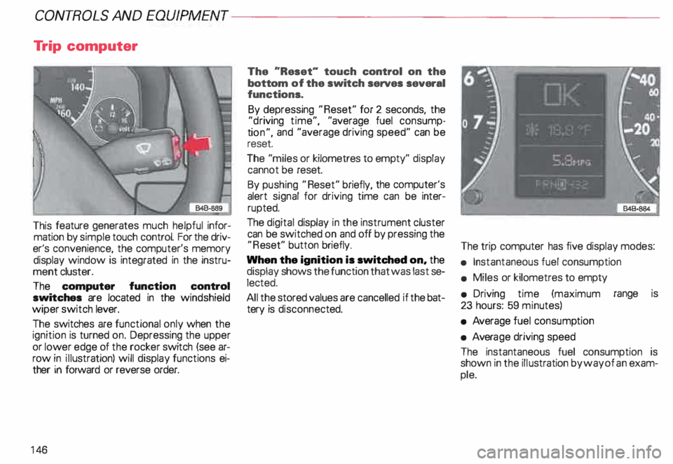
trip computer has five display modes:
• Instantaneous fuel consumption
• Miles or kilometres to empty
• Driving time (maximum range is
23 hours: 59 minutes)
• Average fuel consump tion
• Avera ge driving speed
The instantaneous fuel consumption is
shown in the illustration by way of an exam
ple.