2000 AUDI ALLROAD set clock
[x] Cancel search: set clockPage 117 of 306

CONTROLS AND EQUIPMENT---------------------
Instrument cluster
Pos. see page
1 - Engine oil temperature gauge ... 117
2 - Tachometer ...... ........... .. 117
with digital clock and date display 117
3- Warning I ind icator lights ..... .. 122
4 - Engine coolant temperature gauge 118
5- Fuel gauge
119 Pos.
6 · Speedometer
with odometer,
trip odometer display ... .
7 - Vo ltmeter ............ .
8 - Set I check knob for see
page
119
12 0
12 0
Setting the clock . . . . . .
118
Auto -check system ............ 140
Clock and Odometer lighting .... 12 0
Service indicator . . . . . . . . . . . . . . 121 Pos.
see page
9 - Driver information system
Auto-C heck System display . . . . 138
Outside air temperature display .
137
Trip computer display . . . . . . . . 146
Selector lever position display . .
1 07
Radio frequency display ........ 138
Service interval display . . . . . . 121
1 0 -Reset knob for
Trip odometer ......•.. _ ..... .. 120
Service indicator . . . . . . . . . . . . 121
Page 118 of 306

The illustration on previous page shows the
arrangement of the instrument cluster in a
U.S. vehicle.
1 - Engine oil temperature
gauge �
Of (C)
Engine oil temperature ranges from 150 OF
(60 °C) to 350 °F (180 °C). With the needle
around 150 °F (60 °C), do not accelerate un
der full load.
If the needle moves into the upper zone in
excepti onal cases, reduce your speed. The
needle should then return to the normal
zone.
If the needle stays in upper zone, stop the
vehicle, switch off the engine and check the
oil leve l. If the oil level is correct and the oil
pressure warning light does not flash when
the engine is started, you can drive to the
next authorized Audi Dealer but do·not run
engine at high speeds. 2
- Ta chometer with clock
Ta chometer
The red area at the end of the scale indi
cates maximum permissible engine rpm
(rev olutions per minute) for all gears after
the break-in period. Before reaching this
area, the next higher gear or selector lever
position "D" should be selected or the foot
eased off the accelerator pedal.
r.Gb Upshifting early saves fuel and
1!/!:i reduces engine noise.
Shift to the next lower gear when engine
rpm drops below 1,500 rpm. CONT
ROLS AND EQUIPMENT
Digital clock with date display
The clock and date are located in the
tachometer dial. Adjusting the clock I date:
see next page.
When the ignition is off the clock I date dis
play can be illuminated by pressing the set
butt on. See illustration above.
117
Page 119 of 306

CONTROLS AND
EQUIPMENT-----------------------------------------
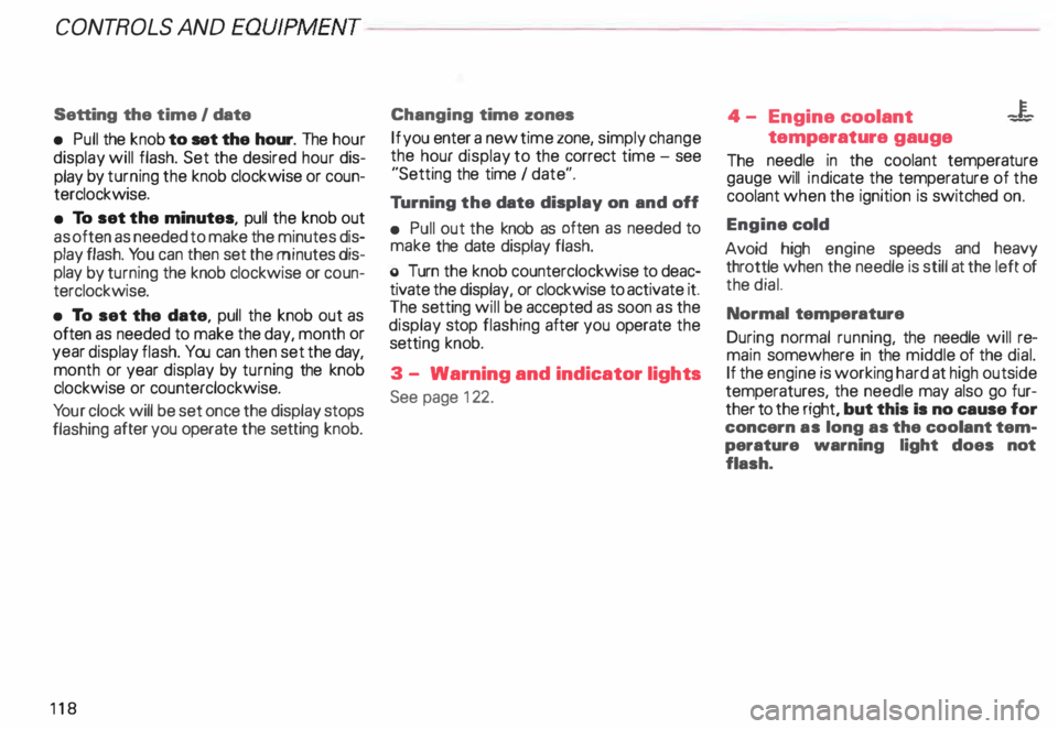
Setting the time I date
• Pull the knob to set the hour. The hour
display will flash. Set the desired hour dis
play by turning the knob clockwise or coun
terclockwise.
• To set the minutes, pull the knob out
as often as needed to make the minutes dis
play flash. You can then set the minutes dis
play by turning the knob clockwise or coun
terclockwise.
• To set the date, pull the knob out as
often as needed to make the day, month or
year display flash. You can then set the day,
month or year display by turning the knob
clockwise or counterclockwise.
Yo ur clock will be set once the display stops
flashing after you operate the setting knob.
118 Changing
time zones
If you enter a new time zone, simply change
the hour display to the correct time -see
"Setting the time I date".
Tu rning the date display on and off
• Pull out the knob as often as needed to
make the date display flash.
o Turn the knob counterclockwise to deac
tivate the display, or clockwise to activate it.
The setting will be accepted as soon as the
display stop flashing after you operate the
setti ng knob.
3 - Warning and indicator lights
See page 122. 4
- Engine coolant -¥
-
temperature gauge
The needle in the coolant temperature
gauge will indicate the temperature of the
coolant when the ignition is switched on.
Engine cold
Avoid high engine speeds and heavy
throttle when the needle is still at the left of
the dial.
Normal temperature
During normal running, the needle will re
main somewhere in the middle of the dial.
If the engine is working hard at high outside
temperatures, the needle may also go fur
ther to the right, but this Is no cause for
concern as long as the coolant tem
perature warning light does not
flash.
Page 121 of 306

CONTROLS AND
EQUIPMEN T--------------------
Odometer
The odometer indicates the distance driven.
USA models:
Miles
Canada models: Kilometres
On the trip odometer, the last digit indicates
1 /,0 of a mile or 1 00 meters.
Reset knob for trip odometer
To record a distance, reset the trip odome
ter by pressing the knob until the display re
turns to zero -see illustrat ion.
12 0 When
the ignition is off, the display can be
ill umin ated by pressing the test knob for the
Auto-Check System. See page 116, posi
tion 8. The display switches off automati
cally after about 15 seconds.
Also the display will remain illuminated for
abo �t 30 seconds after you open the driv
er's door.
Defect message
If there is a defect in the instrument cluster,
"dEF" will be displayed continuously in the
trip odometer display area. Have this prob
lem corrected as soon as possible by an au
thorized Audi Dealer.
7 - Vo ltmeter
The voltmeter indicates the voltage for the
vehicle's total electrical system, which
should normally be between 12 and
14 volts. If the display drops below 12 volts
when the engine is running, have the power
supply (battery and alternator) checked by
an authorized Audi Dealer. See also
pages 127 and 143.
The voltage may fall below 8 volts while the
engine is being started. 8
- Set I Check knob
Setting the clock ...• ... .
Auto-ch eck system
Odometer lighting .
Service indicator .. 118
14 0
12 0
121
9 - Driver information system
Auto-C heck System display . . . . . ... 138
Outside air temperature display .... 137
Tr ip computer display . . . . . . . . 146
Selector lever position display ....... 1 07
Radio frequency display . . . . . . 138
Service interval display . . . . . . . . . . .
121
10 -Reset knob
Reset knob for trip odometer . .... .. 12 0
Service indicator . . . . . .. . . . . . . 121
Page 136 of 306

Go
back to a higher menu level
After obtaining information or making a set
ting, if you wish to return to the next higher
menu level, rotate the button to move the
selection arrow to Back and then press the
butt on. Example
of operation
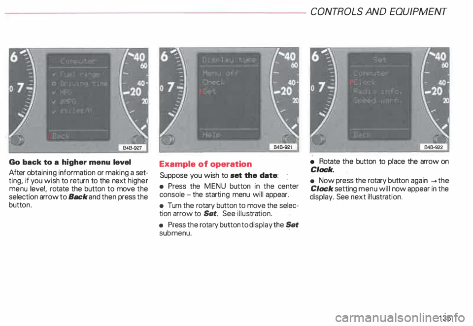
Suppose you wish to set the date:
• Press the MENU button in the center
console -the starti ng menu will appear.
• Turn the rotary button to move the selec
tion arrow to Set. See illustra tion.
• Press the rota ry button to display the Set
submenu. · CONT
ROLS AND EQUIPMENT
• Rotate the button to place the arrow on
Clock.
• Now press the rotary button again __.the
Clock setting menu will now appear in the
display. See next illustra tion.
135
Page 137 of 306

CONT
ROLS AND EQUIPMENT---------------------
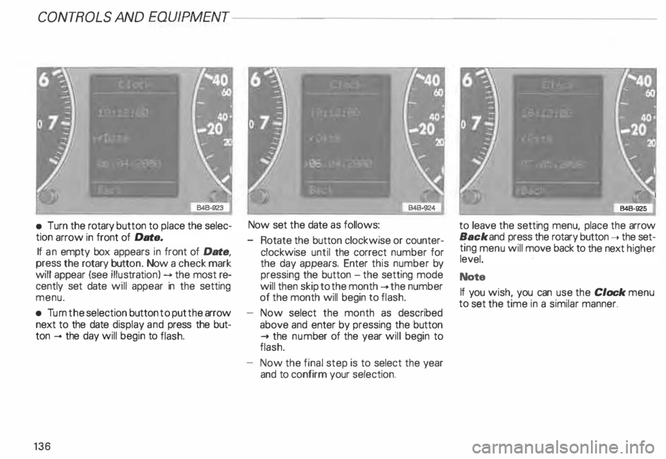
•
Turn the rotary button to place the selec
tion arrow in front of Date.
If an empty box appears in front of Date,
press the rotary button. Now a check mark
will appear (see illustrati on) --> the most re
cently set date will appear in the setting
menu.
• Turn the selection button to put the arrow
next to the date display and press the but
ton -+ the day will begin to flash.
136 Now set
the date as follows:
- Rotate the button clockwise or counter
clockwise until the correct number for
the day appears. Enter this number by
pressing the button -the setting mode
will then skip to the month -+ the number
of the month will begin to flash.
Now select the month as described
above and enter by pressing the button
..... the num ber of the year will begin to
flash.
Now the final step is to select the year
and to confirm your selection. to
leave the setting menu, place the arrow
Back and press the rotary button ..... the set�
ting menu will move back to the next higher
level.
Note
If you wish, you can use the Clock menu
to set the time in a similar manner.
Page 249 of 306

VEHICLE CA
RE----------------------------------------------------
When disconnecting and
connecting the battery ...
When you disconnect the vehicle battery
please note the following:
- some data stored in the driver informa-
tion system are erased,
- the clock goes out,
- the factory installed radio locks up,
- the Engine management system,
- the one-touch-u p and one-touch-down
functions of the power windows no lon
ger work,
- all stored seat positions in the memory*
are erased.
Af teryou reconnect the battery, you must
reset the clock. � page 118.
You also have to reset the Engine manage
ment system -see "Starter Switch "
�pa ge 113.
You also have to reset the one-touch-up and
one-touch�down feature on power win
dows -see "Power windows "
�p age 71.
248 You
have also reset the seat memory* -see
"Seats"
� page 81.
The radio must be re-coded with the correct
radio code - see your radio Operating In
structions.
Replacement battery
A replacement battery must have the same
specifications and dimensions as the origi
nal equipment battery. Specifications are
listed on the battery housing.
When installing the battery, make sure the
ignition and all electrical consumers are
switched off.
r.Gb. Because of the problem of �proper di
sposal of a battery, we
recommend that you have your au
thorized Audi Dealer change the
battery for you. Batteries contain
sulfuric acid and lead and must al
ways be disp osed of properly ob
serving all environmental regula
tions. Air
cleaner
A dir ty air cleaner element not only reduces
the engine output and increases fuel con
sumption considerably but can also cause
premature engine wear.
Normally, it is not necessary to service the
air cleaner more often than recommended
in the Maintenance booklet. If the vehicle is
driven on very dusty roads, the air cleaner
must be serviced more frequently, even dai
ly.
If your air cleaner element must be
changed mora frequently, we rec
ommend that you have the air clean
er serviced by your authorized Audi
Dealer or a qualified workshop.
The air cleaner element must never
be cleaned or soaked with gasoline,
cleaning solvents or oil.
g Always heed all WARN INGS
t!!3 on page 232.
Page 273 of 306

DO-IT-Y
OURSELF SERVICE----------------------
Step
7
Inflating the deflated full size
spare tire
• Remove the dust cap from the valve (1 l
by unscrewing it.
• Take the pressure compressor hose out
of the case, and screw the coupling nut se
curely onto the valve.
• Insert the compressor· connector in to
the socket located on the side of the lug
gage compartment or inset it ino the ciga
rette lighter socket -see page 181.
272 •
Turn on the compressor. The required tire
pressure wil be reached within a few min
utes. Use a pressure gauge to check the tire
pressure. Never operate the compressor
for longer than 5 minutes.
Note
Yo u'll find adhesive labels on the deflated
full size spare tire containing i nstn .1ctions for
using the tire as well as information on the
specified tire pressure.
Step S
• Un screw the pressure hose from the val
ve and screw the dust cap back on.
• To lower the vehicle, turn the handle
counter-clockwise until the jack is fully re
leased. Remove jack.
• Then go crosswise from one bolt to
another tightening them firmly.
• If necessary, press the hubcap back onto
the hub of the spare wheel. Step
9
• Slip the plastic cover over the wheel con
taining the flat tire. Then stow this wheel in
the luggage comopartment and secure it so
that it does not shift.
• Carefully observe the points on
page 288 when using the deflated
full size spare tire.
Notes
• The hex socket in the screwdriver can be
used to make it easier to handle the wheel
bolts. To do this, pull out the revers ible bla-
de. ·
Never use this plastic tool to loosen
or tighten the wheel bolts.
After you change a tire:
• Deactivating the jack moda -see
page 268.
• Use a torque wrench to check the
wheel bolt tightening torque as
soon as possible. With alloy wheels
and a deflated full size spare tire, the
torque should be 88.5 ft-lb (120
Nm).