Page 89 of 381
3 - 20
CHK
ADJCHECKING THE SPARK PLUGS/
MEASURING THE COMPRESSION PRESSURE
5. Check:
• electrodes 1
Damage/wear ® Replace the spark
plug.
• insulator 2
Abnormal color ® Replace the spark
plug.
Normal color is medium-to-light tan.
6. Clean:
• spark plug
(with a spark plug cleaner or wire
brush)
7. Measure:
• spark plug gap a
(with a wire gauge)
Out of specification ® Regap.
8. Install:
• spark plug
NOTE:
Before installing the spark plug, clean
the spark plug and gasket surface.
Spark plug gap
0.7 ~ 0.8 mm (0.028 ~ 0.031 in)
T R..13 Nm (1.3 m · kg, 9.4 ft · lb)
EB303060
MEASURING THE COMPRESSION
PRESSURE
The following procedure applies to all of
the cylinders.
NOTE:
Insufficient compression pressure will
result in a loss of performance.
1. Measure:
• valve clearance
Out of specification ® Adjust.
Refer to “ADJUSTING THE VALVE
CLEARANCE”.
2. Start the engine, warm it up for several
minutes, and then stop it.
Page 94 of 381

10.Install:
• engine oil filler cap
11.Start the engine, warm it up for seve")
3 - 25
CHK
ADJ
CHANGING THE ENGINE OIL
9. Fill:
• crankcase
(with the specified amount of the rec-
ommended engine oil)
10.Install:
• engine oil filler cap
11.Start the engine, warm it up for several
minutes, and then turn it off.
12.Check:
• engine
(for engine oil leaks)
13.Check:
• engine oil level
Refer to “CHECKING THE ENGINE OIL
LEVEL”.
Quantity
Total amount
3.6 L (3.2 lmp qt, 3.8 US qt)
Without oil filter cartridge
replacement
2.6 L (2.3 lmp qt, 2.7 US qt)
With oil filter cartridge
replacement
2.8 L (2.5 lmp qt, 3.0 US qt)
14.Check:
• engine oil pressure
t t t t t t t t t t t t t t t t t t t t t t t t t t t
a. Slightly loosen the oil gallery bolt 1.
b. Start the engine and keep it idling
until engine oil starts to seep from the
oil gallery bolt. If no engine oil comes
out after one minute, turn the engine
off so that it will not seize.
c. Check the engine oil passages, the oil
filter cartridge and the oil pump for
damage or leakage. Refer to “OIL
PAN AND OIL PUMP” in chapter 4.
d. Start the engine after solving the
problem(-s) and check the engine oil
pressure again.
e. Tighten the oil gallery bolt to
specification.
s s s s s s s s s s s s s s s s s s s s s s s s s s s
T R..
Oil gallery bolt
20 Nm (2.0 m • kg, 14 ft • lb)
1�
1�
Page 106 of 381

3 - 37
CHK
ADJADJUSTING THE REAR BRAKE/
CHECKING THE BRAKE FLUID LEVEL
ACHTUNG:CAUTION:
After adjusting the brake pedal position,
make sure that there is no brake drag.
s s s s s s s s s s s s s s s s s s s s s s s s s s s
3. Adjust:
• rear brake light switch
Refer to “ADJUSTING THE REAR
BRAKE LIGHT SWITCH”.
EB304020
CHECKING THE BRAKE FLUID LEVEL
1. Stand the motorcycle on a level surface.
NOTE:
• Place the motorcycle on a suitable
stand.
• Make sure that the motorcycle is
upright.
2. Check:
• brake fluid level
Below the minimum level mark a ®
Add the recommended brake fluid to
the proper level.
Front brake
õRear brake
WARNINGWARNING
• Use only the designated brake fluid.
Other brake fluids may cause the rub-
ber seals to deteriorate, causing leak-
age and poor brake performance.
• Refill with the same type of brake fluid
that is already in the system. Mixing
brake fluids may result in a harmful
chemical reaction, leading to poor
brake performance.
• When refilling, be careful that water
does not enter the brake fluid reser-
voir. Water will significantly lower the
boiling point of the brake fluid and
could cause vapor lock.
ACHTUNG:CAUTION:
Brake fluid may damage painted sur-
faces and plastic parts. Therefore,
always clean up any spilt brake fluid
immediately.
NOTE:
In order to ensure a correct reading of the
brake fluid level, make sure that the top of
the brake fluid reservoir is horizontal.
Recommended brake fluid
DOT 4
õ
Page 107 of 381

3 - 38
CHK
ADJCHECKING THE BRAKE PADS/
ADJUSTING THE REAR BRAKE LIGHT SWITCH
EB304032
CHECKING THE BRAKE PADS
The following procedure applies to all of
the brake pads.
1. Operate the brake.
2. Check:
• front brake pad
• rear brake pad
Brake pad wear limit a
Wear limit reached ® Replace the
brake pads as a set.
Refer to “FRONT AND REAR BRAKES”
in chapter 7.
Front brake
õRear brake
Brake pad wear limit
0.5 mm (0.02 in)
õ
EB304050
ADJUSTING THE REAR BRAKE LIGHT
SWITCH
NOTE:
• The rear brake light switch is operated
by movement of the brake pedal.
• The rear brake light switch is properly
adjusted when the brake light comes
on just before the braking effect starts.
1. Check:
• rear brake light operation timing
Incorrect ® Adjust.
2. Adjust:
• rear brake light operation timing
t t t t t t t t t t t t t t t t t t t t t t t t t t t
a. Hold the main body 1 of the rear
brake light switch so that it does not
rotate and turn the adjusting nut 2 in
direction a or b until the rear brake
light comes on at the proper time.
s s s s s s s s s s s s s s s s s s s s s s s s s s s
Direction aBrake light comes on
sooner.
Direction bBrake light comes on
later.
Page 124 of 381

3 - 55
CHK
ADJ
EB305020
ELECTRICAL SYSTEM
CHECKING AND CHARGING THE BATTERY
WARNINGWARNING
Batteries generate explosive hydrogen
gas and contain electrolyte which is
made of poisonous and highly caustic
sulfuric acid.
Therefore, always follow these preven-
tive measures:
• Wear protective eye gear when han-
dling or working near batteries.
• Charge batteries in a well-ventilated
area.
• Keep batteries away from fire, sparks
or open flames (e.g., welding equip-
ment, lighted cigarettes).
• DO NOT SMOKE when charging or
handling batteries.
• KEEP BATTERIES AND ELECTROLYTE
OUT OF REACH OF CHILDREN.
• Avoid bodily contact with electrolyte
as it can cause severe burns or perma-
nent eye injury.
FIRST AID IN CASE OF BODILY CON-
TACT:
EXTERNAL
• Skin – Wash with water.
• Eyes – Flush with water for 15 minutes
and get immediate medical attention.
INTERNAL
• Drink large quantities of water or milk
followed with milk of magnesia,
beaten egg or vegetable oil. Get
immediate medical attention.
ACHTUNG:CAUTION:
• This is a sealed battery. Never remove
the sealing caps because the balance
between cells will not be maintained
and battery performance will deterio-
rate.
• Charging time, charging amperage
and charging voltage for an MF bat-
tery are different from those of con-
ventional batteries. The MF battery
should be charged as explained in the
charging method illustrations. If the
battery is overcharged, the electrolyte
level will drop considerably. There-
fore, take special care when charging
the battery.
CHECKING AND CHARGING THE BATTERY
Page 130 of 381
3 - 61
CHK
ADJ
3. Replace:
• blown fuse
t t t t t t t t t t t t t t t t t t t t t t t t t t t
a. Set the main switch to “OFF”.
b. Install a new fuse of the correct
amperage.
c. Set the main switch to “ON” and ver-
ify if the electrical circuit is opera-
tional.
d. If the fuse immediately blows again,
check the electrical circuit.
s s s s s s s s s s s s s s s s s s s s s s s s s s s
WARNINGWARNING
Never use a fuse with an amperage
other than that specified. Improvising or
using a fuse with the wrong amperage
rating may cause extensive damage to
the electrical system, cause the lighting
and ignition systems to malfunction
and could possibly cause a fire.
4. Install:
• rear cowling
Refer to “COWLINGS”.Item Amperage Q’ty
Main fuse 30 A 1
Headlight
fuse20 A 1
Signaling
system fuse20 A 1
Electronic
fuel injection
system fuse20 A 1
ECU fuse 7.5 A 1
Radiator
fan motor
fuse7.5 A 1
Backup fuse
(odometer)7.5 A 1
Reserve 30 A 1
Reserve 20 A 2
Reserve 7.5 A 2
CHECKING THE FUSES
Page 131 of 381
3 - 62
CHK
ADJ
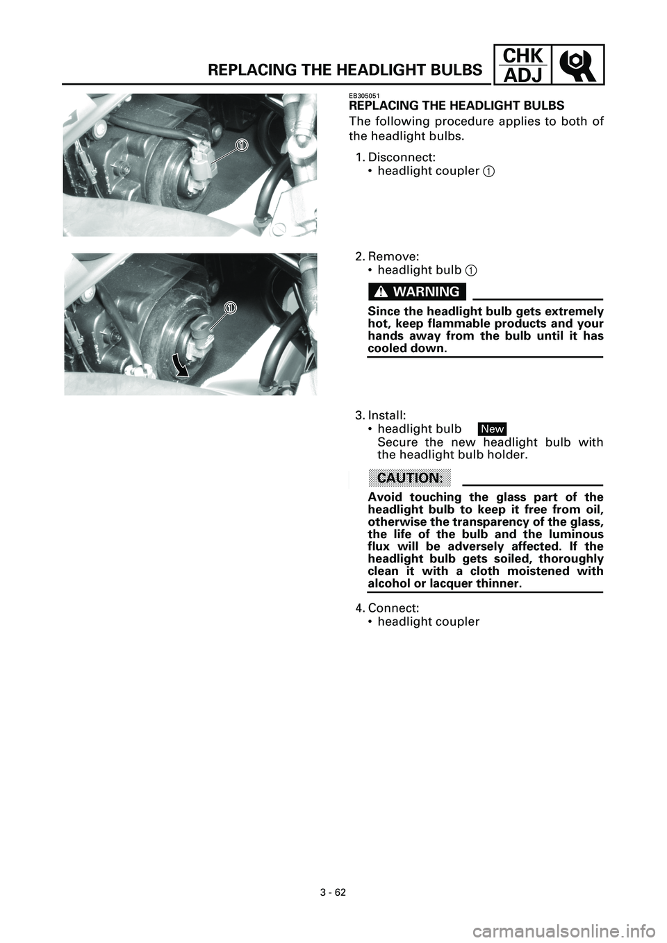
REPLACING THE HEADLIGHT BULBS
EB305051
REPLACING THE HEADLIGHT BULBS
The following procedure applies to both of
the headlight bulbs.
1. Disconnect:
• headlight coupler 1
1�
1�
2. Remove:
• headlight bulb 1
WARNINGWARNING
Since the headlight bulb gets extremely
hot, keep flammable products and your
hands away from the bulb until it has
cooled down.
1�
1�
3. Install:
• headlight bulb
Secure the new headlight bulb with
the headlight bulb holder.
ACHTUNG:CAUTION:
Avoid touching the glass part of the
headlight bulb to keep it free from oil,
otherwise the transparency of the glass,
the life of the bulb and the luminous
flux will be adversely affected. If the
headlight bulb gets soiled, thoroughly
clean it with a cloth moistened with
alcohol or lacquer thinner.
4. Connect:
• headlight coupler
New
Page 132 of 381
3 - 63
CHK
ADJ
ADJUSTING THE HEADLIGHT BEAMS
EB305061
ADJUSTING THE HEADLIGHT BEAMS
The following procedure applies to both of
the headlights.
1. Adjust:
• headlight beam (vertically)
t t t t t t t t t t t t t t t t t t t t t t t t t t t
a. Turn the adjusting screw 1 in direc-
tion a or b.
s s s s s s s s s s s s s s s s s s s s s s s s s s s
Direction aHeadlight beam is raised.
Direction bHeadlight beam is low-
ered.
2. Adjust:
• headlight beam (horizontally)
t t t t t t t t t t t t t t t t t t t t t t t t t t t
a. Turn the adjusting screw 1 in direc-
tion a or b.
Left headlight
Right headlight
s s s s s s s s s s s s s s s s s s s s s s s s s s s
Direction aHeadlight beam moves
to the right.
Direction bHeadlight beam moves
to the left.
Direction aHeadlight beam moves
to the left.
Direction bHeadlight beam moves
to the right.


t t t t t t t")