Page 146 of 381

4 - 14
ENGCAMSHAFTS
2. Check:
• camshaft sprocket
More than 1/4 tooth wear a ® Replace
the camshaft sprockets and the timing
chain as a set.
a1/4 tooth
bCorrect
1Timing chain roller
2Camshaft sprocket
3. Check:
• timing chain guide (exhaust side) 1
• timing chain guide (intake side) 2
• timing chain guide (top side) 3
Damage/wear ® Replace the defective
part(-s).
EB401430
CHECKING THE TIMING CHAIN
TENSIONER
1. Check:
• timing chain tensioner
Cracks/damage/rough movement ®
Replace.
t t t t t t t t t t t t t t t t t t t t t t t t t t t
a. Lightly press the timing chain ten-
sioner rod into the timing chain ten-
sioner housing by hand.
NOTE:
While pressing the timing chain ten-
sioner rod, wind it clockwise with a thin
screwdriver 1 until it stops.
b. Remove the screwdriver and slowly
release the timing chain tensioner
rod.
c. Make sure that the timing chain ten-
sioner rod comes out of the timing
chain tensioner housing smoothly. If
there is rough movement, replace the
timing chain tensioner.
s s s s s s s s s s s s s s s s s s s s s s s s s s s
Page 148 of 381

4 - 16
ENGCAMSHAFTS
4. Install:
• timing chain guide (exhaust side)
5. Install:
• timing chain tensioner
t t t t t t t t t t t t t t t t t t t t t t t t t t t
a. Lightly press the timing chain ten-
sioner rod into the timing chain ten-
sioner housing by hand.
b. While pressing the timing chain ten-
sioner rod, wind it clockwise with a
thin screwdriver 1 until it stops.
c. With the screwdriver still inserted
into the timing chain tensioner, install
the timing chain tensioner and gasket
onto the cylinder block. Then, tighten
the timing chain tensioner bolts to the
specified torque.
WARNINGWARNING
Always use a new gasket.
NOTE:
The “UP” mark on the timing chain ten-
sioner should face up.
d. Remove the screwdriver, make sure
that the timing chain tensioner rod
releases, and tighten the cap bolt to
the specified torque.
s s s s s s s s s s s s s s s s s s s s s s s s s s s
T R..
Timing chain tensioner bolt
10 Nm (1.0 m • kg, 7.2 ft • lb)
T R..
Cap bolt
10 Nm (1.0 m • kg, 7.2 ft • lb)
6. Turn:
• crankshaft
(several turns counterclockwise)
Page 159 of 381

4 - 27
ENGVALVES AND VALVE SPRINGS
t t t t t t t t t t t t t t t t t t t t t t t t t t t
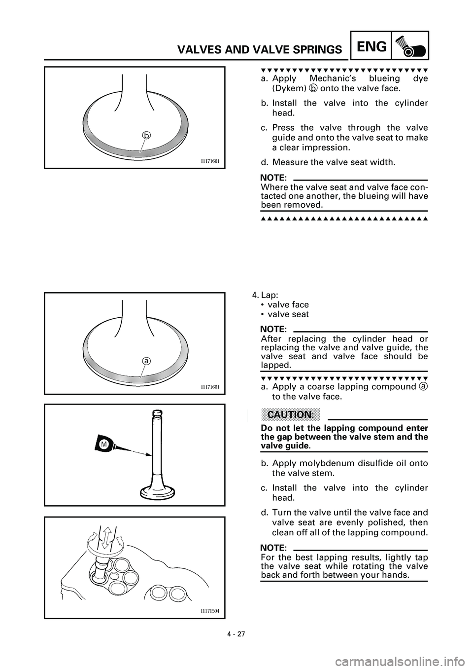
a. Apply Mechanic’s blueing dye
(Dykem) b onto the valve face.
b. Install the valve into the cylinder
head.
c. Press the valve through the valve
guide and onto the valve seat to make
a clear impression.
d. Measure the valve seat width.
NOTE:
Where the valve seat and valve face con-
tacted one another, the blueing will have
been removed.
s s s s s s s s s s s s s s s s s s s s s s s s s s s
4. Lap:
• valve face
• valve seat
NOTE:
After replacing the cylinder head or
replacing the valve and valve guide, the
valve seat and valve face should be
lapped.
t t t t t t t t t t t t t t t t t t t t t t t t t t t
a. Apply a coarse lapping compound a
to the valve face.
ACHTUNG:CAUTION:
Do not let the lapping compound enter
the gap between the valve stem and the
valve guide.
b. Apply molybdenum disulfide oil onto
the valve stem.
c. Install the valve into the cylinder
head.
d. Turn the valve until the valve face and
valve seat are evenly polished, then
clean off all of the lapping compound.
NOTE:
For the best lapping results, lightly tap
the valve seat while rotating the valve
back and forth between your hands.
Page 163 of 381
4 - 31
ENG
VALVES AND VALVE SPRINGS
4. Install:
• valve cotters
1
NOTE:
Install the valve cotters by compressing
the valve spring with the valve spring
compressor
2
and attachment
3
.
5. To secure the valve cotters
1
onto the
valve stem, lightly tap the valve tip with
a soft-face hammer.
ACHTUNG:CAUTION:
Hitting the valve tip with excessive
force could damage the valve.
Valve spring compressor
90890-04019
Attachment
(for the intake valve spring)
9080-04114
(for the exhaust valve spring)
90890-04108
6. Lubricate:
• valve pad
(with the recommended lubricant)
Recommended lubricant
Molybdenum disulfide oil
7. Install:
• valve pad
• valve lifter
NOTE:
• The valve lifter must move smoothly
when rotated with a finger.
• Each valve lifter and valve pad must be
reinstalled in its original position.
Page 246 of 381

6 - 11
EFI
ELECTRONIC FUEL INJECTION
d. Connect the pocket tester (
W
´
1k) to
the throttle position sensor.
e. While slowly opening the throttle,
check that the throttle position sensor
resistance is within the specified
range.
NOTE:
Check mainly that the resistance
changes gradually when turning the
throttle, since the readings (from closed
to wide-open throttle) may differ slightly
from those specified.
Out of specification or the resistance
changes abruptly
®
Go to step 2
below.
s s s s s s s s s s s s s s s s s s s s s s s s s s s
Positive tester probe
®
yellow terminal
3
Negative tester probe
®
black/blue terminal
2
Throttle position sensor resis-
tance
(520 ~ 900
W
) ~ (4.0 ~ 6.0 k
W
)
at 20 ˚C (68 ˚F)
(yellow — black/blue)
2. Check:
• throttle position sensor
(removed from the throttle body)
t t t t t t t t t t t t t t t t t t t t t t t t t t t
a. Disconnect the throttle position sen-
sor coupler from the throttle position
sensor.
b. Remove the throttle position sensor
from the throttle body.
c. Connect the pocket tester (
W
´
1k) to
the throttle position sensor.
Positive tester probe
®
blue terminal
1
Negative tester probe
®
black/blue terminal
2
B/LYL
231
Page 247 of 381

6 - 12
EFI
ELECTRONIC FUEL INJECTION
d. Measure the maximum throttle posi-
tion sensor resistance.
Out of specification
®
Replace the
throttle position sensor.
e. Connect the pocket tester (
W
´
1k) to
the throttle position sensor.
f. While slowly opening the throttle,
check that the throttle position sensor
resistance is within the specified
range.
The resistance does not change or it
changes abruptly
®
Replace the
throttle position sensor.
The slot is worn or broken
®
Replace
the throttle position sensor.
NOTE:
Check mainly that the resistance
changes gradually when turning the
throttle, since the readings (from closed
to wide-open throttle) may differ slightly
from those specified.
s s s s s s s s s s s s s s s s s s s s s s s s s s s
Maximum throttle position
sensor resistance
4.0 ~ 6.0 k
W
at 20 ˚C (68 ˚F)
(blue — black/blue)
Positive tester probe
®
yellow terminal
3
Negative tester probe ®
black/blue terminal 2
Throttle position sensor resis-
tance
0 ~ 5 ± 1.0 kW at 20 ˚C (68 ˚F)
(yellow — black/blue)
Page 248 of 381

6 - 13
EFIELECTRONIC FUEL INJECTION
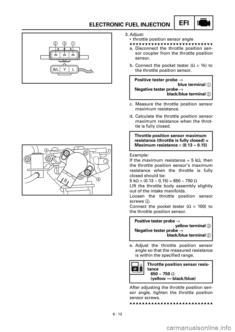
3. Adjust:
• throttle position sensor angle
t t t t t t t t t t t t t t t t t t t t t t t t t t t
a. Disconnect the throttle position sen-
sor coupler from the throttle position
sensor.
b. Connect the pocket tester (W ´ 1k) to
the throttle position sensor.
c. Measure the throttle position sensor
maximum resistance.
d. Calculate the throttle position sensor
maximum resistance when the throt-
tle is fully closed.
Example:
If the maximum resistance = 5 kW, then
the throttle position sensor’s maximum
resistance when the throttle is fully
closed should be:
5 kW ´ (0.13 ~ 0.15) = 650 ~ 750 W
Lift the throttle body assembly slightly
out of the intake manifolds.
Loosen the throttle position sensor
screws 4.
Connect the pocket tester (W ´ 100) to
the throttle position sensor.
e. Adjust the throttle position sensor
angle so that the measured resistance
is within the specified range.
After adjusting the throttle position sen-
sor angle, tighten the throttle position
sensor screws.
s s s s s s s s s s s s s s s s s s s s s s s s s s s
Positive tester probe ®
blue terminal 1
Negative tester probe ®
black/blue terminal 2
Throttle position sensor maximum
resistance (throttle is fully closed) =
Maximum resistance ´ (0.13 ~ 0.15)
Positive tester probe ®
yellow terminal 3
Negative tester probe ®
black/blue terminal 2
Throttle position sensor resis-
tance
650 ~ 750 W
(yellow — black/blue)
B/LYL
231
4�
4�
Page 258 of 381
7 - 8
CHASFRONT WHEEL AND BRAKE DISCS
3. Adjust:
• front wheel static balance
t t t t t t t t t t t t t t t t t t t t t t t t t t t
a. Install a balancing weight 1 onto the
rim exactly opposite the heavy spot
“X”.
NOTE:
Start with the lightest weight.
b. Turn the front wheel 90˚ so that the
heavy spot is positioned as shown.
c. If the heavy spot does not stay in that
position, install a heavier weight.
d. Repeat steps (b) and (c) until the front
wheel is balanced.
s s s s s s s s s s s s s s s s s s s s s s s s s s s
4. Check:
• front wheel static balance
t t t t t t t t t t t t t t t t t t t t t t t t t t t
a. Turn the front wheel and make sure
that it stays at each position shown.
b. If the front wheel does not remain
stationary at all of the positions,
rebalance it.
s s s s s s s s s s s s s s s s s s s s s s s s s s s