Page 958 of 4592
BO0NA±01
H01874
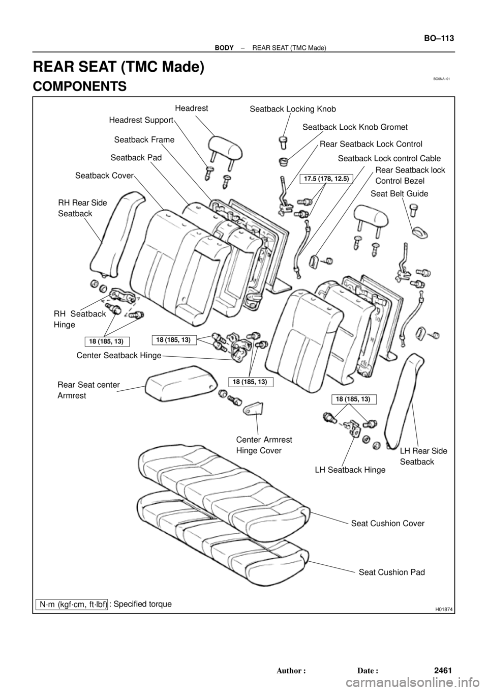
Headrest SupportHeadrest
Seatback Frame
Seatback Pad
Seatback Cover
RH Seatback
Hinge
Center Seatback Hinge
Rear Seat center
Armrest
Center Armrest
Hinge Cover
LH Seatback Hinge
Seat Cushion Cover
Seat Cushion Pad Seatback Locking Knob
Seatback Lock Knob Gromet
Rear Seatback Lock Control
Rear Seatback lock
Control Bezel Seatback Lock control Cable
: Specified torque
N´m (kgf´cm, ft´lbf)
RH Rear Side
Seatback
LH Rear Side
Seatback
18 (185, 13)
18 (185, 13)
18 (185, 13)
17.5 (178, 12.5)
18 (185, 13)
Seat Belt Guide
± BODYREAR SEAT (TMC Made)
BO±113
2461 Author�: Date�:
REAR SEAT (TMC Made)
COMPONENTS
Page 960 of 4592
BO0NC±01
± BODYREAR SEAT (TMC Made)
BO±115
2463 Author�: Date�:
DISASSEMBLY
1. REMOVE SEAT CUSHION COVER
Remove the hog rings and seat cushion cover from the seat cushion pad.
2. REMOVE THESE PARTS:
HINT:
Remove the clips to turn over the seatback cover before performing the following steps.
(a) Headrest
(b) Rear seatback lock control Bezel.
(c) Rear seatback Board
(d) Headrest supports
(e) Seatback locking knob
(f) Seatback lock knob Gromet
(g) Rear seat center armrest
3. REMOVE SEATBACK COVER
(a) Remove the hog rings and seatback frame from the seatback cover with pad.
(b) Remove the hog rings and seatback cover from the seatback pad.
4. REMOVE SEATBACK LOCK
(a) Remove the rear seatback lock control cable.
(b) Remove the 2 bolts and rear seatback lock control.
Torque: 17.5 N´m (178 kgf´cm, 12.5 ft´lbf)
Page 963 of 4592
BO0N5±01
H01875
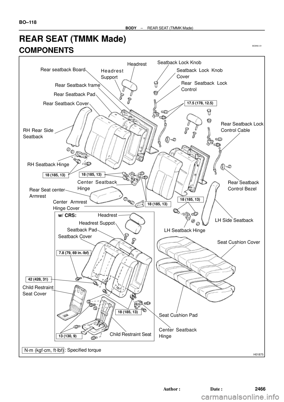
Rear seatback Board
Rear Seatback frame
RH Rear Side
SeatbackRear Seatback CoverRear Seatback PadHeadrest
Support
LH Seatback Hinge Seatback Lock Knob
Seatback Lock Knob
Cover
Rear Seatback Lock
Control Cable
Rear Seatback
Control Bezel
Seat Cushion Cover LH Side Seatback Headrest
Headrest Suppot
Seatback Pad
Seatback Cover
Seat Cushion Pad
Child Restraint Seat Headrest
Rear Seatback Lock
Control
Center Seatback
Hinge
Center Seatback
Hinge
: Specified torque
N´m (kgf´cm, ft´lbf)
RH Seatback Hinge
Rear Seat center
Armrest
18 (185, 13)18 (185, 13)
18 (185, 13)Center Armrest
Hinge Cover18 (185, 13)
18 (185, 13)
7.8 (79, 69 in.´lbf)
42 (428, 31)
13 (130, 9)
17.5 (178, 12.5)
Child Restraint
Seat Coverw/ CRS: BO±118
± BODYREAR SEAT (TMMK Made)
2466 Author�: Date�:
REAR SEAT (TMMK Made)
COMPONENTS
Page 965 of 4592
BO0N7±01
BO±120
± BODYREAR SEAT (TMMK Made)
2468 Author�: Date�:
DISASSEMBLY
1. REMOVE SEAT CUSHION COVER
Remove the hog rings and seat cushion cover from the seat cushion pad.
2. REMOVE THESE PARTS:
HINT:
Remove the clips to turn over the seatback cover before performing the following steps.
(a) Headrest
(b) Rear seatback control Bezel
(c) Headrest supports
(d) Seatback lock knob
(e) Seatback lock knob cover
(f) Rear seat center armrest
3. REMOVE SEATBACK COVER
(a) Remove the hog rings and seatback frame from the seatback cover with pad.
(b) Remove the hog rings and seatback cover from the satback pad.
4. REMOVE SEATBACK LOCK
(a) Remove the rear seatback lock control cable.
(b) Remove the 2 bolts and rear seatback lock control.
Torque: 17.5 N´m (178 kgf´cm, 12.5 ft´lbf)
Page 2013 of 4592

DI05M±02
WIRELESS DOOR LOCK CONTROL System Check Sheet
Customer 's Name
Registration No.
Registration Year
Frame No.
Odometer ReadingInspector 's
Name
km
Miles //
//
// Date Vehicle Brought In
Date Problem First Occurred
Frequency Problem Occurs
Weather Conditions
When Problem Oc-
curred
Date Transmitter Battery Last ReplacedWeather
Outdoor Temperature
PlaceConstant Sometimes ( times per day, month)
Once only
Fine
Cloudy Rainy Snowy
Various/Others
HotWarm Cool
Cold (Approx. °F ( °C))
EverywhereSpecific Locality( )
//
Problem Symptom
Whole wireless door lock control system does not operate.
Only door unlock operation is not possible.
Only door lock operation is not possible.
Only key confinement prevention function is not possible.
Wireless door lock function operates even each door is opened.
Wireless door lock functions incorrectly.
( Although one door is unlocked, when the transmit-
ter switch is pressed, all doors become unlocked.)When Front RH door is unlocked
When Front LH door is unlocked
When Rear RH door is unlocked
When Rear LH door is unlocked
Others
Only PANIC operation is not possible.
± DIAGNOSTICSWIRELESS DOOR LOCK CONTROL SYSTEM
DI±801
1036 Author�: Date�:
CUSTOMER PROBLEM ANALYSIS CHECK
Page 2040 of 4592

DI1KU±02
DI±828
± DIAGNOSTICSTHEFT DETERRENT SYSTEM
1063 Author�: Date�:
PRE±CHECK
1. Active arming mode:
SETTING THE THEFT DETERRENT MODE
The system will be automatically set to the theft deterrent mode
about 30 seconds after the setting processes listed below are
performed.
Setting Processes: (do processes (1)�(4) in the order)
(1) Remove the ignition key from the key cylinder.
(2) Close all entry points (door, hood and luggage
compartment door).
(3) Use any one of the following methods to lock all the
doors depending on a given condition.
�Use the key to lock the driver or passenger
side door. (as a result, all the doors(including
the engine hood and luggage compartment
door) will be closed and locked), or
�Use the remote control to lock any door (as a
result, all the doors(including the engine
hood and luggage compartment door) will be
closed and locked), or
�If the front right or left door is unlocked when
both the rear doors are already locked, lock
and close the remaining unlocked door by
hand (as a result, all the doors(including the
engine hood and luggage compartment door)
will be closed and locked).
�Close all doors and lock with the engine hood
or luggage compartment door opened, and
close the engine hood or all the doors(includ-
ing the engine hood and luggage compart-
ment door).
(4) About 30 seconds after the above process (3), the
theft deterrent mode will automatically start.
HINT:
The closing/locking of all the entry points (doors, hood and lug-
gage) must remain unchanged for about 30 seconds, the sys-
tem will start the theft deterrent mode.
2. Passive arming mode:
SETTING THE THEFT DETERRENT MODE
The system will be automatically set to the theft deterrent mode
about 30 seconds after the setting processes listed below are
performed.
Setting Processes:
(1) Remove the ignition key from the key cylinder.
(2) Open and close any entry points (door, hood and
luggage compartment door).
Now, all the entry points are closed.
Page 2617 of 4592
A02188
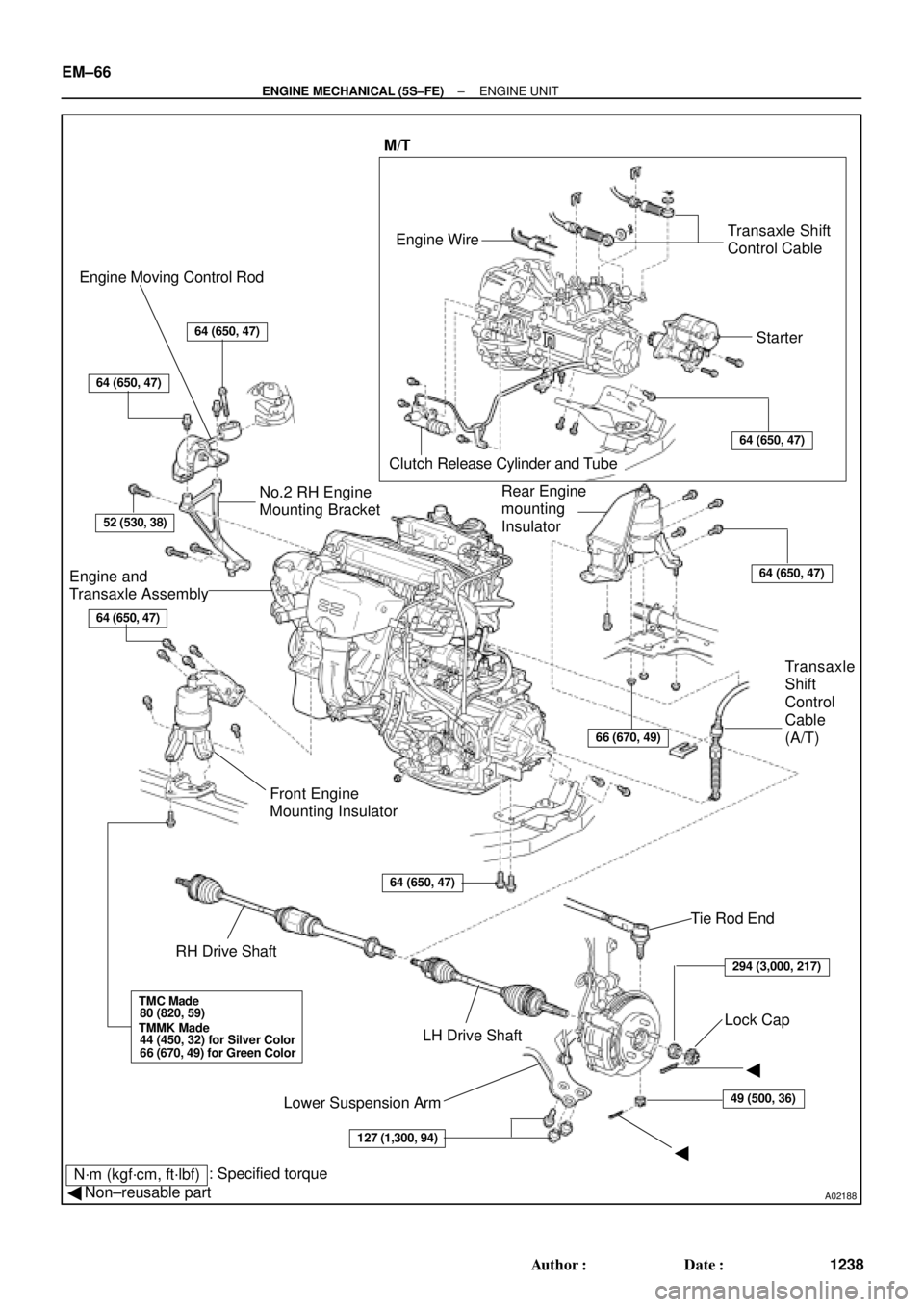
Engine Moving Control Rod
Engine and
Transaxle Assembly
Front Engine
Mounting Insulator
RH Drive Shaft
Lower Suspension ArmLH Drive Shaft No.2 RH Engine
Mounting BracketRear Engine
mounting
Insulator
Transaxle
Shift
Control
Cable
(A/T)
Tie Rod End
Lock CapTransaxle Shift
Control Cable
Clutch Release Cylinder and Tube Engine Wire
��Starter M/T
N´m (kgf´cm, ft´lbf)
64 (650, 47)
64 (650, 47)
127 (1,300, 94)
52 (530, 38)
64 (650, 47)
66 (670, 49)
49 (500, 36)
64 (650, 47)
64 (650, 47)
64 (650, 47)
294 (3,000, 217)
TMC Made
80 (820, 59)
TMMK Made
44 (450, 32) for Silver Color
66 (670, 49) for Green Color
: Specified torque
� Non±reusable part
EM±66
± ENGINE MECHANICAL (5S±FE)ENGINE UNIT
1238 Author�: Date�:
Page 2735 of 4592
A06646
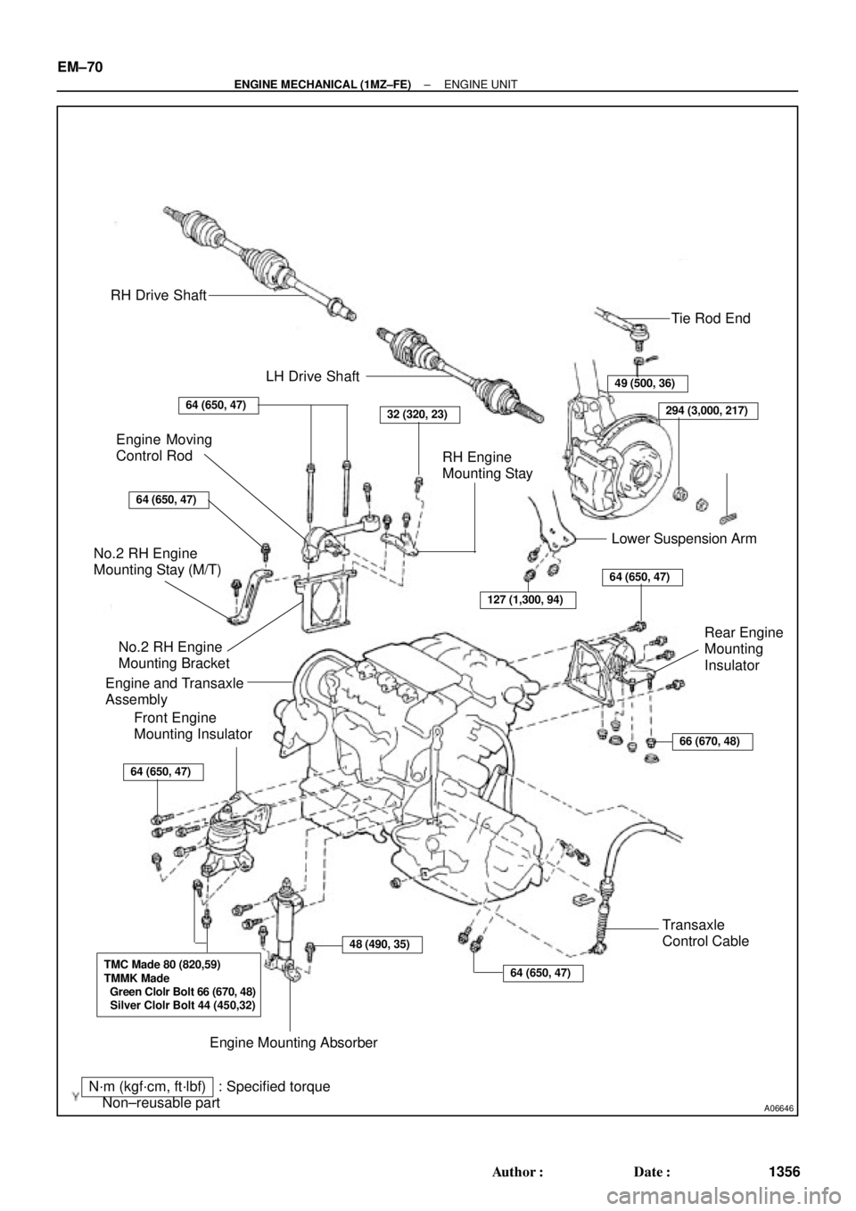
RH Drive Shaft
LH Drive Shaft
Tie Rod End
49 (500, 36)
294 (3,000, 217)64 (650, 47)32 (320, 23)
RH Engine
Mounting Stay
Lower Suspension Arm Engine Moving
Control Rod
64 (650, 47)
127 (1,300, 94)
No.2 RH Engine
Mounting Stay (M/T)
No.2 RH Engine
Mounting Bracket
Engine and Transaxle
Assembly
64 (650, 47)
66 (670, 48)
64 (650, 47)
Front Engine
Mounting Insulator
48 (490, 35)
64 (650, 47)
Transaxle
Control Cable
Engine Mounting Absorber
TMC Made 80 (820,59)
TMMK Made
Green Clolr Bolt 66 (670, 48)
Silver Clolr Bolt 44 (450,32)
N´m (kgf´cm, ft´lbf) : Specified torque
� Non±reusable part�
Rear Engine
Mounting
Insulator
EM±70
± ENGINE MECHANICAL (1MZ±FE)ENGINE UNIT
1356 Author�: Date�: