Page 4038 of 4592
G
Position of Parts in Engine Compartment
I 1 Idle Air Control Valve
I 2 Ignition Coil and Igniter No.1
I 3 Ignition Coil and Igniter No.2
I 4 Injector No.1
I 5 Injector No.2
I 6 Injector No.3
I 7 Injector No.4
I 8 Intake Air Temp. Sensor
M 1 Manifold Absolute Pressure Sensor
N 1 Noise Filter (Ignition)
O 1 Oil Pressure SW
P 1 Park/Neutral Position SW,A/T Indicator Light SW and
Back±Up Light SW
P 2 Power Steering Oil Pressure SWR 1 Radiator Fan Motor
S 1 Starter
S 2 Starter
T 1 Throttle Position Sensor
V 1 Vehicle Speed Sensor (Combination Meter)
V 2 VSV (EGR)
W 1 Washer Level Warning SW
W 2 Washer Motor
W 3 Water Temp. Sender
W 4 Water Temp. SW No.1
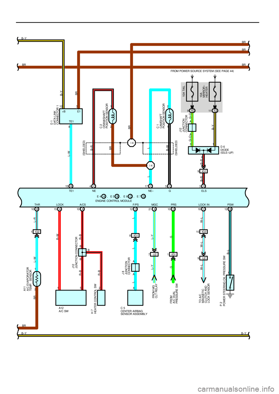
Page 4064 of 4592
FROM POWER SOURCE SYSTEM (
SEE PAGE 44)
1C 91J11
1 2
2 1
IJ2 7
IJ2 9IG3 10 IG2 1
1 I 4 I 4
A 10 A 15A 21 D10 C18 B 10B 12 B 15 C4C17 C5D3
2 1B 8
2 A
B 12 3
A
1 3
2 5 1
BR
B±YBR B±Y
BR
BR
BR
B±Y TE1
B± LL±R L±W BR
W± L W±L W± LG L±Y
G L±Y R±BR±B R±W
R±BL±W
B± R
BR
L
B±W
G± O G± O
B±YB±Y
BR
E1 +B
10A TAIL
10A
MIRROR±
HEATER (
SHIELDED)
(
SHIELDED) L
B±R
DIODE
(
IDLE±UP)
DATA LINK
CONNECTOR 1
CRANKSHAFT
POSITION SENSOR
CAMSHAFT
POSITION SENSOR
JUNCTION
CONNECTORD 1
C 2
C 1
J12
D 6
JUNCTION CONNECTOR
A/C SWHEATER CONTROL SW
POWER STEERING OIL PRESSURE SWFROM MG
CLT RELAY
FROM
A/C DUAL
PRESSURE SW
TO A/C
MAGNETIC
CLUTCH AND
LOCK SENSORJ12
P 2 H 7
A12
BR
ENGINE CONTROL MODULEB E 4 E 5ACE 6 , , D, E 7
IG1 8D 12
LL JUNCTION
CONNECTOR J 8
C 5
CENTER AIRBAG
SENSOR ASSEMBLYIG1 9
B± R
A A
4
L
TE1 NE NE± G EL S
LOCK A/CS F/PS MGC PRS LOCK IN THRPSW
A/C EVAPORATOR
TEMP. SENSOR A11
B
IG1 1
Page 4124 of 4592

SRS
NOTICE: When inspecting or repairing the SRS, perform the operation in accordance with the following precautionary
instructions and the procedure and precautions in the Repair Manual for the applicable model year.
�Malfunction symptoms of the SRS are difficult to confirm, so the DTCs become the most important source of information
when troubleshooting. When troubleshooting the SRS, always inspect the DTCs before disconnecting the battery.
�Work must be started after 90 seconds from when the ignition switch is turned to the ºLOCKº position and the
negative (±) terminal cable is disconnected from the battery.
(The SRS is equipped with a back±up power source so that if work is started within 90 seconds from
disconnecting the negative (±) terminal cable of the battery, the SRS may be deployed.)
�When the negative (±) terminal cable is disconnected from the battery, the memory of the clock and audio system will be
canceled. So before starting work, make a record of the contents memorized in the audio memory system. When work is
finished, reset the audio systems as they were before and adjust the clock. To avoid erasing the memory in each
memory system, never use a back±up power supply from outside the vehicle.
�Before repairs, remove the airbag sensor if shocks are likely to be applied to the sensor during repairs.
�Do not expose the steering wheel pad, front passenger airbag assembly, seat belt pretensioner, center airbag sensor
assembly or front airbag sensor assembly directly to hot air or flames.
�Even in cases of a minor collision where the SRS does not deploy, the steering wheel pad, front passenger airbag
assembly, seat belt pretensioner, center airbag sensor assembly and front airbag sensor assembly should be inspected.
�Never use SRS parts from another vehicle. When replacing parts, replace them with new parts.
�Never disassemble and repair the steering wheel pad, front passenger airbag assembly, seat belt pretensioner, center
airbag sensor assembly or front airbag sensor assembly in order to reuse it.
�If the steering wheel pad, front passenger airbag assembly, seat belt pretensioner, center airbag sensor assembly or
front airbag sensor assembly has been dropped, or if there are cracks, dents or other defects in the case, bracket or
connector, replace them with new ones.
�Use a volt/ohmmeter with high impedance (10 kW/V minimum) for troubleshooting the system's electrical circuits.
�Information labels are attached to the periphery of the SRS components. Follow the instructions on the notices.
�After work on the SRS is completed, perform the SRS warning light check.
�If the vehicle is equipped with a mobile communication system, refer to the precaution in the IN section of the Repair
Manual.
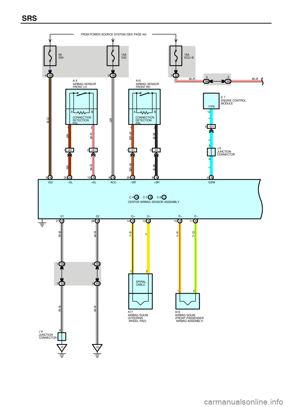
Page 4125 of 4592
SRS
5A
IGN
1N 415A
CIG FROM POWER SOURCE SYSTEM (
SEE PAGE 44)
1N 210A
ECU±B
2J 7
1G2
1W3
B 5B6
1N 1
1J 71N 3
1V 3
IF ID AB 27 B28
12
SPIRAL
CABLE
2 1 B 14 B13 B10 B11
B±O
GR
Y±GY±RY Y±B W±B W±B W±B
W±B
W±R W±R
AIRBAG SQUIB
(
STEERING
WHEEL PAD) A17
AIRBAG SQUIB
(
FRONT PASSENGER
AIRBAG ASSEMBLY) A16
JUNCTION
CONNECTOR J 9C 4
CENTER AIRBAG SENSOR ASSEMBLYB A, C 5
C , C 6 B 26 B15 B20 B9 IA1 1IA12 1 II1 II12
BR BR
W± R
BR±W
B±W W±R
BR±W
B±W
AIRBAG SENSOR
FRONT L H A 9
AIRBAG SENSOR
FRONT RH A10
CONNECTION
DETECTION
PIN
2 1 CONNECTION
DETECTION
PIN
2 1AB AB
IG2 ±SL +SL ACC ±SR +SR
E1 E2 D+ D± P+ P±IG1 8
B 4A AENGINE CONTROL
MODULE E 7
12
L L L
JUNCTION
CONNECTOR J 8
GSWF/PS
Page 4182 of 4592

L
CodePart Name Part NumberCodePart Name Part Number
G 2Generator90980±11349
G 3Glove Box Light and SW90980±11098
H 1Headlight LH90980±11314H 2Headlight RH90980±11314
H 3Horn (High)90980±10619H 4Horn (Low)90980±10619
H 5Hazard SW90980±10801
H 6Heated Oxygen Sensor90980±11028
H 7Heater Control SW90980±10799
H 8High Mounted Stop Light90980±11148
I 1Idle Air Control Valve90980±11145
I 2Ignition Coil and Igniter No.190980±11150I 3Ignition Coil and Igniter No.290980±11 150
I 4Injector No.1
I 5Injector No.290980±11153I 6Injector No.390980±11 153
I 7Injector No.4
I 8Intake Air Temp. Sensor90980±11163
I 9Ignition Key Cylinder Light90980±10906
I10Ignition SW90980±11615
I11Integration Relay90980±11107
I12Integration Relay90980±11542
I13Interior Light90980±10121
J 1Junction Connector90980±10803
J 2Junction Connector90980±11542
J 3Junction Connector90980±10803
J 4Junction Connector90980±11542
J 5Junction Connector90980±11502
J 6Junction Connector90980±11661J 7Junction Connector90980±11661
J 8Junction Connector90980±11398
J 9Junction Connector90980±10976
J10Junction Connector90980±11661J11Junction Connector90980±11661
J12Junction Connector90980±10803
J13Junction Connector90980±11661J14Junction Connector90980±11661
J15Junction Connector90980±10803
J16Junction Connector90980±11661J17Junction Connector90980±11661
J18Junction Connector90980±11542J19Junction Connector90980±11542
J20Junction Connector90980±11539
J21Junction Connector90980±11529
J22Junction Connector90980±11502
J23Junction Connector
J24Junction Connector90980±11661J25Junction Connector90980±11661
J26Junction Connector
J27Junction Connector90980±11542
J28Junction Connector90980±11661J29Junction Connector90980±11661
J30Junction Connector90980±10803
J31Junction Connector90980±11661J32Junction Connector90980±11661
J33Junction Connector90980±10803
J34Junction Connector90980±10976
J35Junction Connector90980±10803
K 1Key Interlock Solenoid90980±10825
L 1License Plate Light LH90980±11148L 2License Plate Light RH90980±11148
L 3Light Failure Sensor90980±10803
L 4Luggage Compartment Light90980±11148
L 5Luggage Compartment Light SW90980±11097
M 1Manifold Absolute Pressure Sensor90980±10845
N 1Noise Filter (Ignition)90980±10843
N 2Noise Filter (Rear Window Defogger)90980±11259
O 1Oil Pressure SW90980±11363
O 2O/D Main SW and A/T Shift Lever
Illumination90980±10795
P 1Park/Neutral Position SW,A/T Indicator Light
SW and Back±Up Light SW90980±11332
P 2Power Steering Oil Pressure SW90980±11428
P 3Parking Brake SW90980±10871
P 4Power Outlet90980±10760
P 5Power Window Control SW Front RH90980±10789
P 6Power Window Control SW Rear LH90980±10631P 7Power Window Control SW Rear RH90980±10631
P 8Power Window Master SW and Door Lock
Control SW LH90980±10807
P 9Power Window Motor Front LH
P10Power Window Motor Front RH90980±10860P11Power Window Motor Rear LH90980±10860
P12Power Window Motor Rear RH
P13Pretensioner LH90980±11862P14Pretensioner RH90980±11862
R 1Radiator Fan Motor90980±10928
R 2Radio and Player90980±10996
R 3Radio and Player90980±10997
R 4Rear Window Defogger SW90980±11280
R 5Remote Control Mirror SW90980±11450
Page 4216 of 4592

1
234
14 CAMRY CNG
28
,
B 10AB
2
12A
Y± BY
P13
PRETENSIONER LHA 1 2ACC
IG1
IG2
ST2 AM13
I10
IGNITION SW6 7AM2
1ACENTER AIRBAG SENSOR ASSEMBLY
,
1B 1
1F 1C1K 2
2A 1
10A ECU±B
2J 7
42L
30A
AM2
B±G
1B 51K 5
SHORT
PI N
100A
ALT1K 3
A17
AIRBAG SQUI B
(
Steering
Wheel Pad)
IF1N 4
1N 11W 3
1G 2
1J 7
Co wl si d e
panel LH ID A1N 3
1V 3 12
SPIRAL
CABLE
12B
B± RB
W± R
W±R
W
W
B±RL±RW± R
B±O LG
FL MAIN
3. 0W
BATTERY
W± B
W± RW±BW± B
Y± BY Y±R Y± G W± B
1 213 12
J 9
JUNCTION
CONNECTORA1 6
AI RBAG SQUIB
(
Fr ont Passenger
Ai r bag As se mb ly)W±R
W± RC11
SRS WARNING LIGHT
[COMB. METER]
B
FUSIBLE LINK BLOCKF F1 4 C F1 1 A F 9
11
Ins trument panel
brace LH 1 2
, C 5 C 4 C, C 6 5B1K 6
1N 2
GR6BA
P±B
LG LG To Data Link
Connec tor 1, 2
< 15±3>
3B 19BAB± Y J 2
JUNCTION
CONNE CT OR
5
12CY± BY
P14
PRETENSI ONER RHC 6 14 B 13 B 27 B
Power Source
SRS
To Data Link Connect or 3
< 2±7>12 B
W
±SL2IE27IG3
W± R
B 26
B± W
BR±W
15 B
B± W
20 B
BR
9B 2 IA1 1 II1 II122 1 2 1
BR±W
W± R
BR
A 9
AI RBAG SENSOR
FRONT L HA10
AI RBAG SENSOR
FRONT RH
2F+S R
B±R B±R
±SR +S LA
LA TC
PL+ PL± PR+ PR± E2 SIL E1 D+ D± P+ P±IG2 ACCLG CONNE CT I ON
DE TE CT I ON
PI NCONNECTION
DETECTION
PIN
15A
CI G 5A
IGN
1IA1
To Engine Cont rol
Module< 2±7>4BLGSW AABB
40A
AM1
To Data Link
Connector 1
< 15±3>
Page 4254 of 4592
G
Position of Parts in Engine Compartment
[1MZ±FE]
I 1 Idle Air Control Valve
I 2 Igniter
I 5 Ignition Coil No.1
I 6 Ignition Coil No.2
I 7 Ignition Coil No.3
I 8 Injector No.1
I 9 Injector No.2
I 10 Injector No.3
I 11 Injector No.4
I 12 Injector No.5
I 13 Injector No.6
K 1 Knock Sensor 1
K 2 Knock Sensor 2
M 2 Mass Air Flow Meter
N 1 Noise Filter (Ignition)
O 1 Oil Pressure SW
P 1 Park/Neutral Position SW,A/T Indicator Light SW and
Back±Up Light SW
P 2 Power Steering Oil Pressure SWR 1 Radiator Fan Motor
S 1 Starter
S 2 Starter
T 1 Theft Deterrent Horn
T 2 Throttle Position Sensor
V 2 Vehicle Speed Sensor (Combination Meter)
V 3 Vehicle Speed Sensor
(Electronically Controlled Transmission)
V 4 VSV (EGR)
V 5 VSV (EVAP)
V 6 VSV (Intake Air Control)
W 1 Washer Level Warning SW
W 2 Washer Motor
W 3 Water Temp. Sender
W 4 Water Temp. SW No.1
W 5 Water Temp. SW No.2
Page 4256 of 4592
G
Position of Parts in Engine Compartment
[5S±FE]
I 1 Idle Air Control Valve
I 3 Ignition Coil and Igniter No.1
I 4 Ignition Coil and Igniter No.2
I 8 Injector No.1
I 9 Injector No.2
I 10 Injector No.3
I 11 Injector No.4
I 14 Intake Air Temp. Sensor
K 1 Knock Sensor 1
M 1 Manifold Absolute Pressure Sensor
N 1 Noise Filter (Ignition)
O 1 Oil Pressure SW
P 1 Park/Neutral Position SW,A/T Indicator Light SW and
Back±Up Light SW
P 2 Power Steering Oil Pressure SWR 1 Radiator Fan Motor
S 1 Starter
S 2 Starter
T 1 Theft Deterrent Horn
T 2 Throttle Position Sensor
V 2 Vehicle Speed Sensor (Combination Meter)
V 4 VSV (EGR)
V 5 VSV (EVAP)
W 1 Washer Level Warning SW
W 2 Washer Motor
W 3 Water Temp. Sender
W 4 Water Temp. SW No.1

![TOYOTA CAMRY 1999 Service Repair Manual G
Position of Parts in Engine Compartment
[1MZ±FE]
I 1 Idle Air Control Valve
I 2 Igniter
I 5 Ignition Coil No.1
I 6 Ignition Coil No.2
I 7 Ignition Coil No.3
I 8 Injector No.1
I 9 Injector No.2
I 10](/manual-img/14/57448/w960_57448-4253.png "TOYOTA CAMRY 1999 Service Repair Manual G
Position of Parts in Engine Compartment
[1MZ±FE]
I 1 Idle Air Control Valve
I 2 Igniter
I 5 Ignition Coil No.1
I 6 Ignition Coil No.2
I 7 Ignition Coil No.3
I 8 Injector No.1
I 9 Injector No.2
I 10")
![TOYOTA CAMRY 1999 Service Repair Manual G
Position of Parts in Engine Compartment
[5S±FE]
I 1 Idle Air Control Valve
I 3 Ignition Coil and Igniter No.1
I 4 Ignition Coil and Igniter No.2
I 8 Injector No.1
I 9 Injector No.2
I 10 Injector No](/manual-img/14/57448/w960_57448-4255.png "TOYOTA CAMRY 1999 Service Repair Manual G
Position of Parts in Engine Compartment
[5S±FE]
I 1 Idle Air Control Valve
I 3 Ignition Coil and Igniter No.1
I 4 Ignition Coil and Igniter No.2
I 8 Injector No.1
I 9 Injector No.2
I 10 Injector No")